
Fibre Channel (FC) can be used to connect additional FC-capable storage devices to the Oracle Private Cloud Appliance (PCA) using the FC ports available on the Fabric Interconnects. The Oracle PCA automatically creates virtual Host Bus Adaptors (vHBAs) on each server in the Oracle PCA rack. The World Wide Port Names (WWPNs) defined for these vHBAs can be used to define Initiator Groups on your storage appliance to facilitate access to the LUNs that you wish to make available to your compute and management nodes.
Oracle PCA introduces the concept of "storage clouds" that group together the FC ports used to connect the Fabric Interconnects to your own FC switch or switches. Two FC ports on each of the Fabric Interconnects are assigned to a cloud. A vHBA is created on each server for each storage cloud. A total of four storage clouds are defined when the Oracle PCA is provisioned, resulting in four vHBAs on each of the compute and management nodes.
Storage clouds allow you to cable and configure your external storage in such a way as to improve overall throughput or to build a fully HA enabled infrastructure. The storage clouds are created and configured automatically, so that all you need to do is choose the type of HA configuration that you wish to use and then cable accordingly. The design of the storage cloud configuration reduces complexity in configuration and allows the greatest possible flexibility in terms of your HA requirements.
At bare minimum, a single cloud can be used to access storage on each of your compute nodes or on your management nodes. However a simple HA configuration is recommended. To achieve this, you should use at least two clouds cross-cabled from each of the Fabric Interconnects. For a fully HA-enabled environment, you can use all four clouds cross-cabled between the Fabric Interconnects and two of your own FC switches.
If you do not require HA, you can use multiple clouds to increase overall throughput. In this configuration, you can cable three clouds into separate switches and connect them to the same storage. If one cloud should fail, you are able to bring up the fourth cloud to take over its function and to maintain the same level of throughput.
Each of these configurations is achieved entirely through the different ways in which your FC switch or switches are patched into the Fabric Interconnects. These approaches are described in more detail in Section 7.2.2, “Connecting Fibre Channel Hardware”.
Since storage clouds map directly to the vHBAs on each server, it is possible to configure zones on your FC switch or switches to securely separate traffic for each storage cloud. This gives you the opportunity to use separate clouds for different purposes using secured channels to facilitate communication between servers and the LUNs on your storage. This is described in Section 7.2.3, “Zone Configuration”.
To use Fibre Channel with the Oracle PCA , you must supply your own NPIV-capable FC switch or switches. It is not possible to simply patch your FC-capable storage directly into the FC ports on the Fabric Interconnects. This is because the Fabric Interconnects use NPIV to map the port nodes to the World Wide Node Names (WWNNs) of the vHBAs that are created on each server. Software required to translate WWPNs to WWNNs does not exist on the storage heads of most FC storage devices, so directly attaching the storage device would prevent registration of the WWPNs for the vHBAs available on each server.
Each server in the Oracle PCA is connected to the Fabric Interconnects via an InfiniBand (IB) connection. The Fabric Interconnects are capable of translating connections on their Fibre Channel ports to reroute them over these IB connections. To facilitate this, vHBAs must be defined on each server to map to a storage cloud defined on the Fabric Interconnects. The storage cloud that these vHBAs map to, determine which FC ports they relate to on the Fabric Interconnects.
During the initial configuration of the management nodes, each of the storage clouds is configured automatically on the Fabric Interconnects and vHBAs for each cloud are created on each of the management nodes. WWNNs and WWPNs are generated for the vHBAs on the management nodes. When you cable for a storage cloud and connect your storage appliance, you can add these WWPNs to a storage initiator group and export the LUNs that you wish to make available to your management nodes. These disks can then be mounted on the management nodes as needed. Management nodes are configured with vHBAs to allow them to connect to the different storage clouds so that it is possible to use externally connected storage to store backup and log data, if required.
It is important to distinguish between WWNNs and WWPNs. A WWNN is used to identify a device or node such as an HBA, while a WWPN is used to identify a port that is accessible via that same device. Since some devices can have multiple ports, a device may have a single WWNN and multiple WWPNs.
In the case of the vHBAs that are generated on each compute node, there is a single WWNN and a single WWPN for each vHBA. While these may look almost identical, the fourth hexadecimal octet that makes up the WWN differs. This is illustrated as follows:
WWPN | WWNN |
|---|---|
50:01:39:70:00:4F:91:00 | 50:01:39:71:00:4F:91:00 |
When configuring storage initiators and initiator groups, you should ensure that you are configuring these for the WWPN for each vHBA. If you use the WWNN for any vHBA within an initiator group, that initiator group may not function as expected.
Compute nodes are configured similarly, although the process takes place during compute node provisioning, so that compute nodes are configured as they are provisioned. This means that if you add a compute node to the rack, it is automatically configured so that it is ready to access any externally attached storage. Creation and configuration of vHBAs has also been built into the upgrade process, so that external FC storage can be used with existing environments. Once you have cabled for your storage and have configured the initiator groups on your storage, you can view the LUNs that you make available to your compute nodes directly in Oracle VM Manager.
These processes are entirely automated and do not require any intervention.
Cabling requirements to attach external FC-capable storage to the Oracle PCA are very specific due to the grouping of FC ports for storage clouds on the Fabric Interconnects. You must ensure that when cabling for a storage cloud, both ports defined for the storage cloud are cabled into your FC switch. Ideally, you should cable all four FC ports on each of the Fabric Interconnects within the rack for a total of eight cables, at the same time. These should either connect to a single Fibre Channel switch outside of the rack, or should be cross-connected to two Fibre Channel switches outside of the rack to improve redundancy. The following table describes how ports are grouped to create each cloud:
Table 7.2 Fibre Channel Port and Cloud Mappings
Top Oracle Fabric Interconnect F1-15 (RU 22-25): | Bottom Oracle Fabric Interconnect F1-15 (RU 15-18): | |||
|---|---|---|---|---|
Cloud Name | I/O Module 3 | I/O Module 12 | I/O Module 3 | I/O Module 12 |
A | Port 1 | Port 1 | ||
B | Port 2 | Port 2 | ||
C | Port 1 | Port 1 | ||
D | Port 2 | Port 2 | ||
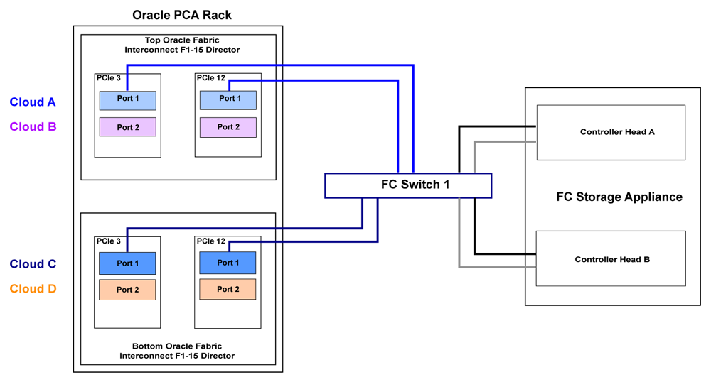
For a bare minimum configuration, you can use two cables to connect your FC switch to cloud A. This would require that you connect cables to the top Fabric Interconnect in the rack, using I/O Module 3 Port 1 and I/O Module 12 Port 1. Connect each controller head on your FC storage appliance to your FC switch. Typically you would use two cables for each controller head.
For a basic HA configuration, you should cable for cloud A and cloud C. This allows you to use both of the Fabric Interconnects in the rack to improve redundancy. This is the recommended default minimum configuration. It is important that cloud A and cloud C are cabled to the same FC switch.
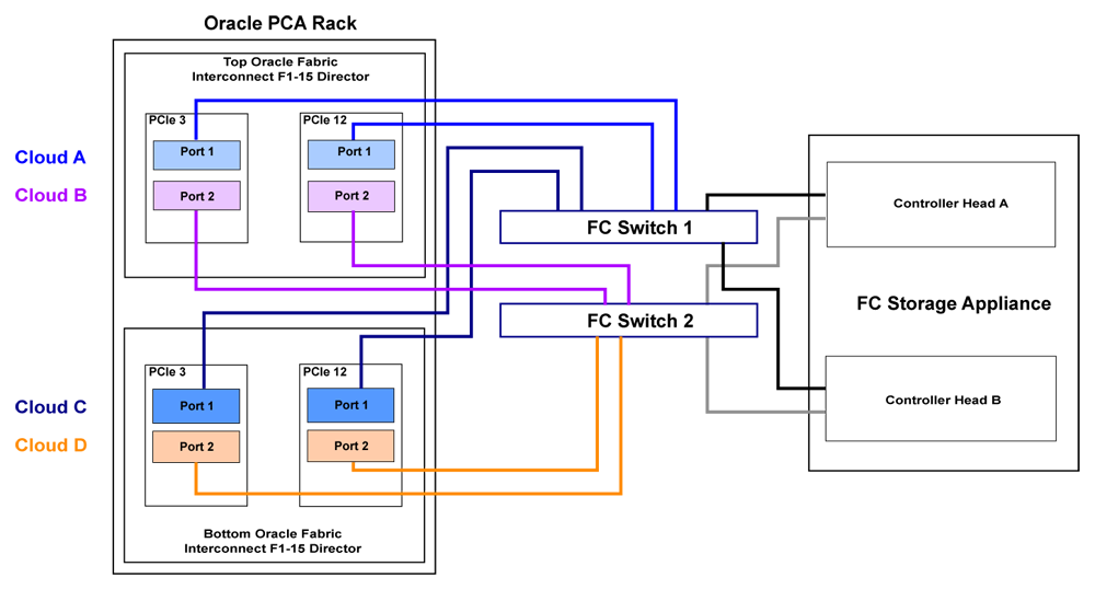
To maximize an HA configuration, by using an additional FC switch, you can cable cloud B and cloud D into the second FC switch. In this situation you should cross-cable the controller heads on your FC storage appliance, so that each controller head is connected to each of your FC switches.
Other cabling possibilities exist, such as the aforementioned configuration where clouds are each connected to independent FC switches to maximize throughput or to achieve physical traffic separation. Usually, in this configuration, one cloud is left disconnected in standby so that in the event that one of the other clouds fails for some reason, it is possible to connect the standby cloud to take over the function of the failed cloud. In this situation, you would need to configure so that the WWPNs for the standby cloud are substituted for the failed cloud in the initiator groups on your storage appliance.
The most important points to remember when cabling are as follows:
Clouds are comprised of two equivalent ports on alternate I/O Modules on the same Fabric Interconnect. For instance, cloud A on the top Fabric Interconnect in the rack is comprised of Port 1 on I/O Module 3 and Port 1 on I/O Module 12; while cloud D on the bottom Fabric Interconnect in the rack is comprised of Port 2 on I/O Module 3 and Port 2 on I/O Module 12.
Although not required, you should cable both ports that belong to a cloud to provide redundancy and to allow better throughput.
Unless you have defined zones that span more than one FC switch, the ports that belong to a cloud must be cabled to connect to the same FC switch.
For HA configurations, clouds on alternate Fabric Interconnects should be connected to the same FC switch. For instance, cloud A and cloud C should be connected to the same FC switch; while cloud B and cloud D can be connected to an alternate switch.
You can connect FC cabling at any time, and no system shutdown is required, allowing you to hot-add storage or improve redundancy as required.
The Oracle PCA has been tested in conjunction with FC zoning configured on the external FC switches. Fibre Channel Zoning is used to enhance security by providing an extra layer of traffic separation on the storage network. Even if you are using storage initiator groups to perform LUN masking, it is generally considered good practice to also configure FC zones to limit the exposure of LUNs and unrestricted use of this network medium. Zone configuration is very useful in the situation where the FC switch or switches are shared with other devices apart from the Oracle PCA. Furthermore zones can allow you to group ports across switches so that you can cross-cable for each cloud across two switches for greater redundancy.
Only D,P (Domain, Port) zones can be configured for connections to the Oracle PCA. It is not possible to configure zones based on the port WWNs for the vHBAs configured on each server in the Oracle PCA rack. This is because the Fabric Interconnects use NPIV to allow the vHBAs to share the same physical ports, the result is that the port WWNs are hidden from the switch or switches. D,P zones require much less maintenance and are more easily scaled within an Oracle PCA context.
A single D,P zone can be configured to protect all traffic moving between the Oracle PCA and the storage appliance. Alternatively, you can take advantage of the fact that the four storage clouds defined on the Fabric Interconnects correlate to matching ports on each I/O Module. This means that it is possible to configure a zone for each separate cloud, if you choose to use clouds independently of each other. In general, a single zone should be sufficient, but you are capable of configuring your zones as you require, as long as they are based on D,P zoning.
Although zoning is recommended, this step is optional and there is no requirement to configure FC zones on your switch or switches. If you decide to implement FC zoning, please refer to the documentation of your switch vendor for more information on the configuration steps that you must perform.
Some initial configuration steps may be required on your appliance before you are able to access storage directly within Oracle VM Manager. Typically these steps involve configuring some form of 'LUN masking' achieved by mapping LUNs to particular initiator groups that ultimately define the servers and clouds that have access to each LUN. These steps are outlined as follows:
Create the initiators that you intend to use to identify the different servers in each cloud within your storage appliance. This is achieved by registering the World Wide Port Names (WWPNs) that were created for the vHBAs on each server in the Oracle PCA rack with your appliance and assigning them aliases so that they can be easily identified as belonging to a particular server and cloud. Most appliances should be able to see the WWPNs presented by the Fabric Interconnects and you can use the Oracle PCA command line interface to identify matching WWPNs and match them with the recommended aliases that you should use when creating each initiator. This is achieved by running the pca-admin list wwpn-info command:
PCA> list wwpn-info

WWPN                      vHBA     Cloud_Name    Server       Type  Alias
-------------             ----     ------------  ---------    ----  --------------
50:01:39:70:00:4F:91:00   vhba01   Cloud_A       ovcamn05r1   MN    ovcamn05r1-Cloud_A
50:01:39:70:00:4F:91:02   vhba01   Cloud_A       ovcamn06r1   MN    ovcamn06r1-Cloud_A
50:01:39:70:00:4F:91:04   vhba01   Cloud_A       ovcacn07r1   CN    ovcacn07r1-Cloud_A
50:01:39:70:00:4F:91:06   vhba01   Cloud_A       ovcacn08r1   CN    ovcacn08r1-Cloud_A
50:01:39:70:00:4F:91:01   vhba02   Cloud_B       ovcamn05r1   MN    ovcamn05r1-Cloud_B
50:01:39:70:00:4F:91:03   vhba02   Cloud_B       ovcamn06r1   MN    ovcamn06r1-Cloud_B
50:01:39:70:00:4F:91:05   vhba02   Cloud_B       ovcacn07r1   CN    ovcacn07r1-Cloud_B
50:01:39:70:00:4F:91:07   vhba02   Cloud_B       ovcacn08r1   CN    ovcacn08r1-Cloud_B
50:01:39:70:00:4F:F1:06   vhba03   Cloud_C       ovcacn08r1   CN    ovcacn08r1-Cloud_C
50:01:39:70:00:4F:F1:04   vhba03   Cloud_C       ovcacn07r1   CN    ovcacn07r1-Cloud_C
50:01:39:70:00:4F:F1:02   vhba03   Cloud_C       ovcamn06r1   MN    ovcamn06r1-Cloud_C
50:01:39:70:00:4F:F1:00   vhba03   Cloud_C       ovcamn05r1   MN    ovcamn05r1-Cloud_C
50:01:39:70:00:4F:F1:07   vhba04   Cloud_D       ovcacn08r1   CN    ovcacn08r1-Cloud_D
50:01:39:70:00:4F:F1:05   vhba04   Cloud_D       ovcacn07r1   CN    ovcacn07r1-Cloud_D
50:01:39:70:00:4F:F1:03   vhba04   Cloud_D       ovcamn06r1   MN    ovcamn06r1-Cloud_D
50:01:39:70:00:4F:F1:01   vhba04   Cloud_D       ovcamn05r1   MN    ovcamn05r1-Cloud_D
-----------------
16 rows displayed

Status: Success
Note the Alias column in the example output. Use the values presented in this column for each matching WWPN when you configure the initiators on your appliance. The Oracle PCA CLI is discussed in more detail in the section entitled “The Oracle Private Cloud Appliance Command Line Interface (CLI)” in the Oracle Private Cloud Appliance Administrator's Guide.
Create initiator groups that define how your storage should be presented to the different compute nodes and virtual machines within your environment. This step is very dependent on your own storage requirements and should be carefully planned for before you start using the storage appliance in conjunction with the Oracle PCA.
Remember that there is a WWPN for each vHBA on each compute node, representing each storage cloud defined on the Fabric Interconnects. In an HA configuration, you attach the WWPNs for the different storage clouds to the same initiator group. Using this approach, if a storage cloud fails, the LUNs that are exposed for the initiator group are still available to each compute node via an alternate vHBA. Alternatively, you can sacrifice high availability for a more flexible configuration where the WWPN for each vHBA on each compute node is used independently across different initiator groups. This type of configuration may make more sense where you intend to separate out storage for different functions, such as storage that might be provided to virtual machines and storage that might be used for repositories and server related functions.
Map LUNs that you have created on your storage appliance to the initiator groups you have just created. You should only map LUNs to the initiator groups that you intend to use for those LUNs. Although remapping LUNs is possible, you should remember that remapping a LUN once it is in use by Oracle VM is not recommended and may cause unexpected behavior within Oracle VM. Therefore, it is important to carefully plan this step around your requirements before proceeding with this configuration.
To perform these steps, you should refer to the appropriate documentation for your appliance or contact your vendor for assistance with these steps. An example is provided in Example 7.1, “Configuring an Oracle Storage Appliance ZS3-4” to show you how you can configure an Oracle Storage Appliance ZS3-4 correctly for this purpose.
Example 7.1 Configuring an Oracle Storage Appliance ZS3-4
It is possible to configure an Oracle Storage Appliance ZS3-2 either using the web-based user interface or the command line interface. These instructions presume that you are using the web-based user interface, since the interface shows all of the WWPNs that it can actually detect.
Log into the web-based user interface as either root or a user with adequate permissions to create initiator groups and LUNs.
Click on the
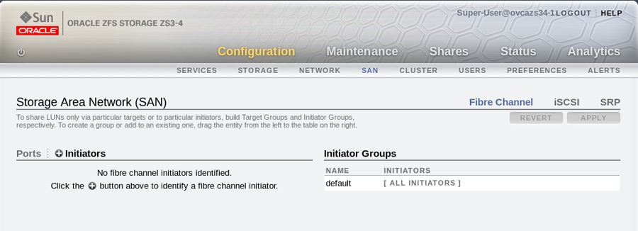
Configurationlink, then click on theSANlink. IfFibre Channelis not already selected, click on theFibre Channellink. The SAN Summary page is displayed.Click on the
+ Initiatorslink as indicated in the image below:The
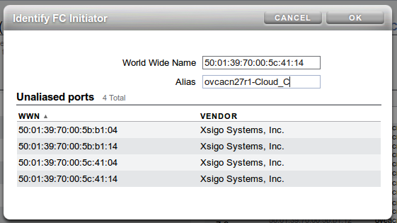
Identify FC
                Initiator
dialog opens and lists the WWPNs that the ZS3-4 is able to detect. You should create a user-friendly alias for each WWPN listed so that it is easy to identify how these map onto the nodes and clouds configured within the Oracle PCA. Use the Oracle PCA command line interface on the master management node to obtain a listing of all of these WWPNs and the recommended aliases that you should use. You can do this by running the pca-admin list wwpn-info command. Find the matching WWPN in theIdentify FC Initiatordialog and click on it to enter the recommended alias in the Alias field. Repeat this action for every WWPN. This step is illustrated in the figure below:When you have finished creating aliases for each WWPN, you can start to create the storage initiator groups where LUNs are presented later in the configuration. To create a new storage initiator group in the SAN Summary view, move your mouse over the left hand side of the WWN name until you see the
moveicon appear, then drag it to the right hand side of the screen and drop it in theCreate New Initiator Groupbox that appears. This step is illustrated in the figure below:Figure 7.5 Use the
SAN Summarypage to create a new storage initiator group by dragging an initiator across the page.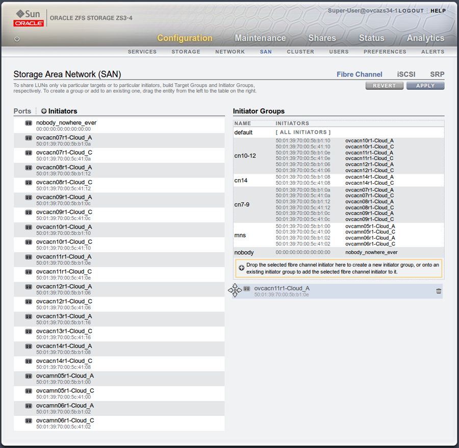
You can create as many initiator groups as you like. In most cases, if your storage is not used outside of the Oracle PCA and you do not need to segregate storage within the Oracle PCA, you can simply use the default initiator group. However, if your storage is shared with appliances outside of the Oracle PCA, you must, at least create an initiator group for all of the initiators that belong to nodes within the Oracle PCA. If you need to segregate storage further, you can create initiator groups that only include the initiators for particular compute nodes, as is illustrated in the screenshot.
Once you have created a new initiator group, you can roll over it using your mouse and then click on the edit icon that appears in the form of a pencil. A dialog appears where you are able to edit the initiator name to change it to something more appropriate. You can also select the rest of the initiators that you wish to include in the initiator group. Click when you have finished editing the initiator group.
When you have finished creating and editing initiator groups, it is important that you click on the button on the SAN Summary page to save the changes that you have made.
You can now define how LUNs map to your initiator groups depending on your requirements. This is achieved by clicking on the
Shareslink in the navigation bar at the top of the page. On theProject Summarypage, you can view any storage pools that you have defined and the LUNs associated with those pools. You can also create new LUNs for each storage pool as required. On this page, you can click to edit a LUN and edit the storage initiator groups that it is exposed to. In this view, you can make a LUN accessible to any of the storage initiators that you defined in the previous steps.
Since vHBAs are created on each compute node during the provisioning or upgrade process, the storage should be automatically refreshed within Oracle VM Manager as part of this process and the physical disks should be visible within Oracle VM Manager immediately. However, in the case that a disk is not displayed within Oracle VM Manager after the initial server discovery is performed, it is possible that you may need to rediscover the compute nodes so that Oracle VM Manager sees the vHBAs and the LUNs that are accessible to them. The following steps describe actions that should be performed in Oracle VM Manager to start making use of your newly attached FC storage in the case where these disks do not appear automatically within Oracle VM Manager.
Log into the Oracle VM Manager web-interface on the Oracle PCA.
Click on the
Servers and VMstab and select all of your compute node servers.Click on the
Rediscover Serversicon to rediscover all of your servers.After you have finished rediscovery, check that there are four new vHBAs for each server by clicking on the server in the navigation pane and then changing the perspective to
Storage Initiators.Click on the
Storagetab.Expand the
SAN Serversitem in the navigation pane and select theUnmanaged Fibre Channel Storage Array.Click on the
Editicon and navigate to theAdmin Serverstab in the dialog that appears.Add all of the compute node servers as admin servers for the storage array and click to close the dialog.
Click on the
Refresh SAN Servericon and click on the confirmation dialog.Wait for all of your servers to be updated. This operation can take several minutes to complete.
The LUNs display in the
Physical Disksperspective for theUnmanaged Fibre Channel Storage Array.You can check that the LUNs are also available to your servers on the
Servers and VMstab by clicking on a server and changing the perspective to thePhysical Disksview.