
InfiniBand can be used to connect additional ZFS Storage Appliances to the Oracle Private Cloud Appliance (PCA) using the available ports on the Fabric Interconnects. Since ZFS Storage Appliances are dual-headed, each ZFS Controller head has its own InfiniBand connection to each of the Fabric Interconnects, providing redundancy both on the side of the ZFS Storage Appliance and on the side of the Oracle PCA.
The recommended cabling configuration that should be implemented to connect the ZFS appliance to the Oracle PCA cross-connects each controller head to each of the Fabric Interconnects for a total of four connections. This configuration maximizes redundancy and throughput. The following table describes how the cabling should be connected between the Fabric Interconnects on the Oracle PCA and the ZFS Storage Appliance.
Table 7.3 InfiniBand Cabling to Attach a ZFS Storage Appliance
Top Oracle Fabric Interconnect F1-15 (RU 22-25): | Bottom Oracle Fabric Interconnect F1-15 (RU 15-18): | ZFS Storage Appliance Controller Head 1 | ZFS Storage Appliance Controller Head 2 |
|---|---|---|---|
IB Port 1 | IB Port 1 (ibp0) | ||
IB Port 11 | IB Port 1 (ibp0) | ||
IB Port 1 | IB Port 2 (ibp1) | ||
IB Port 11 | IB Port 2 (ibp1) |
This cabling layout is illustrated in the following figure, titled Figure 7.6, “IPoIB Storage Cabling Configuration”.

The following IP address blocks have been reserved for use by a ZFS Storage Appliance external to the Oracle PCA rack:
192.168.40.242
192.168.40.243
192.168.40.244
192.168.40.245
192.168.40.246
This section describes the configuration steps that you must perform on the ZFS Storage Appliance to use IPoIB in conjunction with the Oracle PCA. The description provided here assumes a typical configuration using iSCSI to serve LUNs to compute nodes or virtual machines as physical disks. The ZFS Storage Appliance supports a standard NFS configuration as well.
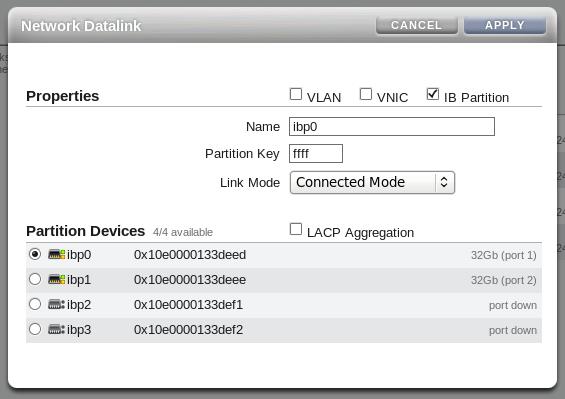
On each controller head, go to and to . If you have cabled correctly, there are two devices listed that are active and that map onto the cabled IB ports. Drag each of these across to the Datalink menu to create a new datalink for each device. You can edit each of these datalinks to provide a datalink name and partition key. Make sure that you repeat this step for each active device, and that you perform this step on each controller head.
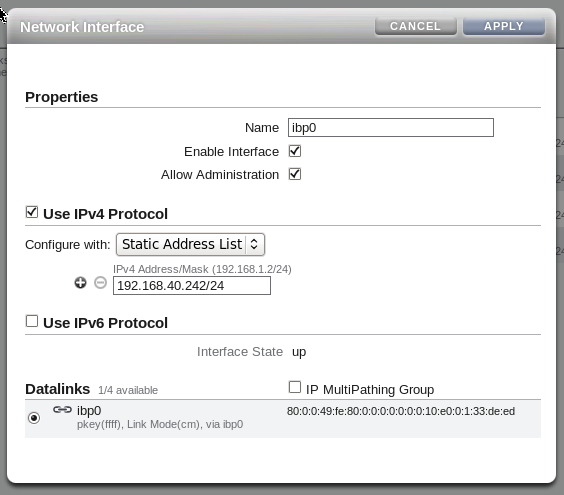
Drag each configured datalink across into the Interface menu to create an interface for each datalink that you have defined. Edit each interface to provide a value for the Name field that makes it easy to identify the interface. Add an IP address to the interface. On each controller head, use the IP address 192.168.40.242/24 for the port 1 (ibp0) and the IP address 192.168.40.244/24 for port 2 (ibp1). Leave the IP MultiPathing Group unchecked.
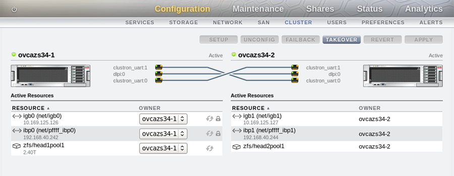
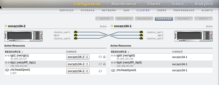
Configure your cluster settings by going to and to on each controller head. It is important to understand that for an active-active configuration you must have already created two separate pools before configuring the cluster. If you only have a single pool defined, you are only able to run the appliance in active-passive mode. The following screenshots illustrate an active-active configuration as viewed within the BUI on each controller head of the appliance:
An active-passive configuration with a single storage pool can be configured within the BUI of the sole active controller head on the storage appliance, with all interfaces assigned to the active controller head. This configuration is almost identical to the configuration used for the internal ZFS Storage Appliance that is included within the Oracle PCA rack.
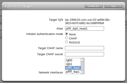
To configure iSCSI, you must go to , and then to in the BUI of one of the controller heads. Create a target for each interface defined for each controller head.
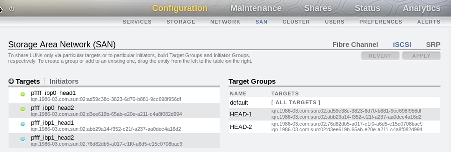
Drag the targets that you have created into the Target Group area in the BUI to create a target group for each controller head, as illustrated in the following screenshot.
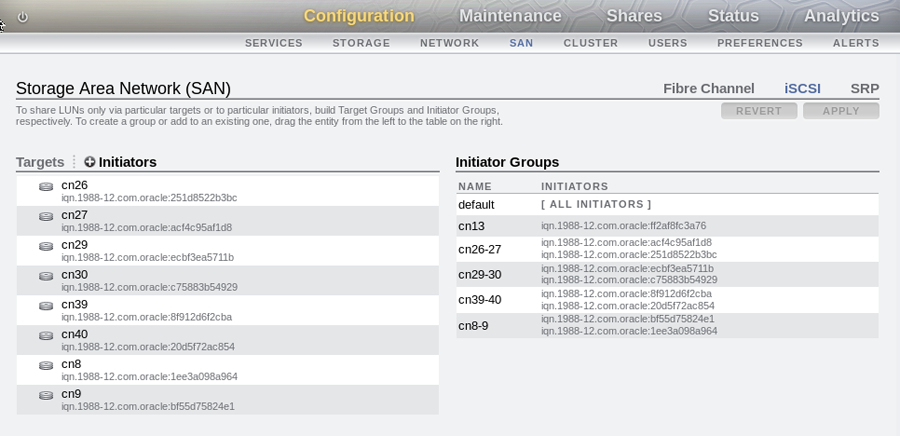
Click on the Initiators link to define the iSCSI initiators and initiator groups for the compute nodes that you wish to expose LUNs to. You can obtain initiator IQN values for each compute node from within Oracle VM Manager, in the Storage Initiator perspective for each Server. Initiator groups are created by dragging initiators from the Initiators area across to the Initiator Groups area within the BUI. The initiators that you choose to add and the initiator groups that you create depend entirely on your own requirements.
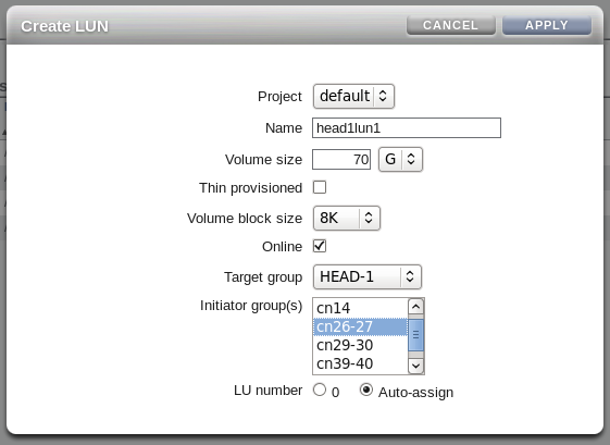
Create LUNs and assign them to the target groups and initiator groups that you have created.
If you wish to access these LUNs as physical disks within Oracle VM Manager, you must configure Oracle VM Manager first. Refer to Section 7.3.4.1, “ISCSI Configuration” for more information.
If you intend to use your ZFS appliance to provide storage for use directly by Oracle VM, to host repositories and virtual machines, you must configure the storage within Oracle VM Manager before you are able to use it. The configuration steps that you must perform depend on whether you have configured iSCSI or NFS on your ZFS Storage Appliance. This section provides a brief outline of the steps that you must perform to configure Oracle VM Manager for each of these technologies. For more detailed information, you should refer to the Oracle VM documentation.
If you only intend to make this storage available to individual virtual machines and do not intend to use the storage for underlying Oracle VM infrastructure, you do not need to perform any of the steps documented in this section, but you will need to configure each virtual machine directly to access the storage either over NFS or iSCSI.
The following configuration steps should be performed in Oracle VM Manager if you have configured your storage appliance for iSCSI. The process to add a File Server in Oracle VM Manager is clearly documented in the Oracle VM User's Guide for Release 3.2 available at:
http://docs.oracle.com/cd/E35328_01/E35332/html/vmusg-storage-manage.html
Log into Oracle VM Manager on the Oracle PCA
Select the
Storagetab to configure your storageClick on the
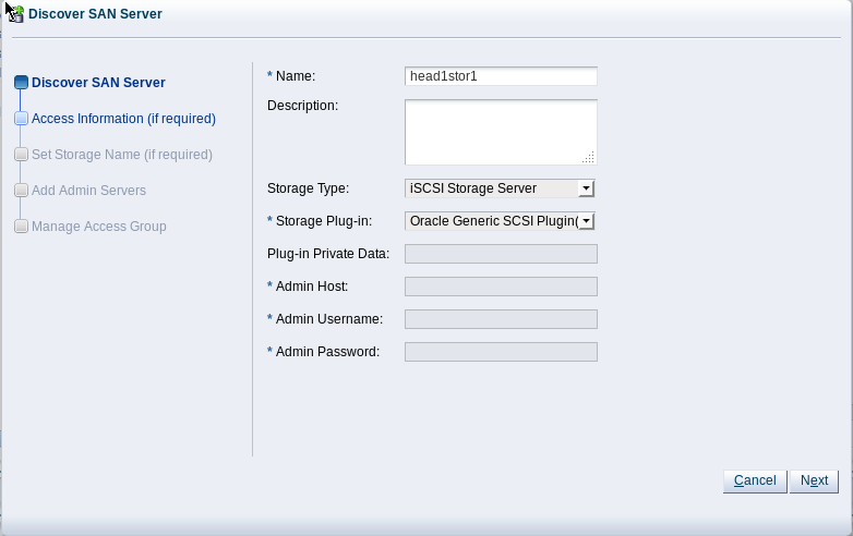
Discover SAN Servericon to load the wizardEnter the DNS name of the storage appliance in the Name field. In the Storage Type field, use the drop-down selector to select
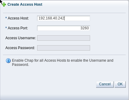
iSCSI Storage
              Server
. In the Storage Plug-in field, you must select theOracle Generic SCSI plugin. Note that alternate storage plugins are not supported in this configuration. Click .In the Access Information dialog, click on the icon that allows you to add a new Access Host. This opens the Create Access Host dialog. Enter the first IP address that you configured for the device as the Access Host IP, for example 192.168.40.242. If you have configured your storage appliance with CHAP access, you must also enter the CHAP username and password here. Click to close the Create Access Host dialog. Repeat this step to add a second Access Host for the second IP address that you have configured on the storage appliance, for example 192.168.40.243. When you have finished adding Access Hosts, click .
In the Add Admin Servers dialog, select all of the servers in the Available Servers frame and move them to the Selected Servers frame. Click .
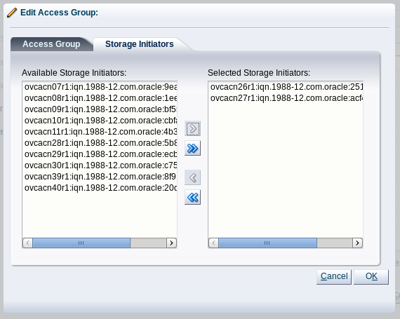
In the Manage Access Group dialog, click on
Default Access Groupand then click on the Edit icon. The Edit Access Group dialog is opened. Click on theStorage Initiatorstab. At minimum, select the IQN name from all of the initiators that you have configured on the ZFS Storage Appliance and move them into the Selected Storage Initiators pane. Usually it is acceptable to move all of the IQNs across. Click to save the changes.Click the button to exit the wizard and to save your changes.
The iSCSI server appears in the SAN Servers tree in the navigation pane.
The following configuration steps should be performed in Oracle VM Manager if you have configured your storage appliance for NFS. The process to add a File Server in Oracle VM Manager is clearly documented in the Oracle VM User's Guide for Release 3.2 available at:
http://docs.oracle.com/cd/E35328_01/E35332/html/vmusg-storage-manage.html
Log into Oracle VM Manager on the Oracle PCA
Select the
Storagetab to configure your storageClick on the
Discover File Servericon to load the wizardEnter all required information into the wizard. Use either one of the IP addresses that you configured for the device as the Access Host IP, for example 192.168.40.242.
Select all of the compute nodes that should be designated as Admin Servers.
Select two or three compute nodes that should be used as Refresh Servers.
Select the file systems that you would like to use.
Click the
Finishbutton.The file server appears in the File Servers tree in the navigation pane.