Cabling Disk Shelves Together
Use the following procedure to cable disk shelves together in a rack. For DEx-24P disk shelves, use one-meter (3.28-foot) cables; and for DEx-24C and Sun Disk Shelves, use two-meter (6.56-foot) cables. The maximum allowable cable length between disk shelves is three meters (9.84 feet).
- Locate the appropriate cabling diagram for your system in Getting Started with Cabling.
-
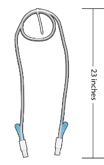
Starting in the middle of a disk shelf cable, make the appropriate number of
loose 12.7-centimeter (5-inch) diameter loops, and attach a cable tie to secure
them as shown in the following illustration.
Use these guidelines for creating the loops:
-
1-meter cable length - 2 loops
-
2-meter cable length - 3 loops
-
3-meter cable length - 4 loops
The length between the cable tie and the cable ends should be approximately 0.58 meters (23 inches).
-
-
Facing the rear of the rack and starting with the uppermost disk shelf, hold
the cable loops to the side of the rack, choosing the side closest to the disk
shelf cabling ports.
The cable tie should face the rear of the rack to maximize the cable length.
- Extend the upper end of the cable to the rack rail above the uppermost disk shelf, and ensure that the cable leaves enough clearance to remove the power supply.
-
Connect that cable end to the appropriate port in the uppermost disk
shelf.
Refer to the appropriate cabling diagram to identify the disk shelf port. When attaching a cable to a DEx-24 disk shelf, position the blue release tab correctly for the disk shelf type and I/O Module, and ensure that the cable connector latches engage in the port.
Attaching a Mini-SAS HD Cable to a DE3-24P Disk Shelf
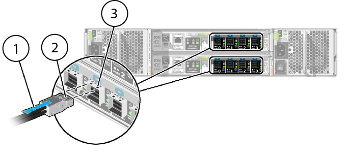 CalloutDescription1Blue release tab2Cable connector latches3IOM 0/IOM 1 port latch receiver holes
Attaching a Mini-SAS HD Cable to a DE3-24C Disk Shelf
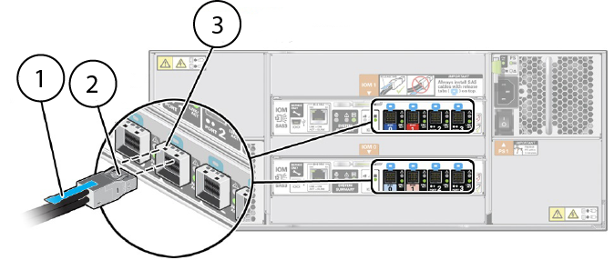 CalloutDescription1Blue release tab2Cable connector latches3IOM 0/IOM 1 port latch receiver holes
Attaching a Mini-SAS Cable to a DE2-24P Disk Shelf
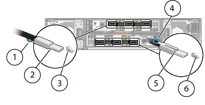 CalloutDescription1Blue release tab2Cable connector latches (underneath)3IOM 1 port latch receiver holes (underneath)4Blue release tab5Cable connector latches6IOM 0 port latch receiver holes
Attaching a Mini-SAS Cable to a DE2-24C Disk Shelf
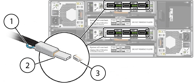 CalloutDescription1Blue release tab2Cable connector latches (underneath)3IOM 0/IOM 1 port latch receiver holes (underneath)
 - Slide the coiled cable between the vertical rack rail and the rack side panel, ensuring that the cable tie is still facing the rear of the rack.
- Verify clearance for power supply removal, and then connect the other end of the cable to the appropriate port in the appropriate disk shelf.
-
Use another cable tie to secure the upper end of the cable to a rack rail
mounting hole that is slightly above the uppermost disk shelf.
Cabling 2U Disk Shelves Together (DE3-24P shown)
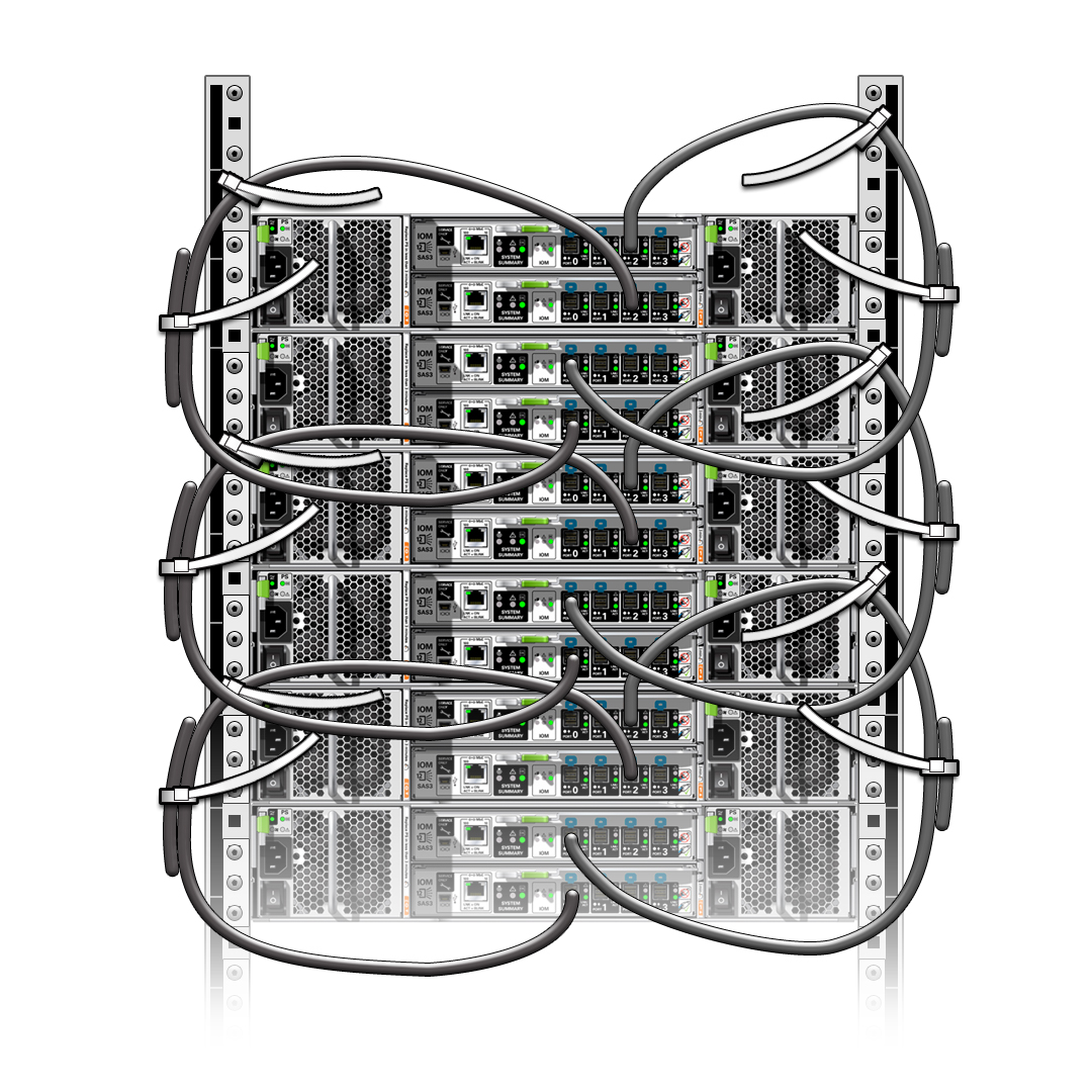
Cabling 2U Disk Shelves Together (DE2-24P shown)
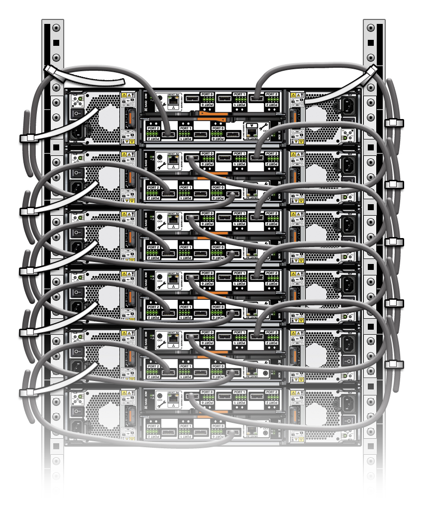
Cabling 4U Disk Shelves Together (DE3-24C shown)
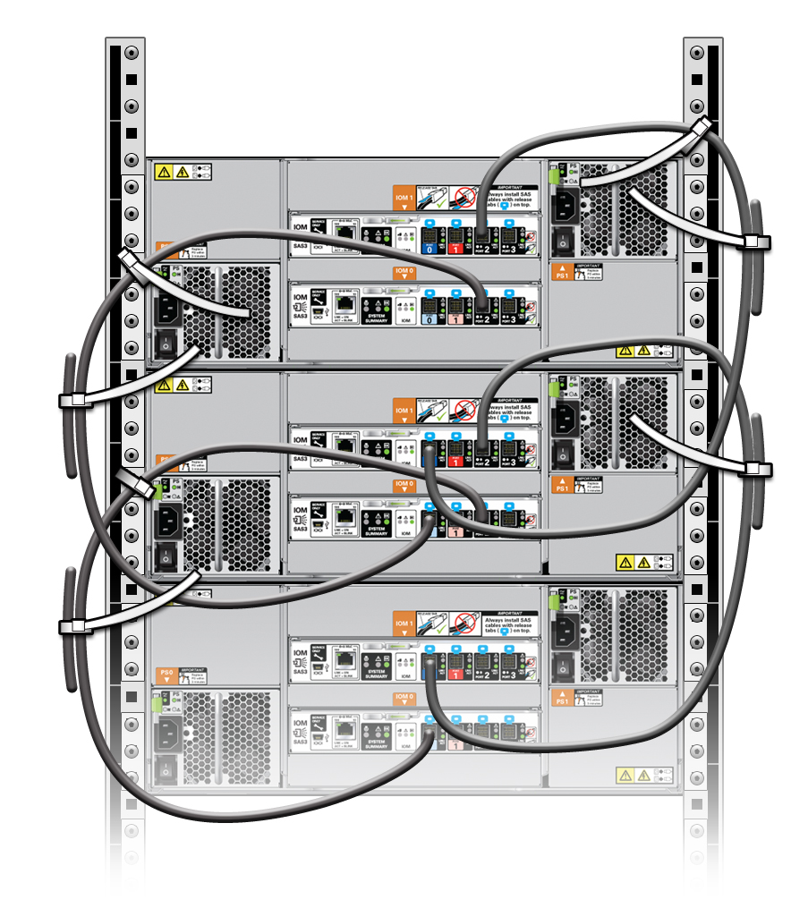
Cabling 4U Disk Shelves Together (DE2-24C shown)
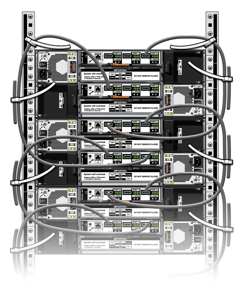
-
Repeat this process for the remaining disk shelves in the chain, substituting
the correct disk shelves.
Keep approximately 20.32 centimeters (8 inches) between cable tie-offs on a side.
- (Optional) Trim the cable tie excess.
- Repeat this procedure for any additional disk shelf chains.
- To connect the controllers to the disk shelf chains, see the appropriate procedure: