2 Planning for the Hardware Installation
Library Configuration Guidelines to Maximize Performance
-
Place the Base Module in the center of the library string.
-
Place a balance of Cartridge Modules to the left and the right of the Base Module.
-
Spread the Drive Modules out within the library string to reduce robot contention.
-
If only adding one Access Module for bulk loading, place the module on the left side of the library string.
-
When installing additional CAPs, balance the CAPs between the left and right sides of the library string. If partitioning the library, install enough CAPs to provide at least one CAP for each partition. This allows each partition to contain a dedicated CAP.
-
Install enough tape drives to adequately handle peak workload. Logically group tape drives and compatible tapes together.
-
Pre-install physical capacity to grow into it non-disruptively.
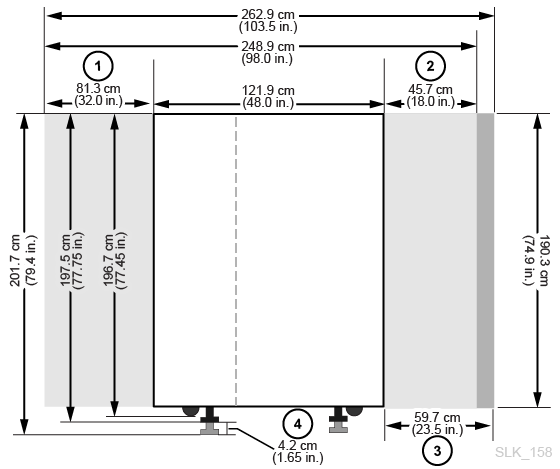
Library Dimensions and Weights
-
Base and Drive Module rear service clearance
-
Base and Drive Module front service clearance
-
Access Module service clearance
-
Weight pad adjustment range
-
Side cooling area
-
Side cover
-
Nozzle cutout for fire suppression system
-
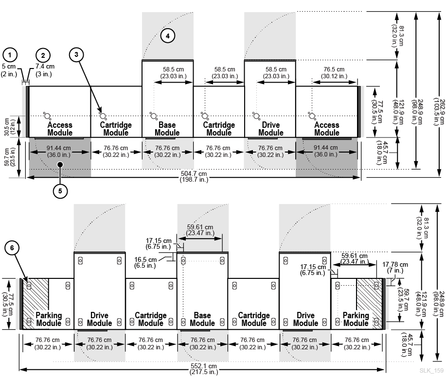
Base Module and Drive Module service clearance (light gray areas)
-
Access Module service clearance (dark gray areas)
-
Weight distribution pad
Base Module Measurements
| Dimension | Measurement |
|---|---|
| Height | 196.7 cm (77.45 in.) on casters for transport
197.5 cm (77.75 in.) to 201.68 cm (79.4 in.) on weight pads for permanent install |
| Width | 76.8 cm (30.22 in.) when placed between modules
81.3 cm (32 in.) transport width (no side covers) Foot 1 91.5 cm (36 in.) standalone with side covers on both sidesFoot 2 |
| Depth | 121.9 cm (48 in.) |
| Service Area | Front: 45.7 cm (18.0 in.)
Rear: 81.3 cm (32.0 in.) Side Cooling Area: 5 cm (2 in.) Side Install Area: 45.7 cm (18.0 in.) |
| Weight | Frame only: 357 kg (786 lb)
8 drives and tapes: 618 kg (1362 lb) 16 drives and tapes: 656 kg (1447 lb) 24 drives and tapes: 682 kg (1504 lb) Side Covers: 18.5 kg (41 lb) per side |
Footnote 1 81.3 cm is the minimum transportation clearance because alignment tabs on each side of the module add 4.5 cm to the 76.8 cm width.
Footnote 2 One side cover adds 7.4 cm (2.9 in.) to the module width. Only the ends of the library require side covers.
Drive Module Measurements
| Dimension | Measurement |
|---|---|
| Height | 196.7 cm (77.45 in.) on casters for transport:
197.5 cm (77.75 in.) to 201.68 cm (79.4 in.) on jack pads for permanent install |
| Width (module only) | 76.8 cm (30.22 in.) when placed between modules
81.3 cm (32 in.) transport width (no side covers) Foot 1 83.8 cm (33 in.) with one side cover |
| Depth (doors closed) | 121.9 cm (48 in.) |
| Service Area | Front: 45.7 cm (18.0 in.)
Rear: 81.3 cm (32.0 in.) Side Cooling Area: 5 cm (2 in.) Side Install Area: 45.7 cm (18.0 in.) |
| Weight | Frame only, no CAP: 265 kg (584 lb)
8 drives and tapes: 540 kg (1190 lb), 582 kg (1284 lb) with CAP 16 drives and tapes: 596 kg (1314 lb), 621 kg (1369 lb) with CAP 24 drives and tapes: 647 kg (1426 lb), 660 kg (1456 lb) with CAP 32 drives and tapes: 709 kg (1564 lb), 723 kg (1594 lb) with CAP |
Footnote 1 81.3 cm is the minimum transportation clearance because alignment tabs on each side of the module add 4.5 cm to the 76.8 cm width.
Cartridge Module and Parking Module Measurements
| Dimension | Measurements |
|---|---|
| Height | 196.7 cm (77.45 in.) on casters for transport
197.5 cm (77.75 in.) to 201.68 cm (79.4 in.) on jack pads for permanent install |
| Width (module only) | 76.8 cm (30.22 in.) when placed between modules/side cover
81.3 cm (32 in.) transport width (no side covers) Foot 1 83.8 cm (33 in.) with one side cover |
| Depth | 77.5 cm (30.5 in.) |
| Weight (Cartridge Module) | Frame only: 175 kg (385 lb)
Installed, with tapes: 340 kg (749 lb) |
| Weight (Parking Module) | Frame only: 175 kg (385 lb)
Installed, with tapes: 257 kg (567 lb) |
Footnote 1 81.3 cm is the minimum transportation clearance because alignment tabs on each side of the module add 4.5 cm to the 76.8 cm width.
Access Module Measurements
| Dimension | Measurement |
|---|---|
| Height | 196.7 cm (77.45 in.) on casters for transport
197.5 cm (77.75 in.) to 201.68 cm (79.4 in.) on jack pads for permanent install |
| Width | 91.4 cm (36.0 in.) when placed between module and side cover
96 cm (37.8 in) transport width (no side covers) Foot 1 99.1 cm (39 in.) with one side cover |
| Depth | 77.5 cm (30.5 in.) |
| Service Area | Front: 59.7 cm (23.5 in.) |
| Weight | Frame only: 204.2 kg (450 lb) |
Footnote 1 96 cm is the minimum transportation clearance because alignment tabs on each side of the module add 4.5 cm to the 91.5 cm width.
Covers, Doors, and Service Clearances
| Dimension | Measurement |
|---|---|
| Height | 190.3 cm (74.9 in.) frame only |
| Door thickness | Front: 1.9 cm (0.75 in.)
Back: 4.5 cm (1.75 in.) |
| Door latches | 2.53 cm (0.9 in.) |
| Service clearance | Front: 45.7 cm (18 in.) for Base and Drive Module only, 59.7 cm (23.5 in.) for Access Module
Back: 81 cm (32 in.) for Base and Drive Module only Side: 5 cm (2 in.) for cooling, 45.7 cm (18.0 in.) for install |
| Side cover | 7.4 cm (2.9 in.) width
18.5 kg (41 lb) each |
Shipping Weights and Dimensions
The SL4000 library modules and other components are shipped on pallets. The table below lists each module and its shipping specifications. If equipment on a pallet must be transported on elevators, the elevator cars must be capable of safely handling the weight.
| Component | Height | Width | Depth | Weight |
|---|---|---|---|---|
| Base Module | 213.3 cm (84 in.) | 99 cm (39 in.) | 159.3 cm (62.7 in.) | 433 kg (954 lb) |
| Drive Module | 213.3 cm (84 in.) | 99 cm (39 in.) | 159.3 cm (62.7 in.) | 381 kg (839 lb) |
| Cartridge/Parking Module | 215 cm (84.7 in.) | 99 cm (39 in.) | 100.7 cm (39.6 in.) | 250 kg (552 lb) |
| Access Module | 215 cm (84.7 in.) | 113 cm (44.6 in.) | 100.7 cm (39.6 in.) | 290 kg (640 lb) |
| LTO drive tray | 32 cm (12.6 in.) | 31 cm (12.2 in.) | 66 cm (26 in.) | 9.5 kg (20.9 lbs) |
| T10000 drive tray | 34 cm (13.4 in.) | 31 cm (12.2 in.) | 66 cm (26 in.) | 10.5 kg (23.1 lbs) |
| Drive array | 48.3 cm (19 in.) | 65.5 cm (25.75 in.) | 83.8 cm (33 in.) | 24.5 kg (54 lbs) |
| CAP | 32 cm (12.6 in.) | 39.4 cm (15.5 in.) | 135.4 cm (54.5 in.) | 32.7 kg (72 lbs) |
| Redundant robot | 63.2 cm (24.9 in.) | 46.7 cm (18.4 in.) | 196.9 cm (77.5 in.) | 35 kg (77 lbs) |
| PDU | 41.3 cm (16.25 in.) | 32.7 cm (12.9 in.) | 44.7 cm (17.6 in.) | 7.7 kg (17 lbs) |
| Power Supply | 14 cm (5.5 in.) | 29 cm (11.4 in.) | 40 cm (15.7 in.) | 4 kg (8.8 lbs) |
| Power Cord | 10.2 cm (4 in.) | 31.8 cm (12.5 in.) | 31.8 cm (12.5 in.) | 1.6 kg (3.5 lbs) |
Pallets have a pallet-ramp design to provide safe removal of the module at the customer site. The modules have wheels to allow for easy positioning. Once positioned, the installer must raise the modules from their wheel-base to rest upon weight-plates for stability and leveling.
Installation Site Requirements
Physical Space Requirements
The library requires adequate physical space and a service area. Ensure that the components can pass through doorways and fit in elevators (see "Library Dimensions and Weights"). If you plan on adding modules in the future, ensure there is enough space.
The suggested library adjustment height is 200 cm (77.6 in.). Ensure the top of the library does not interfere with ceiling fixtures at the installation site.
Floor Requirements
You can install the library on a raised, solid, or carpeted floor if there is adequate airflow.
-
Raised floor — ensure there are no ventilation panels directly below the library.
-
Solid floor — route the cables from the ceiling to avoid creating a tripping hazard.
-
Carpeted floor — ensure the carpet is approved for computer-room equipment and provides protection from electrostatic discharge (ESD).
Weight
Verify the site floor can support the weight of the library. It must support 454 kg (1,000 lb) per weight distribution pad. There are four distribution pads per module (see Figure 2-2).
If using an elevator to transport the equipment, verify it can safely handle the weight (see "Shipping Weights and Dimensions").
Floor Slope
Robots must travel along a level plane throughout the library. Any excessive out-of-plane conditions could cause binding, premature wear, and damage to the robots. The library weight pads adjust to account for minor slope. However, you should ensure that the floor does not have excessive slope before installation.
Environmental Requirements
For optimal reliability, maintain the environment between the recommended ranges.
| Description | Temperature | Relative Humidity (non-condensing) | Wet Bulb Maximum | Maximum Altitude |
|---|---|---|---|---|
| Operating | 15 to 32°C (60 to 90°F) dry bulb | 20% to 80%Foot 1 | 29.2°C (84.5°F) | 3.05 km (10,000 ft) |
| Storage | 10 to 40°C (50 to 104°F) | 10% to 95% | 35.0°C (95.0°F) | 3.05 km (10,000 ft) |
| Shipping | -40 to 60°C (-40 to 140°F) | 10% to 95% | 35.0°C (95.0°F) | 15.24 km (50,000 ft) |
Footnote 1 Oracle recommends maintaining a relative humidity of 40% to 50%.
Airborne Contaminants
Airborne particulates can damage tape libraries, drives, and tapes. The operating environment for the tape library must meet to the following requirements:
-
ISO 14644-1 Class 8 Environment
-
Total mass of airborne particulates must be less than or equal to 200 micrograms per cubic meter
-
Severity level G1 per ANSI/ISA 71.04-1985
Particles ten microns or smaller are particularly harmful to most data processing hardware. Gasses that are particularly dangerous to electronic components include chlorine compounds, ammonia and its derivatives, oxides of sulfur, and petrol hydrocarbons. In the absence of appropriate hardware exposure limits, health exposure limits must be used.
Humidification with chlorinated water is a common source of airborne chlorine. Appropriately-designed carbon filters must be used to ensure safe levels of airborne chlorine when chlorinated water is used for humidification.
Table 2-1 Gas Limit Recommendations
| Chemical | ASHRAE | OSHA (PEL) | ACGIH | NIOSH |
|---|---|---|---|---|
|
Acetic Acid (CH3COOH) |
Not defined |
10 ppm |
Not defined |
Not defined |
|
Ammonia (NH) |
3500 µg/m3 |
350 ppm |
25 ppm |
Not defined |
|
Chlorine (Cl) |
2100 µg/m3 |
31 ppm (c) |
Not defined |
0.5 ppm (c) |
|
Hydrogen Chloride (HCl) |
Not defined |
5 ppm (c) |
Not defined |
Not defined |
|
Hydrogen Sulfide (H2S) |
50 µg/m3 |
320 ppm (c) |
10 ppm |
10 ppm |
|
Ozone (O3) |
235 µg/m3 |
30.1 ppm |
Not defined |
Not defined |
|
Petrol-hydrocarbons (CnHn) |
Not defined |
500 ppm |
75 ppm |
300 ppm |
|
Sulfur Dioxide (SO2) |
80 µg/m3 |
35 ppm |
2 ppm |
0.5 ppm (c) |
|
Sulfuric Acid (H2SO4) |
Not defined |
1 ppm |
Not defined |
1 ppm (c) |
Some basic precautions to follow:
-
Do not allow food or drink into the data center.
-
Do not store cardboard, wood, or packing materials in the data center clean area.
-
Identify a separate area for unpacking new equipment from crates and boxes.
-
Do not allow construction or drilling in the data center without first isolating sensitive equipment. Dry wall and gypsum are especially damaging to equipment.
Seismic or Earthquake Ratings
The requirements for seismic compatibility vary dramatically throughout the world. Therefore, Oracle does not offer a standard "seismic" feature for the SL4000 library. If you have seismic concerns, Oracle recommends that you work with local experts who are familiar with the local code and requirements. Professional Services can also help coordinate this activity.
CAUTION:
You must consult a qualified seismic engineer to verify seismic zone exposures and adequate site preparation.For sites in areas of seismic activity, you might want to permanently fix the library position for added stability. The library has mounting holes in the floor of each module where you can use half-inch carriage bolts (mounting studs) to permanently fix the library's position.
Power Requirements
Waste Disposal
Plan for the disposal of all packing material. Determine if waste bins or recycling containers will be provided on site or whether an independent company will handle the disposal at additional cost.
Fire Suppression Planning
The library does not ship with a fire suppression system, but each module has a 5 cm (2 inch) diameter circular nozzle opening (see Figure 2-2). To custom fit the nozzles, you can drill openings in the cover plates (each plate is 7 cm (2.75 inch) square and 1.2 mm (0.048 inch) thick). Professional Services can assist with fire suppression planning.
IMPORTANT:
Nozzles must remain clear of robotic operations and cannot protrude more than 1.9 cm (0.75 inches) into the library.You can connect the library to your Emergency Power Off (EPO) system using the connector in the Base Module safety controller card (see "Safety Controller (LON)").
Networking
Oracle recommends a dedicated and secure private network for communication between the library and host software. A secure private network connection using an Ethernet hub or switch is required for maximum throughput and minimum resource contention. Switches must be set to auto negotiate. Each external library port must be on a separate subnet. If network ports are on the same subnet, you will only be able to reach one port
The library reserves IP addresses 192.168.0.0/11. Avoid using addresses in the range 192.168.0.0/11 for any external interface.
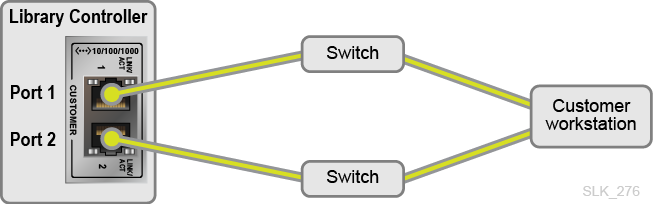
Connect to Both Customer Ports on the Library Controller for Redundancy
If using dual TCP/IP, connect each customer port to a physically separate, non-stacked switch. Connecting both customer ports to a single physical switch or single logical switch may cause the customer network ports to stop functioning.
The following diagram shows an example configuration where the "customer workstation" could be a system running a browser to connect to the library GUI or a server running an application that directly uses the SCI interface to control the library.
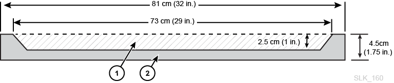
Cable Routing
The top and bottom of the Base and Drive Module rear door have openings to allow for cable routing. The openings are 2.5 cm (1 inch) by 73 cm (29 inches).
Note:
The rear door has two square holes near the bottom on the face of the door. These are for access to the PDU on/off switch, not for cable routing.When routing cables, make sure to include locations for power, library control, and Ethernet cables. As a best practice, route power cables through one opening and signal cables through another opening.
-
Cable routing area
-
Overhead view of back door
AC Power Cables
Make sure to plan for the locations of power cables and list the locations for their associated circuit breakers. Order appropriate cables for the power configuration (see "AC Power Source Options").
Library Network Cables
You can place the library in a 62.5-micron-cable Storage Area Network (SAN). However, the cable that connects the library to the network must be a 50-micron cable.
Maximum supported cable distance depends on the link speed, the type of fiber (50 or 62.5 micron), and the device the library is attached to. The typical distances are:
-
8 Gbps = up to 21 m (69 ft) for 62.5-micron, 50 m (164 ft) for 50-micron
-
4 Gbps = up to 70 m (230 ft) for 62.5-micron, 150 m (492 ft) for 50-micron
-
2 Gbps = up to 150 m (492 ft) for 62.5-micron, 300 m (984 ft) for 50-micron
-
1 Gbps = up to 175 m (574 ft) for 62.5-micron, 500 m (1640 ft) for 50-micron
If your library attaches to a host bus adapter (HBA), refer to the HBA's documentation for the supported cable distances.
Approximate Installation Time
The times listed below do not include library initialization, testing, audits, and feature upgrades. Contact an Oracle sales representative for more information.
| Module/Component | Time Estimate (hours) | Personnel Required | Total Person Hours |
|---|---|---|---|
| Base with 8 drives (standard) | 3 | 2 | 6 |
| Drive Module (each) | 2 | 2 | 4 |
| Cartridge Module (each) | 2 | 2 | 4 |
| Two Parking Modules | 2 | 2 | 4 |
| Access Module (each) | 2 | 2 | 4 |
| CAPs (each) | 1 | 2 | 2 |
| Tape drive (each drive) | 0.5 | 1 | 0.5 |
| Firmware | 0.2 | 1 | 0.2 |
| Integration (cables, hubs, switches, connections) | 8 | 1 | 8 |
| Tapes (each) | 0.02 | 1 | Varies |
| Software configuration | 2 to 8 | 1 | Varies |
Initial Configuration Wizard Information
Before powering on the library for the first time, gather the following library configuration information. You will need the following information to complete the initial configuration wizard of the library GUI.
-
IPv4 or IPv6 information for the public port, service port, and OKM port (if using OKM). Each port must be on a different subnet.
-
For IPv4, determine the IP address, netmask, and gateway
-
For IPv6, determine the IP address, prefix length, and gateway
-
-
HTTP (default 80) and HTTPS (default 443) listening ports
-
Library time zone:
-
Determine if using UTC or regional
-
Determine if using NTP server or setting the time manually
-
-
Library name
-
Determine desired system cell label format (see "Volume Label Format Options")
-
OPTIONAL: DNS information for the library controller public port:
-
Domain name
-
Up to three DNS server addresses
Caution:
If using DNS, verify all DNS server information is correct and that the Customer Port has a valid link before configuration. Invalid DNS information can cause library startup to take 2 hours. -
Initial Configuration Steps After Physically Installing the Library
After physically installing the modules and tape drives, use the following list as a guideline for initial library configuration and connecting to SCSI host applications.
What to do before a library power up or restart
-
Connect Ethernet cables to the library controller Customer port, and optionally connect to the Service and OKM ports.
-
Install the tape drives (if not already installed). Connect Fibre Channel cables to all drives. DO NOT connect Ethernet cables to individual drives. The drive IP network is internal to the library.
-
If using FC-SCSI host applications, connect Fibre Channel cables to the library controller ports. Initially, only port 1 is fully active (see "Behavior of an Unavailable Fibre Channel Port").
What to do after the library powers up and completes initialization
-
Verify the LINK light is active on the FC switches for the tape drives and the library controller connection. The library controller does not have FC link lights. To verify the connection, you must check the FC switch or use the GUI (see "Is the FC connection working? There is no LINK light.").
-
Install hardware activation files: redundant control path and tape capacity as appropriate (see "Add or Remove Optional Library Features").
-
OPTIONAL: Partition the library (see "Partitioning the Library"). Create CAP pools ("Manage CAP Pools"). Create partitions and assign cells to partitions ("Move Storage Cells and Drive Bays to a Partition").
-
Load tapes using the CAP (if not done before power up).
-
For shared CAPs, you must assign ownership to a partition before importing tapes ("Assign Ownership of a Shared CAP to a Partition")
-
Open the CAP, load tapes, and use the GUI to move the tapes out of the CAP (see "Enter Tapes Through a CAP").
-
How to remotely access the library's tape drives
-
You will need to configure a separate admin server to remotely access the drives. You will use this admin server for OKM drive enrollment, VOP 2.3.3 operations, IBM drive encryption firmware upgrades, and drive firmware upgrades.
-
The SL4000 drive network differs from that of the SL3000, and therefore requires different routing. Refer to the OKM documentation for the OKM SL4000 setup information.
-
After configuring the admin server, try pinging an SL4000 drive using the drive's IP address as found in the GUI (see "IP Addressing of Drives").
How to connect SCSI host applications to the library
-
Verify that the library and drive FC ports are logged into the FC switches. Zone the FC switch so that the drives and library robots will be available to host applications. At this point, the hosts should be able to see the drives.
-
Verify the hosts appear in the GUI (see "View Actively Logged-In SCSI Hosts"). In the GUI, the World Wide Port Name (WWPN) is the WWPN of the host HBAs. Rename the hosts ("Add, Modify, or Delete a SCSI Host").
-
More "hosts" than expected may appear in the list. These are most likely FC switch ports. After identifying them, you may rename or ignore these "hosts".
-
-
Assign partitions (see "Assign Partitions to a SCSI Host and Alter LUN Assignment"). Each host must have one and only one LUN 0 per host port.
-
The host applications should now be able to see the robots.
-
Configure the host applications. For example, install necessary patches to support the SL4000 library, setup the devices (paying attention to the drive order, which may be the SCSI addressing order), inventory the tapes, and so on.