1 Library Overview
Oracle's StorageTek SL4000 modular library system is an enterprise tape storage solution that offers flexibility, scalability, and high availability. The SL4000 is modular to meet the demands of rapidly growing and constantly changing environments.
Library Modules Overview
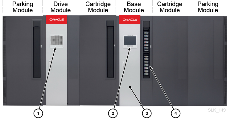
There can be a maximum of 15 modules per library (one Base Module and up to 14 expansion modules). The module types are:
-
Perforated window
-
Operator panel
-
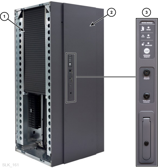
Base Module front door
-
Rotational CAP (rotary CAP)
Base Module
-
One Base Module is required per library. A standalone Base Module is the smallest possible configuration.
-
For best performance, place the Base Module at the center of the library.
-
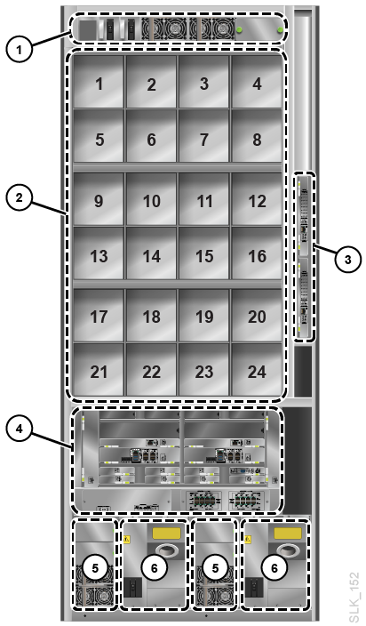
Comes standard with a rotational CAP, operator panel, one drive array (8 drive bays), two LTO drives, one PDU, two DC drive power supplies, and two DC rail power supplies. The library does not come with SFPs.
-
The Base Module contains the card cage. It ships standard with one library controller, a root switch, three library storage cards, a video card, two DC converters, two fan assemblies, safety controller, and network patch panel. For more information, see "Base Module Card Cage".
-
Optional second and third drive array (for 24 drive bays max).
-
Optional web camera.
-
Optional feature card.
-
205 to 431 tape capacity depending on the number of drive arrays (see "Calculating Physical Capacity").
-
Rail power module (contains up to three DC power supplies and two rail controllers)
-
Tape drive bays
-
Drive switch card cage (contains up to two drive network switches, slot 1 on the bottom and slot 2 on top)
-
Base card cage
-
Drive DC power supplies
-
Power distribution units
Drive Module
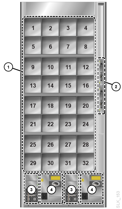
The Drive Module increases the number of drive bays and provides additional tape storage.
-
Maximum of three Drive Modules per library placed anywhere.
-
Comes standard with one drive array (8 drive bays). The rear of the Drive Module contains drive bays, PDUs, DC power supplies, and a drive switch.
-
Optional second, third, and fourth drive array (for 32 drive bays max).
-
Optional rotational CAP (see "Rotational Cartridge Access Port (CAP)").
-
Optional web camera.
-
153 to 522 tape capacity depending on options selected (see "Calculating Physical Capacity").
-
Tape drive bays
-
Drive switch card cage (slot 1 on the bottom and slot 2 on top)
-
Drive DC power supplies
-
Power distribution units
Cartridge Module
The Cartridge Module provides additional storage cells.
-
The maximum number of Cartridge Modules depends on the other modules present. The library is limited to 15 modules total. For example, if the library has a Base Module and two Drive Modules, the library can support up to 12 Cartridge Modules.
-
Optional rotational CAP (see "Rotational Cartridge Access Port (CAP)").
-
438 to 620 tape capacity each (see "Calculating Physical Capacity").
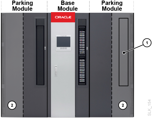
Parking Module
A Parking Module is a Cartridge Module with a modified module id block (see "Module Identification Block"). The library only requires Parking Modules in a redundant robotics configuration when the library does not have Access Modules.
Six columns (three on the front wall and three on the back wall) are inaccessible and cannot contain tapes (see Figure B-9 and Figure B-10). The library "parks" a defective robot in this area without blocking access for the operational robot (see "Robotics"). You do not need to remove the inaccessible cartridge arrays. The module can be restored to a Cartridge Module at anytime by changing the module id block.
Note:
Performing maintenance on a disabled robot in a Parking Module disrupts library operations. For non-disruptive robot maintenance, use Access Modules instead (see "Access Module").-
230 to 312 tape capacity (see "Calculating Physical Capacity").
-
Only the left Parking Module can have an optional CAP. The CAP area of the right Parking Module is inaccessible to the robot.
-
Must be installed on each end of the library.
-
Inaccessible CAP area, CAP vacancy plate
-
Robot parking area (inaccessible tape cells)
Access Module
An Access Module has a cartridge access door used for bulk loading of up to 234 tapes. Additionally, a library with two Access Module supports the redundant robotics feature (see "Robotics"). A sliding safety door in the Access Module can separate a defective robot from the rest of the library, allowing a service representative to access the disabled robot while the library remains online.
Note:
Access Modules and Parking Modules cannot be installed in the same library.-
Access Modules must be placed on the ends of the library.
-
A single Access Module supports bulk loading capabilities only. You should install a single Access Module on the left for an additional 104 storage cells (see "Calculating Physical Capacity").
-
Dual Access Modules support bulk loading and redundant robotics.
-
Side cover removed showing sliding door
-
Bulk load cartridge access door
-
Access module service panel and handle
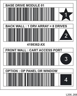
Module Identification Block
Each module has a module identification block that the robot scans during the first library startup or during a startup where you have selected Probe for Configuration Changes (see "Library Settings Options"). The id block lists the module type and module options, such as a CAP or the number of drives. For the location of the module identification block, see the "Cell Maps".
Hardware Components Overview
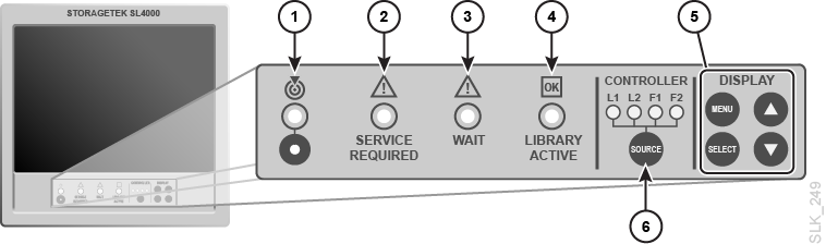
Operator Panel
The front of the Base Module contains the operator panel. It consists of a touch screen to access the GUI and a series of indicators and buttons on a control panel below the screen.
-
Locator light — blinks when you activate the locate function from the GUI.
-
Service action required indicator — the library is inoperable and requires maintenance.
-
Wait indicator — the library is going to an offline state. Do not enter the library until this indicator is off.
-
Library active indicator — the library has power and is running.
-
LCD display controls — used to adjust the monitor settings, such as brightness and contrast.
-
SOURCE (display toggle) — switches the display signal routing between the controllers or feature cards. If the display is currently at the VGA port, the initial press will toggle it to the front touch screen and subsequent presses will cycle through the controllers. L1 and L2 are the library controllers. F1 and F2 are feature cards.
Base Module Card Cage
The rear of the Base Module houses the card cage, which contains controller cards, disk storage, cooling fans, switches, and power converters. The main controller card is the library controller. The configuration that ships standard is shown below.
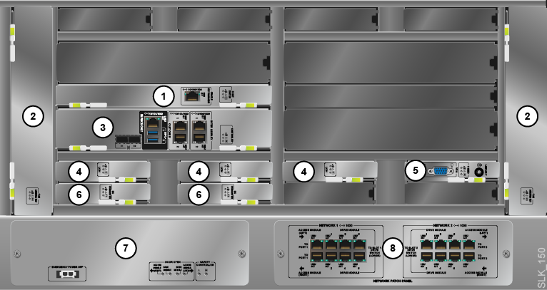
You can optionally add up to two feature card upgrade kits to the Base Card Cage. Each kit contains two Storage Controller cards, a DC Power Converter, and a Feature Card. The locations of the feature card upgrade components are shown below.
You can use the feature card kit to run application software such as SDP 2.4.
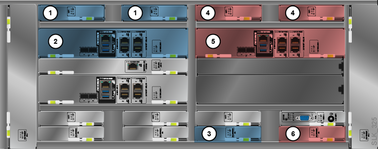
Feature Card Kit 1
1. Feature Storage Card (physically the same as Library Controller Storage (LOH))
2. Feature Card (physically the same as the Library Controller (LOC))
3. DC Power Converter (LOY)
Feature Card Kit 2
4. Feature Storage Card (physically the same as Library Controller Storage (LOH))
5. Feature Card (physically the same as the Library Controller (LOC))
6. DC Power Converter (LOY)
Controller Card Indicators
Most controller cards in the Base card cage have the same three indicator lights.
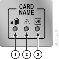
-
Ok to remove device (blue)
-
Service action required (yellow)
-
Power to device (solid green)
Library Controller (LOC)
The library controller is the main controller card in the library. It contains the ports used for the host connection and service maintenance. There are two FC ports and two Ethernet ports used for host connectivity. For more information, see "Host Connectivity Options".
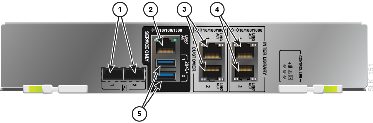
-
FC ports (these do not have a LINK light — see "Is the FC connection working? There is no LINK light."). The library controller does not ship with SFP modules, you must purchase those separately.
-
Service network port
-
Customer network ports 1 and 2
-
Inter-library network ports (not used in the SL4000)
-
USB ports (for keyboard and mouse)
DC Power Converter (LOY)
Converts 48V DC from the power supplies to 12V DC. For more information, see "Power Configuration Overview".

Library Controller Storage (LOH)
A hard drive that stores information for the library software. The library comes standard with three storage cards and the data is mirrored on each.

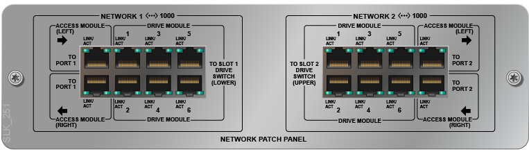
Network Patch Panel (LOEB)
The Ethernet bulkhead that connects the Drive Module's drive switches and the Access Module's controllers to the Base Module. There are two networks: Network 1 and Network 2. For each network there are six Drive Module Ethernet ports and two Access Module Ethernet ports.
Root Switch (LOER)
The root switch provides connectivity to the drive switches, robot network, and controller cards. It contains one Ethernet port to connect to the Oracle Key Manager network used for drive encryption (see the Oracle Key Manager (OKM) documentation for more information). For port configuration information, see "Configure the Public Network, Service Network, or OKM Ports".
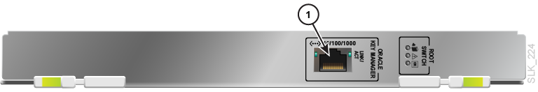
-
Oracle Key Manager (OKM) network port
Safety Controller (LON)
Monitors the status of all the library doors and cuts power to the rail when any door opens unexpectedly. This card has a battery so that it can report "Door Has Been Opened" status if any door opens while the library has no power.
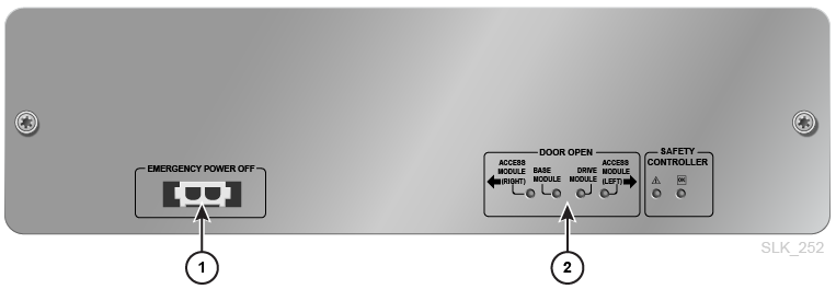
-
Emergency shut off — connects to the customer's emergency power off (EPO) system generally through an external switch (installed by the customer) which cuts power to the library in an emergency.
The connector is a two pin Universal Mate and Lock connector (TYCO 770024-1 with female contacts TYCO 770010-3). To connect to this port, you can use TYCO 770017-1 with male contacts TYCO 770009-1 (or equivalent part numbers).
-
Door open — indicates if a module has an open front access door
Video Card (LOV)
The video card indicates which controller is displayed on the front touch screen or on a separate monitor connected to the VGA port.
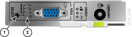
-
SELECT (display toggle) — switches the display signal routing between the controllers or feature cards. If the display is currently at the front touch screen, the initial press will toggle it to the VGA port and subsequent presses will cycle through the controllers.
-
Controller card indicator — L1 and L2 are the library controllers. F1 and F2 are feature cards. You can cycle through which controller is displayed by pressing the SELECT button.
Supported Tape Drives
The SL4000 library supports the following tape drive types. The Base Module comes standard with two LTO drives. You must purchase additional drives through Oracle or upgrade the drives from a legacy Oracle library.
-
StorageTek T10000 (all models)
-
HP LTO Generations 5 and 6
-
IBM LTO Generations 5, 6, 7, and 8
Note:
LTO-8 drives can read and write one generation back. LTO-5, 6, and 7 drives can read two generations back and write one generation back. For best capacity and performance, always use cartridges of the same generation as your drives.Tape Drive Encryption
There are two encryption key management options:
-
Application-managed — an application manages the keys using the data path.
-
OKM-managed — Oracle Key Manager (OKM) appliance manages the keys using an Ethernet connection outside the data path which is generally more secure. For more information on encryption, refer to the drive documentation and the Oracle Key Manager (OKM) documentation.
Support for application-managed and OKM-managed encryption depends on the drive type.
T10000 Encryption
All T10000 generations are encryption-ready, however enabling either application-managed or OKM-managed encryption requires a T10K-EKEY-A-N encryption activation permit. You can order an encryption activation permit at any time (during initial purchase or afterward). After purchasing the permit, use Virtual Operator Panel (VOP) to enable encryption (see the VOP documentation on the Oracle Technical Network). T10000C and T10000D drives no longer require encryption license keys to enable encryption
LTO Encryption
OKM-managed encryption requires an LTO-ENCRYPT-ACTIVE encryption activation permit. Application-managed encryption using the data path does not require a permit.
HP LTO 5 and 6 drives support both OKM-managed and application-managed encryption. IBM LTO 5, 6, and 7 drives require a Belisarius card in the drive tray to interface with OKM. You may purchase a drive with or without OKM compatibility. To upgrade a non-OKM-compatible drive, you can purchase a kit to add the Belisarius card.
Re-using Encryption Activation Permits
If you previously purchased an activation permit for an older drive, you can re-use the activation permit when upgrading to a newer generation drive in the same family, as long as the total number of encryption enabled drives does not exceed your total number activation permits for that family. For example, if you have six T10K-EKEY-A-N activation permits, you can only have a total of six encryption-enabled T10000 drives (regardless of generation).
Supported Tape Cartridges
All tapes must have a readable external label (see "Barcode Labels Overview" for label requirements). The library will not import or mount a non-labeled or unknown tape type (anything other than LTO or T10000). Tape types include:
-
Data — stores customer data
-
Diagnostic — used by service representatives to run read/write tests on drives and run diagnostic tests (label starts with DG[space])
-
Cleaning — cleans the tape path and read/write heads of the drives (label starts with CLN)
Drive Trays
A drive tray houses a tape drive and contains the drive controller card which allows the drive to interface with the library. The drive tray slides into a drive bay of a drive array. Often "tape drive" and "drive tray" are synonymous.
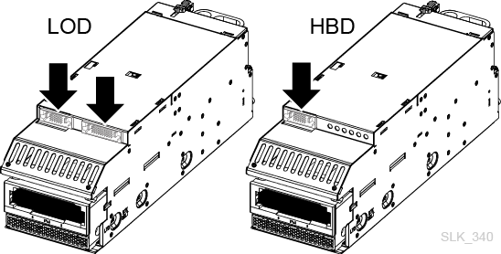
You can use an SL3000 drive tray in an SL4000 if the tray contains the SL4000 controller LOD card. The SL3000 drive controller HBD card is not supported. You can easily identify the tray type by noting the number of ports on top of the tray. The SL3000 HBD card has one port and the LOD has two ports.
Note:
The rear drive tray Ethernet ports are disabled in the SL4000.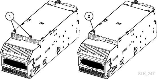
-
LOD tray with SL4000 port and SL3000 port
-
HBD tray with SL3000 port only
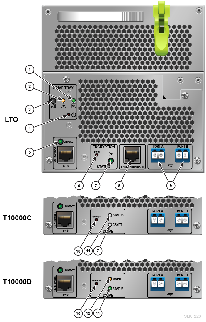
-
Power to drive (solid green). Power to tray only or installing code (blinking green).
-
Service action required (yellow)
-
Okay to remove drive tray from library (blue). Flashes when you use the locate feature (see "Physically Locate a Drive Using the Locator LED").
-
Power to tray on/off (push button) — Disabled on the SL4000. Instead use the GUI to turn the tray on or off (see "Turn a Drive On or Off").
-
Ethernet link (green). The port is disabled on the SL4000 and only used by Oracle service representatives for maintenance.
-
Encryption reset to default IP address (push button)
-
Encryption indicator
-
Encryption card port. The port is disabled on the SL4000.
-
Fiber channel ports
-
Maintenance push button (DO NOT USE in the SL4000. It will take the drive offline.)
-
Drive status indicator
-
Drive maintenance indicator
Drive Switch
The drive switch connects the drive trays to the rest of the library. The connection between the switch and the drive trays is internal, so you no longer need to connect Ethernet cables to individual drives.
The Base Module and each Drive Module contains a drive switch card cage, which holds up to two drive switches (see Figure 1-2 and Figure 1-3). The Base Modules comes standard with one drive switch and the Drive Module comes standard with two drive switches. However, only one drive switch in the Drive Module is operational until you install a second root switch in the Base Module.
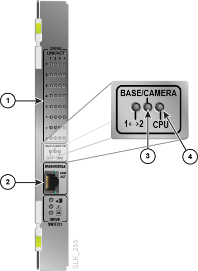
-
Drive tray connection indicators — each LED corresponds to a drive bay location. An active LED indicates the drive tray is installed and communicating with the library.
-
Ethernet port used to connect the Base Module's network patch panel to each Drive Module. Leave this port unconnected in the drive switches of the Base Module.
-
In the Base Module, this LED indicates there is an active connection between the network patch panel and the drive switch. In the Drive Module, this LED indicates there is an active connection between the drive switch and the web camera (if installed).
-
Indicates that the onboard processor for the drive switch is operational.
Robotics
Robots retrieve and insert tapes into CAPs, storage cells, and drives. Robots move along two rails on the back wall of the library. Copper strips in the top rail provide power and a signal path between the robot and the library controller. Power is supplied from +48 VDC 1200 W load-sharing supplies in the rail power module (see "DC Power Supplies").
Robots contain a barcode scanner that identifies volume serial numbers (volsers) of tapes during CAP entries and library audits. The scanner also reads the module identification blocks in each module during library initialization.
Each library can have either one (standard) or two robots (known as redundant robotics). The optional redundant robotics feature increases library efficiency and allows library operations to continue if one robot fails. Redundant robotics requires 2N power (see "Power Redundancy Options") and either two Parking Modules or two Access Modules.
Rotational Cartridge Access Port (CAP)
A rotational CAP (referred to as rotary CAP in the GUI) is a vertically-mounted, rotating cylinder with two removable 13-cell magazines.
-
The Base Module comes standard with a CAP.
-
Each Drive Module or Cartridge Module can have one optional CAP per module. Only the left parking module can contain a CAP. The CAP on a right parking module is inaccessible.
-
Each CAP has a keypad with an unlock indicator and a button to open the CAP (see "Open or Close a CAP Using the GUI").
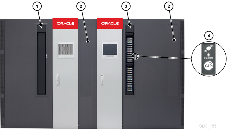
-
CAP (closed)
-
No CAP installed
-
CAP (open)
-
Keypad
Bulk Load Cartridge Access Ports (Access Module)
Using the Access Module you can to enter and eject up to 234 tapes. Only one Access Module is required to support the bulk loading feature (see "Access Module").
Web Camera
You can optionally add a web camera to the Base Module or Drive Module to remotely see inside the library. The camera mounts on the interior of the module access door. See "View the Inside of the Library Using the Web Camera".
Cooling
The library contains cooling fans for the following components:
Fan Assembly
The library comes standard with two fan assemblies in the Base Module card cage that provide cooling for the electronics in the card cage (see "Base Module Card Cage" for the location). The library controller monitors these fans for proper operation. The fault indicator on the fan assembly indicates a failure. The assembly can be replaced without interfering with library operations.
Optional Library Features
Features that Require an Activation File
Some optional library features require you to purchase and install a hardware activation file. See "Add or Remove Optional Library Features".
Activated Tape Cartridge Capacity
Capacity activation files determine the number of tapes allowed in the library. Tapes in system cells do not count toward licenced capacity. If the library contains more tapes than the activated capacity, it will continue to function normally, however, it is illegal to use non-activated capacity. Either eject tapes or purchase and install another capacity activation file (see "How to Fix a Tape Count Warning").
Multiport Networking (Redundant Control Paths)
Multiport networking activates the second FC port and second customer Ethernet port on the library controller. This feature requires you to purchase and upload Redundant Control Paths activation file (see "Host Connectivity Options").
Features that Do Not Require an Activation File
You can validate the integrity of T10000 tapes using media validation.You must assign T10000C or D drives to the "Media Validation" partition/pool to enable media validation. The partition does not contain tapes, and hosts cannot access the drives in the media validation partition. The library uses the drives in the partition to evaluate the integrity of T10000 tapes. Use the GUI to configure the drive partition (see "Add or Remove Drives from the Media Validation Partition (Pool)").
Library partitioning reserves library resources (drives, storage cells, and CAPs) for the exclusive use of specific StorageTek Library Control Interface (SCI) and FC-SCSI hosts. The SL4000 supports up to 16 partitions. Partitioning is an optional feature that comes standard with the library, but is disabled by default. You can enable partitioning in the library settings (see "Configure the Library with the Configuration Wizard").
See "Web Camera".
Storage Capacity Overview
There are two types of capacity:
-
Physical Capacity — the number of storage cells in the library, excluding reserved system cells. Physical storage capacity can range from 300 to 9,017 cells and 1 to 120 drives.
Note:
Oracle recommends adding physical capacity in advance to meet future storage needs. Although modules can be added at any time, adding a module is disruptive to library operations. -
Activated Capacity — the number of tapes allowed in the library as defined by the cumulative amount of capacity hardware activation files installed on the library. Use the GUI to install the capacity activation files (see "Add or Remove Optional Library Features"). Unlike the SL3000, the SL4000 does not designate active and inactive cells. The capacity activation files only limit the total number of tapes allowed in the library. The total tape count displayed in the GUI excludes tapes in the system cells.
Note:
If the library contains more tapes than installed capacity activation files, the library will continue to function. However, it is illegal to use unactivated capacity. Either eject tapes or purchase and install another capacity activation file (see "How to Fix a Tape Count Warning").
Calculating Physical Capacity
Use the table below to calculate the storage cell capacity of a library (excluding system cells). For each module in the library, start with the standard cell count. Then, either add or subtract based on the module's position and add-on options. Finally, add the cell counts of each module together to get the total capacity of the library.
Table 1-1 Storage Cell Capacity Per Module
| Physical Configuration | Base Module | Drive Module | Cartridge Module | Parking Module | Access Module |
|---|---|---|---|---|---|
|
Standard |
339 |
378 |
516 |
308 |
0 |
|
2nd Drive ArrayFoot 1 |
-55/-66 |
-55/-66 |
-- |
-- |
-- |
|
3rd Drive ArrayFootref 1 |
-60/-72 |
-60/-72 |
-- |
-- |
-- |
|
4th Drive ArrayFootref 1 |
-- |
-65/-78 |
-- |
-- |
-- |
|
Module to Left |
+88 |
+88 |
+104 |
+4 |
0 |
|
Module to Right |
+13 |
+51 |
0 |
0 |
-- |
|
CAP |
Std. |
-39/-77 Foot 2 |
-78 |
-78Foot 3 |
-- |
Footnote 1 For additional drive arrays, the first number listed is the change in capacity when there is no module to the left, and the second number is the change in capacity when there is a module to the left.
Footnote 2 The -39 is the change in capacity when there is no module to the right, and -78 is the change in capacity when there is a module to the right.
Footnote 3 For left Parking Module only.
Capacity Calculation Example 1
The example library has a Parking Module, Drive Module, Cartridge Module, Base Module, Cartridge Module, and Parking Module (see Figure 1-1).
- Left Parking Module
-
Contains a CAP. There is a module to the right.
308 (standard) - 78 (CAP) + 0 (module to right) = 230
- Drive Module
-
Contains a CAP and four drive arrays. There is a module to the right and left.
378 (standard) – 78 (CAP with module to right) – 66 (2nd drive array) – 72 (3rd drive array) – 78 (4th drive array) + 52 (module to right) + 88 (module to left) = 224
- Left Cartridge Module
-
There is a module to the right and left.
516 (standard) + 0 (module to right) + 104 (module to left) = 620
- Base module
-
Contains three drive arrays. There are modules to the right and left.
339 (standard) – 66 (2nd drive array) – 72 (3rd drive array) + 13 (module to right) + 88 (module to left) = 302
- Right Cartridge Module
-
Contains a CAP. There is a module to the right and left.
516 (standard) – 78 (CAP) + 0 (module to right) + 104 (module to left) = 542
- Right Parking Module
-
308 (standard) + 4 (module to left) = 312
- Library Total
-
230 (Parking Module) + 224 (Drive Module) + 620 (Cartridge Module) + 302 (Base Module) + 542 (Cartridge Module) + 312 (Parking Module) = 2,230
Capacity Calculation Example 2
The example library has a Base (in center) and seven Cartridge Modules on each side of the Base (15 modules total). This represents the maximum storage capacity for an SL4000.
- Base module
-
Contains one drive array. There is a module to the right and left.
339 (standard) + 13 (module to right) + 88 (module to left) = 440
- Cartridge Modules
-
Left-most Cartridge Module: 516 (standard) + 0 (module to right) = 516
Right-most Cartridge Module: 516 (standard) + 104 (module to left) = 620
All other Cartridge Modules: 516 (standard) + 104 (module to left) + 0 (module to right) = 620
- Library Total
-
440 (Base) + 516 (left-most Cartridge Module) + 620 (right-most Cartridge Module) + 12 x 620 (other Cartridge Modules) = 9,016
Capacity Calculation Example 3
The example library has a Cartridge Module, Base Module, Drive Module, another Cartridge Module, and a single Access Module on the right for bulk loading. Oracle does not recommend installing a single Access Module on the right. If the Access Module was installed on the left end of the library, 104 additional cells would be accessible in the far left Cartridge Module.
- Left Cartridge Module
-
Module is on the left end of the library. There is a module to the right.
516 (standard) = 516
- Base module
-
Contains two drive arrays. There are modules to the right and left.
339 (standard) + 13 (module to right) + 88 (module to left) – 66 (2nd drive array) = 374
- Drive Module
-
Contains three drive arrays. There is a module to the right and left.
378 (standard) + 13 (module to right) + 88 (module to left) – 66 (2nd drive array) – 72 (3rd drive array) = 341
- Right Cartridge Module
-
This is a module to the right and left.
516 (standard) + 0 (module to right) + 104 (module to left) = 620
- Access Module
-
Module is on the right end of the library (not recommended for single Access Module).
0 (standard) = 0
- Library Total
-
516 (left Cartridge Module) + 374 (Base) + 341 (Drive Module) + 620 (right Cartridge Module) + 0 (Access Module) = 1,851
Power Configuration Overview
All power supplies and power distribution units (PDUs) reside in the Base Module and Drive Modules (each module ships standard with one PDU). When selecting a power configuration, consider any power redundancy requirements along with the features and number of drives in the library.
Power Redundancy Options
There are three power configurations that offer various levels of power redundancy.
| Configuration | AC Power | DC Power | Feature Support |
|---|---|---|---|
| N+1 (standard) | No redundancy
One PDU per Base or Drive Module |
Provides one extra drive DC supply and one extra robotics DC supply | Limited support for T10000 drives and no redundant robotics support |
| 2N | Redundant
Two PDUs per Base or Drive Module |
Provides a set of DC power supplies for each PDU | Required for redundant robotics and redundant electronics support
Full support for T10000 drives. |
| 2N+1 | Redundant
Two PDUs per Base or Drive Module |
Provides additional power supplies for each PDU, meaning N+1 DC power redundancy for each PDU (except the second PDU only has N DC power supply redundancy for the robot) | Supports redundant robotics and redundant electronics
Full support for T10000 drives. |
AC Power Source Options
Each PDU in the library requires a separate AC power source with:
-
240 VAC, 50/60 Hz, at 30 amps (range: 200–240 VAC, 47–63 Hz, 24 amps), single phase
AC Power Cables
-
N+1 — order one power cord for the Base module and an additional power cord for each Drive Module
-
2N or 2N+1 — two power cords for the Base module and two additional power cords for each Drive Module
| Power Cord - Length/Type | Power Source | Circuit Breaker | Wall Connector | Library Connector |
|---|---|---|---|---|
| US 3.7 m (12 ft) 12 AWG | 240 VAC/30A | 30A | L6-30P | L6-30R |
| International 4 m (13 ft) HAR | 240 VAC/30A | 30A | 330P6W | L6-30R |
DC Power Supplies
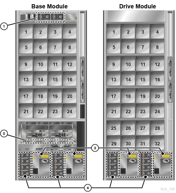
-
Rail DC power supplies (1200W DC)
-
DC power converters
-
PDUs (240 VAC)
-
Drive DC power supplies (1200W DC)
Base Card Cage DC Power Converters
The DC converters in the card cage (see "Base Module Card Cage" for location) convert 48VDC from the drive DC power supplies to 12VDC. These converters replace the functionality of the cPCI power supplies in the SL3000. Each Base Module ships standard with two DC converters.
A minimum card cage configuration (one controller, one root switch, three storage cards, one video card, and one fan assemblies) requires a minimum of two DC converters for N+1 and three for 2N or 2N+1 redundancy.
A maximum card cage configuration (four controllers, two root switches, seven storage cards, one video card, and two fan assemblies) requires a minimum of three DC converters for N+1 and four for 2N or 2N+1 redundancy.
Rail Power Supplies
The robots use load-sharing 1200 W DC power supplies located at the top of the Base Module (the Drive Module does not contain rail DC supplies) — see Figure 1-13. The rail DC power supply are physically the same power supply used for the drives.
Each Base Module ships standard with two rail DC power supplies used for N+1 and 2N configurations. You must order a third DC power supply for the 2N+1 configuration.
Tape Drive Power Supplies
The drives use load-sharing 1200 W DC power supplies. Up to four power supplies are located to the left of each PDU in both the Base and the Drive Module — see Figure 1-13.
The library ships standard with two drive power supplies per Base and two per Drive Module. The number of additional power supplies required depends on the library configuration (see "Calculating Power Supply Quantities" below).
Calculating Power Supply Quantities
The number of power supplies required depends on:
-
Power configuration (N+1, 2N, or 2N+1)
-
Base card cage configuration
-
Number and type of drives (T10000 and LTO)
To determine the number of power supplies to order for your library configuration:
-
Determine the maximum power consumption of the card cage (see "Card Cage Power Consumption").
-
Calculate the maximum power consumption of the drives:
-
Determine the number of each drive type and multiply by the watts-per-drive for each drive type (see "Drive Power Consumption").
-
Add together the watts used by each drive type to calculate the total watts consumed.
-
-
Add the card cage and drive power consumptions together. See "DC Power Supplies Required for the Base Module" and "DC Power Supplies Required for the Drive Module" to determine the number of DC power supplies needed.
Card Cage Power Consumption
| Configuration | Maximum Watts |
|---|---|
| Minimum (one controller, one root switches, three storage cards, one video card, and two fan assemblies) | 352 |
| Mid (two controllers, two root switches, three storage cards, one video card, and two fan assemblies) | 511 |
| Maximum (two controllers, two feature cards, two root switches, seven storage cards, one video card, and two fan assemblies) | 793 |
Drive Power Consumption
| Drive Type | Watts Used by Each Drive |
|---|---|
| T10000A/B/C | 91 |
| T10000D | 117 |
| LTO | 48 |
DC Power Supplies Required for the Base Module
| Total Watts Used by All Drives | Power Supplies Required for N+1 | Power Supplies Required for 2N | Power Supplies Required for 2N+1 |
|---|---|---|---|
| 1 - 1,063 | 2 | 2 | 4 |
| 1,064 - 2,263 | 3 | 4 | 6 |
| 2,264 - 3,463 | 4 | 6 | 8 |
| 3,464 - 3,805 | 5 | 8 | 8 |
DC Power Supplies Required for the Drive Module
| Total Watts Used by All Drives | Power Supplies Required for N+1 | Power Supplies Required for 2N | Power Supplies Required for 2N+1 |
|---|---|---|---|
| 1 - 1,200 | 2 | 2 | 4 |
| 1,201 - 2,400 | 3 | 4 | 6 |
| 2,401 - 3,600 | 4 | 6 | 8 |
| 3,601 - 4,443 | 5 | 8 | 8 |
Example: Calculating Required Number of DC Power Supplies
The example library has a Base and one Drive Module with both drive types (T10000 and LTO). The Base has the minimum configured card cage (352W).
Base Module Drive Power Consumption Example
| Drive Type | Quantity of Drives | Multiply by Watts Per Drive | Total Watts Per Drive Type |
|---|---|---|---|
| T10000D | 6 | 117 | 702 |
| T10000C | 6 | 91 | 546 |
| LTO8 | 4 | 48 | 192 |
Total Drive Consumption for Base = 702 + 546 + 192 = 1,440 W
Drive Module Drive Power Consumption Example
| Drive Type | Quantity of Drives | Multiply by Watts Per Drive | Total Watts Per Drive Type |
|---|---|---|---|
| T10000C | 10 | 91 | 910 |
| LTO7 | 4 | 48 | 192 |
Total for Drive Module = 910 + 192 = 1,102 W
The Base consumes 1,792W (352 W for card cage and 1,440 W for drives). The Drive Module consumes 1,102 W.
The tables below list the power supplies required for the example library. Two tape drive DC power supplies ship standard with the Base and two power supplies ship standard with the Drive Module. Therefore, subtract two from the DC supplies required when determining what to order.
DC Supplies Required for Base Example
| Library Power Configuration | DC Supplies Required | DC Supplies to Order (= Required - 2) |
|---|---|---|
| N+1 | 3 | 1 |
| 2N | 4 | 2 |
| 2N+ 1 | 6 | 4 |
DC Supplies Required for Drive Module Example
| Library Power Configuration | DC Supplies Required | DC Supplies to Order (= Required - 2) |
|---|---|---|
| N+ 1 | 2 | 0 |
| 2N | 2 | 0 |
| 2N+1 | 4 | 2 |
The number of DC supplies that you need to order depends on the power configuration. For instance, if the example library had a 2N+1 configuration, it would require an order of six additional DC power supplies (four supplies for the Base and two supplies for the Drive Module). The 2N+1 also requires an additional DC supply for the rail. Therefore, you would need to order a total of seven DC power supplies
Calculating Total Power Consumption
For environmental or economical reasons, you might want to determine the total power consumption (Watts), CO2 emission values, and British Thermal Units (Btu/hr) for the library and drives.
| Components | Quantity | Idle Watts | Max Watts |
|---|---|---|---|
| Base Library (required)
Includes: card cage, 1 robot, 1 CAP, operator panel |
1 | 301 | 518 |
| Redundant Robotics (optional) | 1 | 48 | 154 |
| Additional CAPs (optional) | Each | 10 | 14 |
| Drive Module/Cartridge Module | Each | 3 | 5 |
| Access Module | Each | 9 | 29 |
| T10000A/B/C | Each | 61 | 93 |
| T10000D | Each | 64 | 127 |
| LTO | Each | 30 | 46 |
Calculating Total Watts, CO2 Emissions, and Btu/hr
To calculate the total power consumption in Watts for the library, add up all the applicable wattage values for the library configuration.
To calculate kilograms of CO2 emissions per day, multiply watts by the CO2 emissions constant. Use the constant that is applicable for your country (0.02497 for US).
To convert electrical values to Btu/hr, multiply the number of watts by 3.412 (1 W = 3.412 Btu/hr).
| Component | Quantity | Watts |
|---|---|---|
| SL4000 Base | 1 | 518 |
| LTO8 Tape Drives | 16 | 736 |
| Library Total | -- | 1,254 |
-
Emissions: 1,254W x 0.02497 = 31.3 Kg of CO2
-
Power consumption: 1,254W x 3.412 = 4,279 Btu/hr
| Component | Quantity | Watts |
|---|---|---|
| SL4000 Base | 1 | 518 |
| T10000D Tape Drives | 8 | 1,016 |
| Drive Module | 1 | 5 |
| T10000C Tape Drives | 8 | 744 |
| Cartridge Module | 1 | 5 |
| CAPs (3 at 10 Watts each) | 3 | 30 |
| Library Total | -- | 2,318 |
-
Emissions: 2,318W x 0.02497 = 57.9 Kg of CO2
-
Power consumption: 2,318W x 3.412 = 7,909 Btu/hr
Host Connectivity Options
The SL4000 library supports two types of host connections:
-
Small computer system interface (SCSI) over a physical Fibre Channel interface
-
Ethernet using 10/100/1000 Base-T and CAT 5e/1Gb cable
FC-SCSI Connection
The library comes standard with two FC ports (1 and 2) on the library controller card. However, by default only port 1 is fully active. Activating port 2 requires the Redundant Control Paths activation file. The library supports simultaneous access using both FC ports. However, the application using the SCSI interface must manage these connections. You must use a multi-path device driver or an application that is aware of the multiple paths.
See the SL4000 SCSI Reference Guide for more information on the SCSI command set, FC operations, topologies, and command implementations.
The library controller does not ship with SFP modules, you must purchase those separately.
TCP/IP Connection
The library controller provides two separate Ethernet connections (labeled as customer ports) on the library controller for communication with client applications.
-
Port 1 provides the primary host connection (standard).
-
Port 2 provides the dual connection (known as dual TCP/IP). Activation of this port requires the Redundant Control Paths activation file. Enabling dual Ethernet bonds the two ports into a single interface, requiring only one IP address for the pair of ports on each library controller card. Dual TCP/IP prevents a loss of connection between the library and host by automatically avoiding a failed port.
Library Management Applications
Software Vendors (ISVs)
-
Oracle Hierarchical Storage Manager (HSM)
-
Oracle Secure Backup
-
Hewlett Packard Enterprise Data Protector
-
Commvault Software
-
Dell/EMC NetWorker
-
IBM Spectrum Protect
-
Veritas Netbackup
-
DIVA
Not every application is tested on every platform or version. To verify the software is supported, contact an Oracle sales representative or application vendor.
Ordering
Contact Sales Assistance at +1.888.672.2534.
You must order tape cartridges separately. You can use existing tapes if they are compatible and still within their warranty period. Professional Services and Data Center Services offer media and drive migration:
-
Call 1-877-STK-TAPE to order media from your local reseller or to obtain media pre-sales support.
-
E-mail: tapemediaorders_ww@oracle.com
The table below provides the marketing part numbers for library components and upgrade options. ATO is for initial orders and PTO is for upgrade orders.
| Part Type | Description | ATO | PTO |
|---|---|---|---|
| Module | Base module, no active cells, one drive array, CAP, two LTO drives, one PDU, two DC drive power supplies, two DC rail power supplies. | 7112359 | N/A |
| Module | Drive Module, no active cells, one drive array | 7112361 | 7112379 |
| Module | Cartridge Module, no active cells (438 to 620 storage cells) | 7112362 | 7112380 |
| Module | Left Access Module, 234 bulk loading CAP | 7112363 | 7112381 |
| Module | Right Access Module, 234 bulk loading CAP | 7112364 | 7112382 |
| Upgrade | Dual robot | 7112369 | 7112388 |
| Upgrade | CAP (with two 13 cell magazines) | 7112370 | 7112389 |
| Upgrade | Spare CAP Magazine (13 cells) | 7112375 | 7112394 |
| Upgrade | Tape drive array (eight drive bays) | 7112371 | 7112390 |
| Upgrade | Web Camera | 7116404 | 7116405 |
| Upgrade | Feature Card | 7112373 | 7112392 |
| Power | 1200W DC power supply (for tape drives and robotics) | 7112368 | 7112386 |
| Power | 200 - 240 VAC 30 Amp PDU | 7112365 | 7112383 |
| Power | US Power Cord 30A/220V, L6-30P plug, L6-30R connector, 3.6 meters long | 7112366 | 7112384 |
| Power | International Power Cord, 30A/220V, 330 P6W plug, L6-30R connector, 4 meters long | 7112367 | 7112385 |
| Activation File | 25 Tape Cartridge Cells | N/A | 7112417 |
| Activation File | 100 Tape Cartridge Cells | N/A | 7112418 |
| Activation File | 200 Tape Cartridge Cells | N/A | 7112419 |
| Activation File | 500 Tape Cartridge Cells | N/A | 7112420 |
| Activation File | 1000 Tape Cartridge Cells | N/A | 7112421 |
| Activation File | Redundant Control Paths | N/A | 7112416 |
| Tape Drive | T10000D tape drive: 16 Gb FC | N/A | 7105799 |
| Tape Drive | T10000D tape drive: 16 Gb FICON | N/A | 7105800 |
| Tape Drive | IBM LTO8 FC without OKM compatibility | N/A | 7118443 |
| Tape Drive | IBM LTO7 FC with OKM compatibility | N/A | 7113979 |
| Tape Drive | IBM LTO7 FC without OKM compatibility | N/A | 7113981 |
| Tape Drive | OKM interface upgrade kit for IBM LTO (Bel card) | N/A | 7113290 |
| Encryption Permit | T10000 encryption activation permit for one driveFoot 1 | N/A | T10K-EKEY-A-N |
| Encryption Permit | LTO encryption activation permit for one driveFoot 2 | N/A | LTO-ENCRYPT- ACTIVE |
Footnote 1 See T10000 Encryption and Re-using Encryption Activation Permits
Footnote 2 See LTO Encryption and Re-using Encryption Activation Permits
Support Options
Service and support representatives are available to assist with hardware and software problem resolution. During the initial order and installation planning, you can contact local and remote support with any questions.
Service Delivery Platform
The StorageTek Service Delivery Platform (SDP) is a support enhancement solution that provides faster problem resolution, analysis and trending, and improved diagnostic capabilities. SDP is a remote application that can be installed on a Linux server that connects to the library and any StorageTek T-series tape drives. SDP collects device events and alerts support analysts, providing remote diagnosis and automatic service requests (ASR).
For more information, contact an Oracle representative or visit: http://www.oracle.com/technetwork/systems/asr/documentation/oracle-installed-storage-330027.html
Oracle Premier Support for Systems
Oracle Premier Support is a fully integrated support solution that features:
-
Complete system coverage and unlimited 24/7 access to Oracle system specialists
-
Essential product updates, such as firmware
-
Personalized, proactive IT support and rapid-response hardware service
For more information, visit: http://www.oracle.com/us/support/index.html
Contacting Support
Oracle Global Customer Support Contacts Directory: http://www.oracle.com/us/support/contact-068555.html
Submit, update, or review service requests at My Oracle Support: https://support.oracle.com/
Order an SL3000 to SL4000 Conversion Kit
Oracle representatives can use the following procedures to order an SL3000 to SL4000 conversion kit.
-
Order a Conversion Kit Task 1: Locate Tape Storage Products within Webquote
-
Order a Conversion Kit Task 2: Update Configurator for the Library Kit
-
Order a Conversion Kit Task 4: Verify the Drives Trays Have LOD Cards
-
Order a Conversion Kit Task 5: Order Drive Tray Conversion Kits for HBD Trays
Order a Conversion Kit Task 1: Locate Tape Storage Products within Webquote
-
Sign in to Webquote.
-
Click Create Hardware/Software Quote.
-
Click Add Hardware.
-
Select Configurable Systems.
-
Under the System Types list, select Tape Storage.
Order a Conversion Kit Task 2: Update Configurator for the Library Kit
-
Follow Order a Conversion Kit Task 1: Locate Tape Storage Products within Webquote, and then click the configure icon
 for:
for:
7120109 SL3000 Conversion Model Family. -
Under Base Conversion System, select:
7120190 base conversion kit (includes a conversion for one drive array) -
If the library has a Drive Expansion Module (DEM), select:
Quantity 1 of 7120191 drive expansion module conversion kit
(incudes a conversion kit for one drive array) -
If the library has Access Expansion Modules (AEMs), select:
Quantity 2 of 7120192 access expansion module conversion kit -
If the library has two robots, select:
Quantity 1 of 7120193 dual robot conversion kit -
Select the quantity of 7120194 drive array conversion kits based on the number of drives in the Base and DEM:
Drives in Base Drives in DEM Quantity 7120192 needed 1 to 8 No DEM or 1 to 8 0 9 to 16 No DEM or 1 to 8 1 17 to 24 No DEM or 1 to 8 2 17 to 24 9 to 16 3 17 to 24 17 to 24 4 17 to 24 25 to 32 5 -
Select Installation Services.
-
Click Done.
Order a Conversion Kit Task 3: Check the SL3000 SFPs
The SL4000 can work with 16Gb, 8 Gb, and 4Gb SFPs. If the SL3000 doesn't have SFPs within this range, order 7101676 2 Sun Storage 16 Gb FC short wave optics, Qlogic.
To order compatible SFPs:
-
In Webquote, click Add Hardware.
-
Select Standalone Options/ Spare Part.
-
Search for 7101676. Click Go.
-
Enter the quantity. Click Add to Quote
 .
.
Order a Conversion Kit Task 4: Verify the Drives Trays Have LOD Cards
Drive trays must have the LOD card to work with the SL4000. There are two ways to check the tray type: physically or through SLC.
OPTION 1: Check the Tray Type in SLC
-
Log into SLC.
-
Highlight the Drive Folder.
-
In the Tray Type column, verify that all drives are "LOD" or "LOD 2"
OPTION 2: Check the Physical Connectors on the Tray
-
Remove the tray from the library.
-
Look for the connectors on the front of the drive tray. The LOD tray has two connectors.
Order a Conversion Kit Task 5: Order Drive Tray Conversion Kits for HBD Trays
Order an LOD conversion kit for each HBD tray in the library. The kit you should order depends on the drive type. The LTO drive tray upgrade kit supports moving encryption cards from old trays to new trays. The SL3000 drive trays with LOD cards and SL4000 drive trays with LOD cards are the same and are interchangeable.
-
Follow Order a Conversion Kit Task 1: Locate Tape Storage Products within Webquote, and then click the configure icon
for the drive type:-
For T10K: T10K-SD-UPG-FAMILY StorageTek Serialized Upgrades T10000
-
For LTO: LTO-SLD-UPG-FAMILY StorageTek Serialized Upgrades LTO
-
-
From the Library Type drop-down, select:
-
For T10K: StorageTek SL4000 Modular Library System
-
For LTO: StorageTek SL3000 Modular Library System
-
-
Select the kit for the drive type:
-
For T10000 A/B/C: 7110135
-
For T10000 D: 7110136
-
For IBM LTO: 7110132
-
For HP LTO: 7110133
-
-
Select Installation Service, and then click Done.
-
Order one kit for each drive of that type. Update the quantity as necessary and click Save.
-
Repeat for each other drive type in the library.