B Library Addressing Reference
Note:
"Left" and "right" are in reference to viewing the library from the CAP-side (front) unless otherwise specified.Comparison of Cell Addressing Schemes
-
Library Cell Addressing Scheme (Library, Rail, Column, Side, Row) — used by the firmware and internal communications to represent all devices and locations within the library.
-
Begins at 1 and uses negative numbers.
-
Side indicates the front or back wall of the library (B or 1 for back wall, F or 2 for front wall).
-
-
SCSI Element Addressing — used by hosts with FC-SCSI connections to the library.
-
Uses single positive number for the element ID.
-
Storage cells begin at 2000, drive bays begin at 1000, CAPs begin at 10.
-
Unlike the SL3000, the SL4000 assigns empty drive bays an element number.
-
Default element numbering is reassigned with any library configuration change.
-
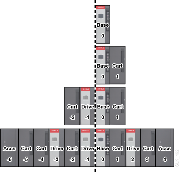
The Center Line of the Library and Module Numbers
Addressing uses the left edge of the Base Module (as viewed from the front of the library) as a reference point, called the center line. The figure below shows the location of the center line for various library configurations.
Module numbers starts with the Base as module zero (0) and increments positively to the right and negatively to the left.
Library Cell Addressing Scheme
Cell Addressing Overview
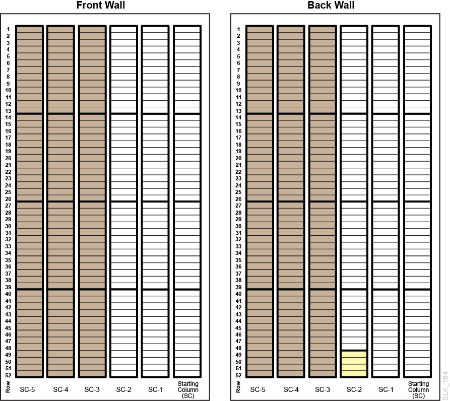
Cell addressing designates physical location using Library, Rail, Column, Side, Row (L, R,C,S,W). The GUI only uses (C, S, W) for the SL4000.
- Library
-
Always 1 for SL4000 libraries.
- Rail
-
Always 1 for SL4000 libraries.
- Column
-
Indicates the horizontal location of a storage cell or drive bay referenced from the center line:
-
Positive (+) value indicates right of center line
-
Negative (-) value indicates left of center line
-
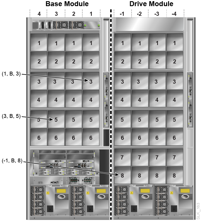
Zero (0) is never used for a column number. The first column to the right of the center line (viewed from the front of the library) is column 1. The first column to the left of the center line is column -1.
Base Module — Contains columns 1 to 6 for storage cells and 1 to 4 for drive cells.
Drive Module — Contains six columns for storage cells and four for drive bays. Column numbering for storage cells continues consecutively from the adjacent module. Column numbering for drive bays uses the storage cell columns that are closest to zero. For example, a Drive Module immediately to the right of the Base Module will contain storage cell columns 7 through 12 and drive columns 7 through 10. A Drive Module immediately to the left of the Base Module will contain storage cell columns -6 through -1 and drive columns -4 through -1.
Cartridge Module — Contains six columns for storage cells. Column numbering continues consecutively from the adjacent module.
Parking Module — Contains three columns for storage cells. The outer most three columns are inactive. Column numbering continues consecutively from the adjacent module.
Access Module — Contains three columns for storage cells. Column numbering continues from the adjacent module.
-
- Side
-
-
Back wall (drive side) = 1 (B in GUI)
-
Front wall (CAP side) = 2 (F in GUI)
-
- Row
-
The vertical location of a storage cell, consecutively numbered top down (1 to 52).
Cell Addressing of Tape Drive Bays
The library addressing distinguishes a drive bay by column and row. The side value is always 1 (shown as B in the GUI).
Cell Addressing of Rotational CAP Cell
- Column
-
The CAP column depends on the location of the module containing the CAP. The CAP column value corresponds to the fifth column from the left-side of the module. For example, module number 2 (second module to the right of the Base) will have storage columns 13 through 18 and the rotational CAP column will be 17. Module number -3 (third module to the left of the Base) will have storage cell columns -18 through -13 and the rotational CAP column will be -14.
- Side
-
Always 2 (shown as F in the GUI), since the CAPs are only located on the front of the module.
- Row
-
When addressing a specific cell: the row value is the cell in the CAP magazine (values 1 to 26).
- Example CAP Cell Address
-
For this example, the library has Cartridge Module, Drive Module, Base Module, and all modules have a CAP. The top cell of the Cartridge Module CAP would be (-8, F, 1).
SCSI Element Addressing
Note:
Changing the library configuration or partition configuration can cause the library to re-assign element IDs.The SCSI element address depends on the element type. Each library or partition uses a fixed starting address for each element type. Then, within each element type, the element addresses are sequential.
-
Storage Elements (storage cells)
-
Begins at 2000 in left-most module.
-
Numbered top to bottom, back to front, and left to right.
-
-
Import/Export Elements (CAPs)
-
Begins at 10 for the left-most rotational CAP in the library.
-
All rotational CAPs are numbered first (top to bottom and left to right), followed by the left Access Module CAP and then the right Access Module CAP (numbered top to bottom, back to front, and left to right).
-
-
Data Transfer Elements (drives and empty drive bays)
-
Begins at 1000 in the left-most Drive Module or Base and increments by one for every drive or empty drive bay.
-
Numbered top to bottom, left to right.
-
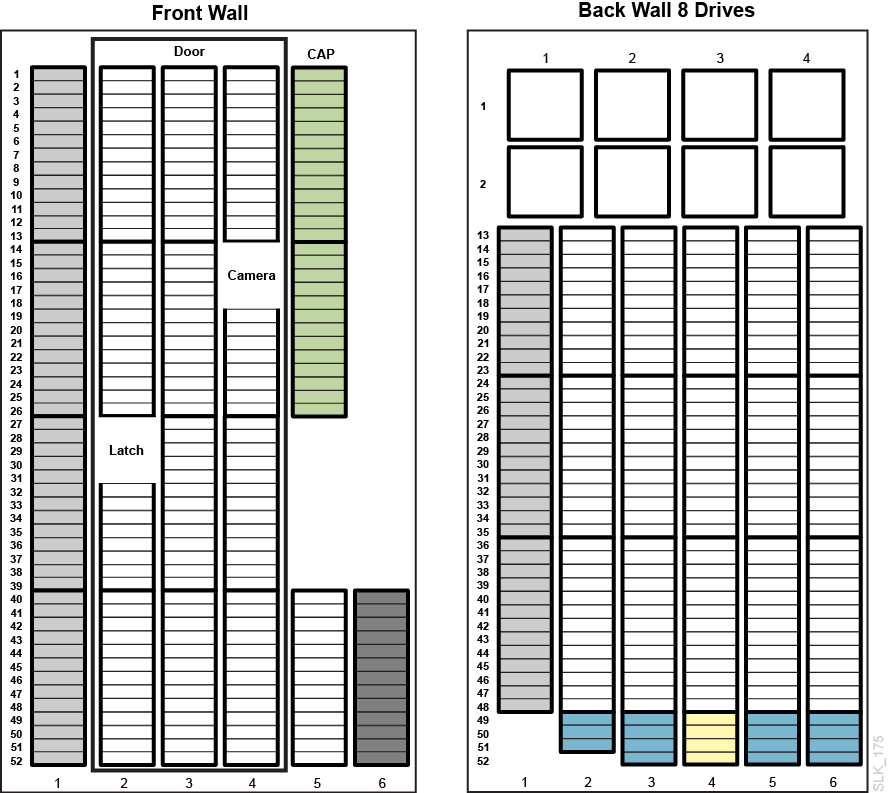
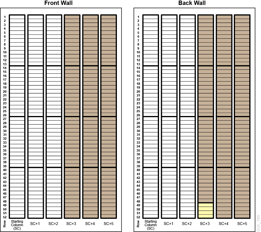
Cell Maps
-
Base Module front wall and back wall 8 drives (Figure B-2)
-
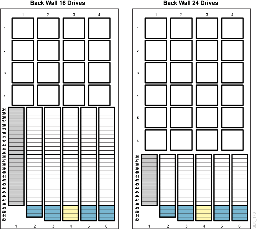
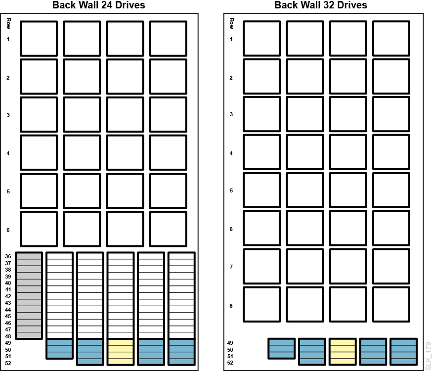
Base Module back wall 16 drives and 24 drives (Figure B-3)
-
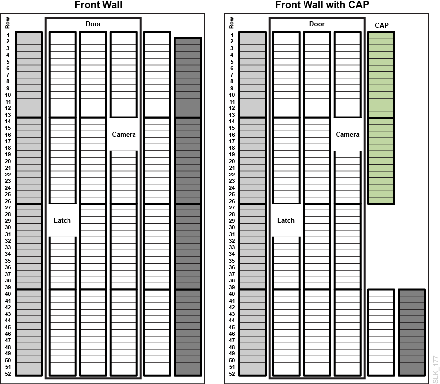
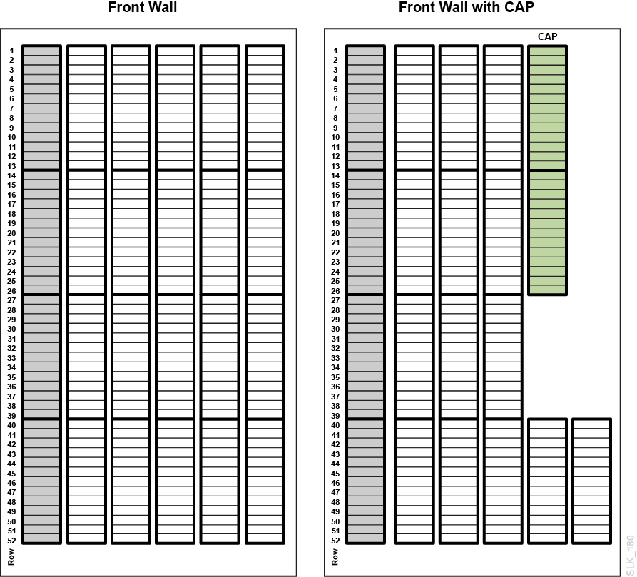
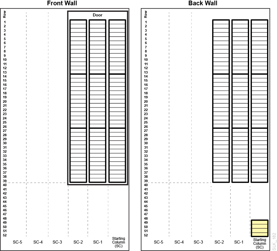
Drive Module front wall (Figure B-4)
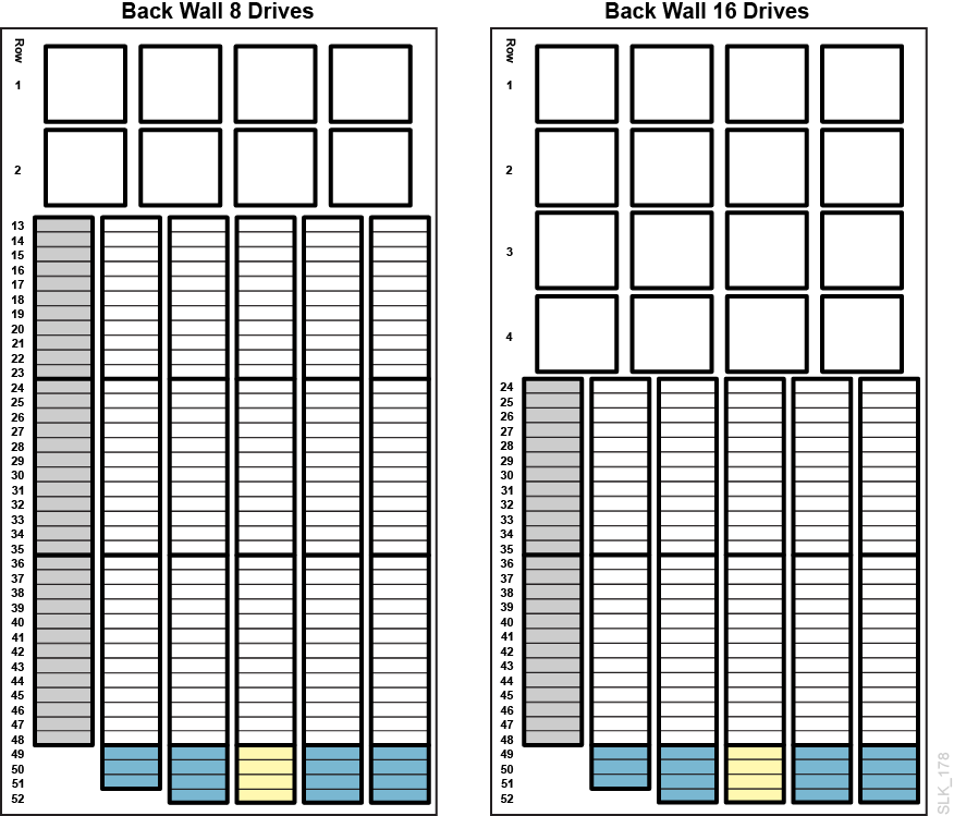
-
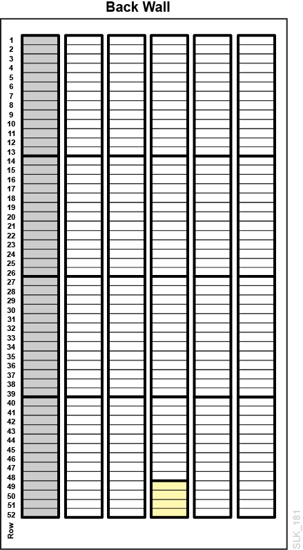
Drive Module back wall (Figure B-5 and Figure B-6)
-
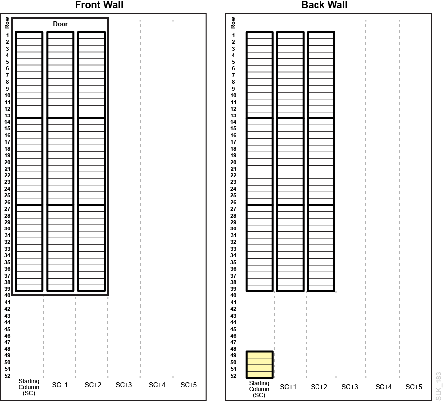
Cartridge Module front wall (Figure B-7)
-
Cartridge Module back wall (Figure B-8)
-
Left Parking Module (Figure B-9)
-
Right Parking Module (Figure B-10)
-
Left Access Module (Figure B-11)
-
Right Access Module (Figure B-12)
| Cell | Description |
|---|---|
| Normal data storage cell | |
| CAP cell | |
| Unavailable with no module to left | |
| Unavailable with no module to right | |
| Unavailable in a Parking Module | |
| Module identification block (see "Module Identification Block") | |
| System cell for cleaning and diagnostic tapes |