Creating a New Topology
Use the Topology page to create a new topology.
To create a new topology:
Click the Add New Topology button available on the upper-right corner of the Topology Definitions page.
In the Topology Information page, enter the topology name and the corresponding description.
Click the Add Node button to create a node. This opens the Add Node page.
Use the Add Node page to set the values for node attributes like Operating System, sizing parameter, disk to be attached, and the PeopleSoft component to be installed.
Add additional nodes as needed.
Click Save to save the details.
The following are the set of current validation rules for topology:
If there is a full tier node, then you:
Cannot have another full tier node.
Cannot have a middle tier node.
Cannot have a database node.
Cannot have a Database as a Service node.
If there is a mid-tier node, then you:
Cannot have a full tier node.
Must have either a Database as a Service node or a database (on Compute) node.
If there is a database node, then you:
Cannot have another database node.
Cannot have a Database as a Service node.
Cannot have a full tier node.
If there is a Database as a Service node, then you:
Cannot have another Database as a Service node.
Cannot have database node.
Cannot have a full tier node.
Apart from this, you may have a Windows Client Node in all the above mentioned cases and an optional Search Stack Node.
Use the Topology Information page (ECL_TOPO_COMP_FL) to create a new topology.
Navigation:
Click the Add New Topology button on the upper-right corner of the Topology Definitions page to access the Topology Information page. Click the Add Node button to add one or more nodes. The following sections include descriptions of various node definitions.
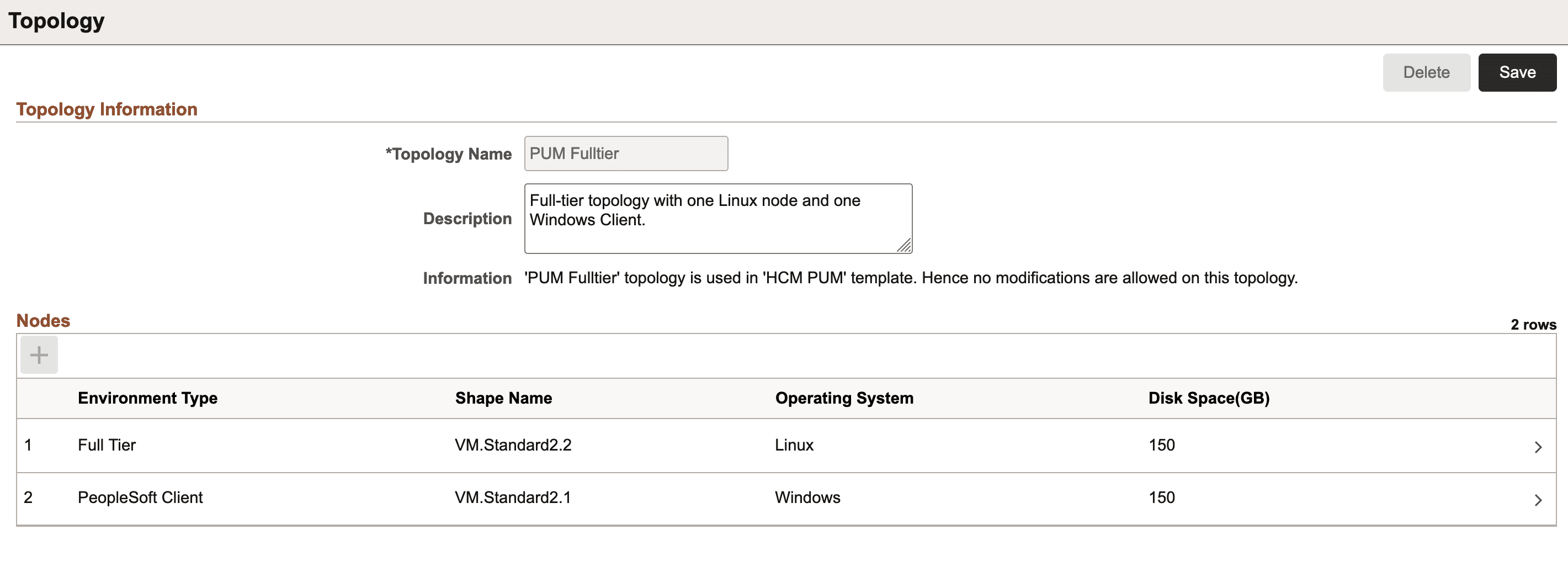
This example illustrates the fields and controls on the Topology Information page.
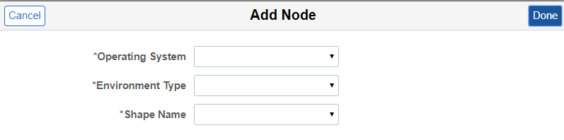
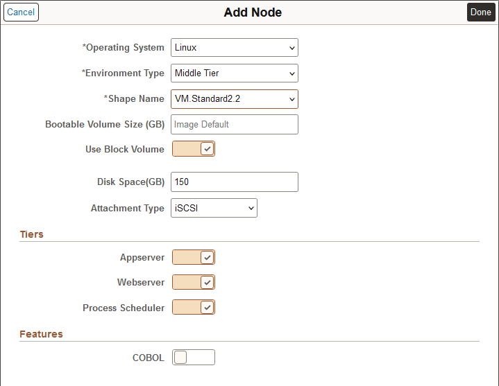
Use Add Node page to add nodes for creating a topology.
This example illustrates the fields and controls on the Add Node page. You can find definitions for the fields and controls later on this page.
|
Field or Control |
Description |
|---|---|
|
Operating System |
Select the operating system (Linux or Windows) used to create the topology. |
|
Environment Type |
Select the PeopleSoft software components to be deployed on the node. The following environment types are available for Linux operating system:
The following environment types are available for Windows operating system: Note: For applying PeopleTools patch to an environment, it is mandatory to have a PeopleSoft client or a Windows middle tier node defined.
|
|
Shape Name |
Select the required VM shape. For DB systems, VM shapes and Exadata are supported. Note: The Exadata DB System must already exist on OCI. When you select Exadata, the environment (shift) will create the databases within the Exadata DB system. For non-DB system nodes, the list of VM shapes depends on the custom Linux and Windows images that are specified in the "Infrastructure Settings" page. In OCI, whenever a user creates a custom Linux or Windows image, a set of shapes get associated with that image. CM shows that set of shapes, when the end user creates or modifies the nodes in a topology. Note: The list of shapes will not appear until you do a Refresh of OCI Metadata after configuring the Operating System images in the Settings page. Some shapes may not be available in new tenancies. |
|
Bootable Volume Size (GB) |
Enter the size in GB for the boot volume. The default is the size set by the image. If this option is not enabled, the default is set to 150 GB. |
|
Use Block Volume |
Enable this option to use a block volume in addition to the instance boot volume for the node. This option is enabled by default. Disable this option to use only the instance boot volume for the node. Note: This option is not available for DB Systems. For a definition of boot and block volume, see Overview of Block Volume in the Oracle Cloud Infrastructure documentation. |
|
Disk Space (GB) |
Select the amount of disk space attached to the VM instance. Note: Assume that if the lifted DPK is K size, then the disk size should be 2.5 times K. Note: For DB System, only a limited set of pre-defined disk sizes are supported. The allowed disk sizes are:
Note: For BM or Exadata DB system shapes, this field is not visible. |
|
Attachment Type |
Select iSCSI or Paravirtualization as the method to attach a block volume to the VM instance. Paravirtualized attachments simplify the process of configuring your block storage by removing the extra commands that are required before connecting to an iSCSI-attached volume. The trade-off is that IOPS performance for iSCSI attachments is greater than that for paravirtualized attachments. For information on these methods, see Volume Attachment Types in the Oracle Cloud Infrastructure documentation. |
Available shapes for Database Systems (DB Systems) are:
VM
Exadata
Note: Before performing an environment shift, you must modify the Lift and Shift - DBaaS topology with the required size and capacity of the database.
Database System Node on Exadata
When you select the shape name as Exadata, you are instructing Cloud Manager to create the environment (shift) with the databases on your existing Exadata DB System on OCI.
When you select Exadata for the DB Systems, disk space is not displayed.
Important! Exadata database is a RAC system which supports multiple nodes (VMs). You need to add the SSH public key for the Cloud Manager user on all nodes. See Adding SSH Keys to a VM Cluster in the Oracle Cloud Infrastructure documentation.
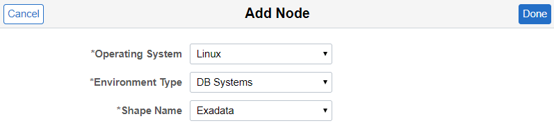
This example illustrates the fields and controls on the Add Node page for DB systems on Exadata.
When you add a middle tier node, the tiers section is displayed.
This example illustrates the fields and controls on the Add Node page for Middle Tier. You can find definitions for the fields and controls later on this page.
Select the tier or tiers for this node.
This table lists the supported combinations for the tiers:
|
Application Server |
Web Server (PIA) |
Process Scheduler |
|---|---|---|
|
Yes |
Yes |
Yes |
|
Yes |
No |
Yes |
|
Yes |
No |
No |
|
No |
Yes |
No |
|
No |
No |
Yes |
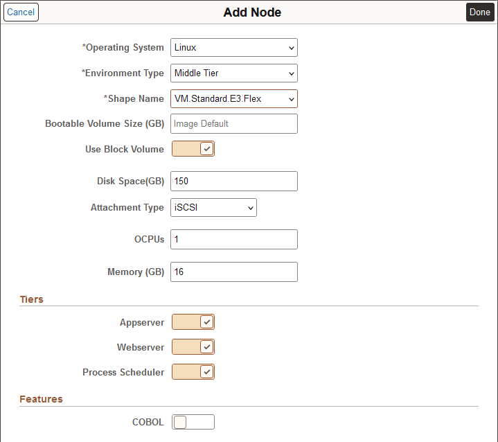
You can select one of the available Flex shapes for Linux Middle Tier and Full Tier nodes. A node with a Flex shape requires additional settings.
This example illustrates the fields and controls on the Add Node page for VM.Standard.E3.Flex shape. You can find definitions for the fields and controls later on this page.
|
Field or Control |
Description |
|---|---|
|
OCPUs |
Select from 1 to 64 OCPUs. |
|
Memory (GB) |
For each OCPU, you can select up to 64 GB of memory, with a maximum of 1024 GB total. The minimum amount of memory allowed is either 8 GB or a value matching the number of OCPUs, whichever is greater. |
COBOL can be enabled in the node only when environment type is Full Tier or Middle Tier with Process Scheduler enabled.
This example illustrates a middle tier node with Process Scheduler and COBOL enabled.
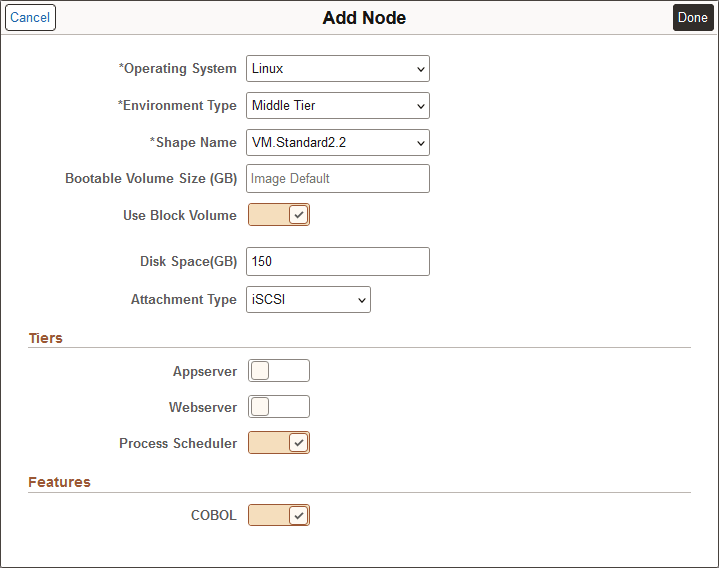
Note: Process Scheduler must be enabled in order to enable COBOL.
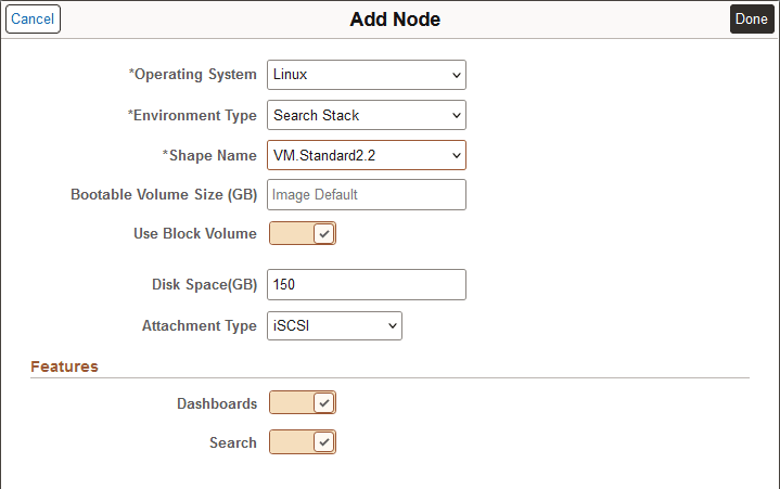
Note the following regarding the components for Search Stack nodes:
The node configuration of search component is automatically done by Cloud Manager.
You can select either OpenSearch or Elasticsearch as the search provider, based on the PeopleTools release.
Select Search to enable either OpenSearch or Elasticsearch, and Dashboards to enable either OpenSearch Dashboards or Kibana. The selection for the search provider is part of Template configuration.
See Configuring Search Stack General Settings
For information on how to deploy and configure OpenSearch refer to PeopleSoft Search and Insights Home Page on My Oracle Support (Doc ID 2205540.2) and PeopleTools: Search Technology.
In order to provision Kibana, you must select Elasticsearch.
In order to provision OpenSearch Dashboards, you must select OpenSearch.
For environments configured with OpenSearch, OpenSearch Dashboards will be automatically installed as part of the PeopleTools upgrade to 8.60.07.
OpenSearch and OpenSearch Dashboards are only available with PeopleTools 8.60.07 or later, in addition to Elasticsearch and Kibana. Support is also available for PeopleTools 8.59.21 patch or later. For more information on support, see the PeopleSoft Cloud Manager Home Page (My Oracle Support, Doc ID 2231255.2).
PeopleTools 8.61 supports only OpenSearch and OpenSearch Dashboards.
This example illustrates the fields and controls on the Add Node page for Search Stack.
Starting with Cloud Manager Update Image 10, you can create multiple Windows middle tier nodes. You can use either a custom Windows image or an OCI platform image. The image is selected on the Infrastructure Settings page.
Prerequisites:
Configure the Windows Image in Infrastructure Settings.
Subscribe to the Windows channel for your application.
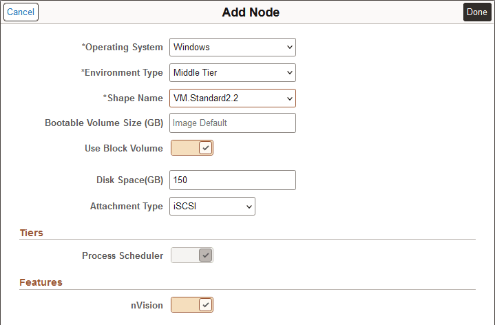
Use the Add Node page to create a new Windows node.
This example illustrates the fields and controls on the Add Node page with Windows Operating System selected. You can find definitions for the fields and controls later on this page.
|
Field or Control |
Description |
|---|---|
|
Operating System |
Select Windows. |
|
Environment Type |
Select Middle Tier. |
|
Shape Name |
Select the required VM shape. |
|
Bootable Volume Size (GB) |
Enter the size in GB for the boot volume. The default is the size set by the image. If this option is not enabled, the default is set to 150 GB. |
|
Use Block Volume |
Enable this option to use a block volume in addition to the instance boot volume for the node. This option is enabled by default. Disable this option to use only the instance boot volume for the node. For a definition of boot and block volume, see Overview of Block Volume in the Oracle Cloud Infrastructure documentation. |
|
Disk Space (GB) |
Select the amount of disk space attached to the VM. |
|
Attachment Type |
Select iSCSI or Paravirtualization. |
|
Tiers |
Only Process Scheduler domain is supported for Windows middle tier Node. Windows Process Scheduler is required for running nVision reports. |
|
Features |
The nVision feature can be set either on or off. |
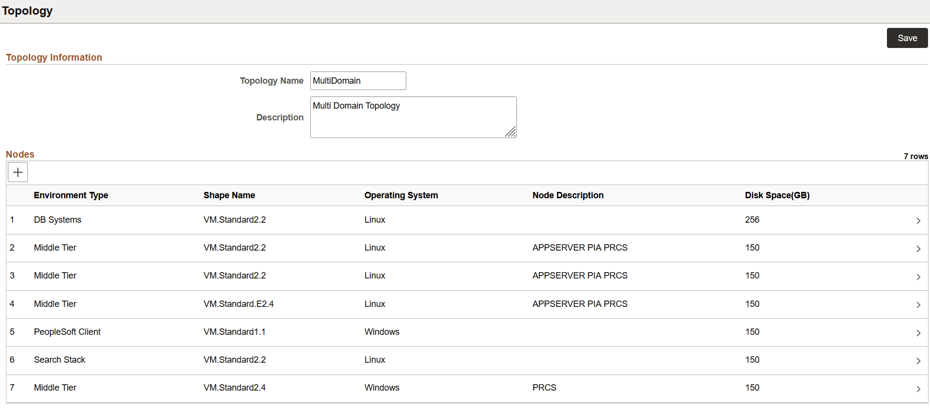
Cloud Manager Update Image 8 and above supports both horizontal and vertical elasticity by allowing multi node and multi domain configuration for the PeopleSoft environment.
Cloud Manager supports multiple middle tier and PIA domains on single node as well on multiple nodes. It also provides an option to enable Integration Broker in one application domain in an environment. This Domain Configuration feature extends the existing provisioning environment feature in Cloud Manager.
See Configuring AppServer Tier Domain Settings.
This example illustrates the fields and controls on the Topology page for a topology with multiple middle tiers.