1.3 GeoRaster Data Model
Raster data can have some or all of the following elements.
-
Cells or pixels
-
Spatial domain (footprint)
-
Spatial, temporal, and band reference information
-
Cell attributes
-
Metadata
-
Processing data and map support data
GeoRaster defines a generic raster data model that is component-based, logically layered, and multidimensional. The core data in a raster is a multidimensional array or matrix of raster cells. Each cell is one element of the matrix, and its value is called the cell value, which is sampled at the center of the cell. If the GeoRaster object represents an image, a cell can also be called a pixel, which has only one value. (In GeoRaster, the terms cell and pixel are interchangeable.) The matrix has a number of dimensions, a cell depth, and a size for each dimension. The cell depth is the data size of the value of each cell. The cell depth defines the range of all cell values, and it applies to each single cell, not to an array of cells. This core raster data set can be blocked for optimal storage and retrieval.
The data model has a logically layered structure. The core data consists of one or more logical layers. For example, for multichannel remote sensing imagery, the layers are used to model the channels of the imagery. (Bands and layers are explained in Bands_ Layers_ and Metadata.) In the current release, each layer is a two-dimensional matrix of cells that consists of the row dimension and the column dimension.
GeoRaster data has metadata and attributes, and each layer of the GeoRaster data can have its own metadata and attributes. In the GeoRaster data model, all data other than the core cell matrix is the GeoRaster metadata. The GeoRaster metadata is further divided into different components (and is thus called component-based), which contain the following kinds of information:
-
Object information
-
Raster information
-
Spatial reference system information
-
Date and time (temporal reference system) information
-
Band reference system information
-
Layer information for each layer
Based on this data model, GeoRaster objects are described by the GeoRaster metadata XML schema (described in GeoRaster Metadata XML Schema), which is used to organize the metadata. Some schema components and subcomponents are required and others are optional. You must understand this XML schema if you develop GeoRaster loaders, exporters, or other applications. Some restrictions on the metadata exist for the current release, and these are described in the Usage Notes for the SDO_GEOR.validateGeoRaster function (documented in SDO_GEOR Package Reference), which checks the validity of the metadata for a GeoRaster object.
The GeoRaster object data types, described in GeoRaster Data Types and Related Structures, are based on the GeoRaster data model.
In this data model, two different types of coordinates need to be considered: the coordinates of each pixel (cell) in the raster matrix and the coordinates on the Earth that they represent. Consequently, two types of coordinate systems or spaces are defined: the cell coordinate system and the model coordinate system.
The cell coordinate system (also called the raster space) is used to describe cells in the raster matrix and their spacing, and its dimensions are (in this order) row, column, and band. The model coordinate system (also called the ground coordinate system or the model space) is used to describe points on the Earth or any other coordinate system associated with an Oracle SRID value. The spatial dimensions of the model coordinate system are (in this order) X and Y, corresponding to the column and row dimensions, respectively, in the cell coordinate system. The logical layers correspond to the band dimension in the cell space.
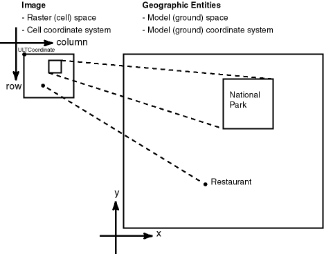
Figure 1-1 shows the relationship between a raster image and its associated geographical (spatial) extent, and between parts of the image and their associated geographical entities.
In Figure 1-1:
-
In the objects on the left, the medium-size rectangle represents a raster image, and within it are a rectangular area showing a national park and a point identifying the location of a specific restaurant. Each pixel in the image can be identified by its coordinates in a cell coordinate system (the coordinate system associated with the raster image). The upper-left corner of the medium-size rectangle has the coordinate values associated with the
ULTCoordinatevalue of the cell space for the GeoRaster object. -
In the objects on the right, the large rectangle represents the geographical area (in the model, or ground, space) that is shown in the raster image, and within it are spatial geometries for the national park and the specific restaurant. Each entire geographical area and geometries within it can be identified using coordinates in its model (or, ground) coordinate system, such as WGS 84 for longitude/latitude data.
For two-dimensional single-layer GeoRaster data, the cell coordinate system has a row dimension pointing downward and a column dimension pointing to the right, as shown in Figure 1-1. The origin of the cell space is always (0,0). The spacing is 1 cell or 1 pixel, and in most cases the cell coordinates are identified by integer row and column numbers. For a multiband image, the axis along bands is called the band dimension. For a time series multilayer image (where each layer has a different date or timestamp), the axis along layers is called the temporal dimension. Three-dimensional GeoRaster data includes the vertical dimension, which is vertical to both the row and column dimensions.
Note:
Only row, column, and band dimensions in the cell coordinate system are currently supported. The row and column dimensions are used to model two-dimensional spatial coordinates. The band dimension can be used to model multichannel remote sensing imagery or photographs and any other types of layers, such as temporal layers and multiple-grid themes.When the raster data is treated and processed as an array of numbers, integer addressing using row and column numbers is sufficient in most applications. However, the raster data array is generally a discretized representation of a continuous space, and so a one-to-one mapping of coordinates between the cell space and the model space is required, regardless of whether the value of a cell represents a collective value of an area or a single value of a point.
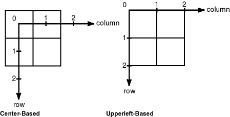
In other words, sub-cell (sub-pixel) addressing in the cell space is necessary. To support sub-cell addressing, GeoRaster defines two types of cell coordinate systems, depending on where the origin (0,0) of cells is defined. Figure 1-2, where each square represents one cell, shows the two types of cell coordinate systems: center-based and upperleft-based.
Figure 1-2 Two Types of Cell Coordinate Systems

Description of "Figure 1-2 Two Types of Cell Coordinate Systems"
The default cell coordinate system has its origin at the center of a cell, and is called the center-based cell coordinate system. The other cell coordinate system has its origin at the upper-left corner of a cell, and is called the upperleft-based cell coordinate system. In both systems, the cells are squares with equal size and the unit is 1 cell. Assuming that I and J are integers, and x and y are floating numbers:
-
In center-based cell space, coordinate (x, y) is mapped to (I,J) as long as I-0.5 <= x < I+0.5 and J-0.5 <= y < J+0.5.
-
In upperleft-based cell space, coordinate (x, y) is mapped to cell (I,J) as long as I <= x < I+1.0 and J <= y < J+1.0.
For example, sub-cell coordinate (0.3, 0.3) has the same integer cell coordinate (0,0) in both coordinate systems, while (0.3,0.6) means (0,1) in center-based cell space but means (0,0) in upperleft-based cell space. This two types of cell coordinate systems are defined by the modelCoordinateLocation element in the spatialReferenceInfo metadata; otherwise, the default type is center-based. GeoRaster supports both cell coordinate systems, and effective with Oracle Database 11g, sub-cell addresses are supported in the GeoRaster PL/SQL API. (Sub-cell addresses were internally supported in previous releases.)
In GeoRaster, while the origin of the cell space is always at (0,0), the upper-left corner cell of the raster data itself can have a different coordinate in its cell space from the coordinate of the origin of the cell space. In other words, the integer (row, column) coordinate of the upper-left corner cell is not necessarily (0,0). The upper-left corner is called the ULTCoordinate, and its value is registered in the metadata. It basically defines the relative location of the data in the cell space. If there is a band dimension, the ULTCoordinate value is always (row,column,0). The coordinate of each cell is relative to the origin of the cell space, not to the ULTCoordinate value. The origin of the cell coordinate system might not be exactly at the ULTCoordinate value.
The model coordinate system consists of spatial dimensions, and other dimensions if there are any. The spatial dimensions are called the x, y, and z dimensions, and values in these dimensions can be associated with a geodetic, projected, or local coordinate system. Other dimensions include spectral and temporal dimensions (called the s dimension and t dimension, respectively). GeoRaster SRS currently supports two spatial dimensions (X,Y) and three spatial dimensions (X, Y, Z) in the model coordinate system. (For information about coordinate systems, including the different types of coordinate systems, see Oracle Spatial Developer's Guide.)
The GeoRaster model coordinate system is defined by an Oracle Spatial SRID. The model coordinates have the same unit as that of the specified SRID and should be in the value range defined by the model coordinate system. For example, if the GeoRaster object is georeferenced to a geodetic coordinate system such as 4326 (EPSG WGS84), the unit of the model coordinates derived from the spatial reference system (SRS) must be decimal degrees, and values should be in the ranges of -180.0 to +180.0 for longitude and -90.0 to +90.0 for latitude.
The relationships between cell coordinates and model coordinates are modeled by GeoRaster reference systems (mapping schemes). The following GeoRaster reference systems are defined:
-
Spatial reference system, also called GeoRaster SRS, which maps cell coordinates (row,column,vertical) to model coordinates (X,Y,Z). Using the spatial reference system with GeoRaster data is referred to as georeferencing the data. (Georeferencing is discussed in Georeferencing.)
-
Temporal reference system, also called GeoRaster TRS, which maps cell coordinates (temporal) to model coordinates (T).
-
Band reference system, also called GeoRaster BRS, which maps cell coordinates (band) to model coordinates (S, for Spectral).
Each of these reference systems is currently defined, at least partially, in the GeoRaster XML schema. However, for the current release, only the spatial reference system is supported. This means that only the relationship between (row,column) and (X,Y) or (X, Y, Z) coordinates can be mapped. If the model coordinate system is geodetic, (X,Y) means (longitude,latitude). The temporal and band reference systems can be used, however, to store useful temporal and spectral information, such as the spectral resolution and when the raster data was collected.
Other metadata is stored in the <layerInfo> element in the GeoRaster XML metadata, as explained in Bands_ Layers_ and Metadata.
Parent topic: GeoRaster Overview and Concepts
