This section describes the preparation steps to perform before installing an additional compute node as part of your Oracle Private Cloud Appliance.
When adding expansion nodes, always populate the compute rack units starting from the bottom most open slot, and work your way up. If you do not populate the rack units in the right order, the controller software may no longer report the correct status of the rack components.
Electronic equipment is susceptible to damage by static electricity. To prevent electrostatic discharge (ESD) when you install or service the server:
Use a grounded antistatic wrist strap, foot strap, or equivalent safety equipment.
Place components on an antistatic surface, such as an antistatic discharge mat or an antistatic bag.
Wear an antistatic grounding wrist strap connected to a metal surface on the chassis when you work on system components.
Equipment damage: Electrostatic damage can permanently disable the system or require repair by authorized service technicians.
Before installing the server, read the safety information in the Oracle Server X8-2 Safety and Compliance Guide, as well as the Important Safety Information for Oracle's Hardware Systems.
Perform the following procedure to unpack the server upgrade kit.
Inspect the shipping cartons for evidence of physical damage. If a shipping carton appears damaged, request that the carrier agent be present when the carton is opened. Keep all contents and packing material for the agent inspection.
Remove the packaging from the Oracle Private Cloud Appliance Expansion Node upgrade kit.
Verify that all items are included. The upgrade kit should contain the following:
Oracle Server
Cable management arm assembly with installation instructions
Rackmount kit including rack rails, mounting brackets, screws and Rackmounting Template
Getting Started Guide
Legal and safety documents
NoteCables are not included in the server upgrade kit. Oracle Private Cloud Appliance comes with pre-installed and labeled cables for all rack units. These should not be unplugged or removed from the rack.
Perform the following procedure to prepare the rack.
To reduce the risk of personal injury, stabilize the rack cabinet and extend all anti-tilt devices before performing this procedure.
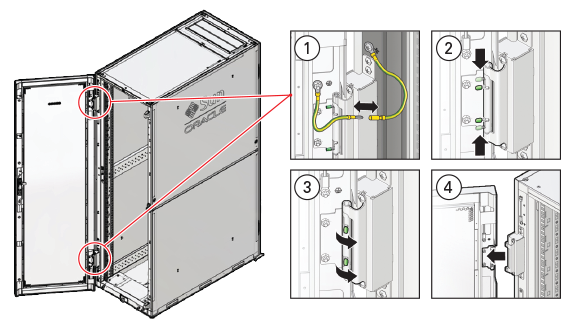
Remove the Oracle Private Cloud Appliance front and rear rack doors, as follows:
Unlock and open the front and rear rack doors.
Detach the top and bottom grounding straps by separating the banana jacks (1).
Unlatch the bottom hinge, then the top hinge.
Pinch the two studs on the hinge towards the center of the hinge (2).
Rotate the studs away from the door (3) so that they stay in place and the hinge remains unlatched.
Lift the door away from the cabinet (4).
Repeat these steps for the two rear doors.
These steps are illustrated in Figure 6.1.
CautionThe doors are heavy. Have one person hold the door in place while the other operates the hinge latching mechanism. Execute the steps carefully and in the correct order, to avoid damage to the hinges.
Table 6.2 Figure Legend
Item
Description
1
Detaching the grounding cables.
2
Pinching the hinge studs.
3
Rotating the studs away from the door.
4
Lifting the door away from the cabinet.
Remove the filler panel(s) where the upgrade server will be installed.
The filler panels have snap-in attachments. No screwdriver is required to remove them.
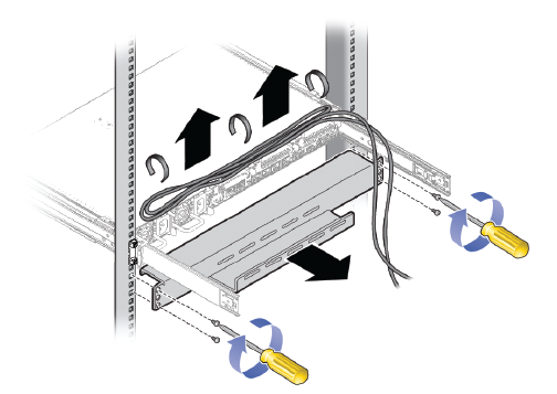
Remove the cable tray that holds the pre-installed cables in place at the rear side of the rack. See Figure 6.2
Detach the pre-installed cables from the cable tray on the rack unit for the new expansion node.
Use a No. 2 Phillips screwdriver to remove the M6 screws from the cable tray.
Remove the cable tray from the rack. Save cable tray and screws for future use.