A E1 Interface

Appendix A, E1 Interface, contains general information about the E1 interface and how to provision it.

A.1 Introduction

The E1 interface terminates or distributes E1 facility signals for the purpose of processing the SS7 signaling links carried by the E1 carrier. The E1 interface can be either a an E1/T1 MIM card, an E5-E1T1-B card, or SLIC card as shown in Figure A-1, and Figure A-2. The E1/T1 MIM or E5-E1T1-B card can also be used as a T1 interface. This appendix describes how an E1 interface is configured using either the the E1/T1 MIM card or E5-E1T1-B card. The T1 interface configuration is described in T1 Interface.

Note:

The procedures in this appendix are used only to configure E1 signaling links on the E1/T1MIM card or E5-E1T1-B card. To configure an E1 high-speed signaling link (on the LIME1ATM card), go to the Adding an ATM High-Speed Signaling Link procedure.

The E1/T1 MIM card contains up to eight signaling links and allows the EAGLE to contain more than 500 signaling links.

Figure A-1 E1/T1 MIM Block Diagram


img/e1-t1_mim_block_diagram.jpg

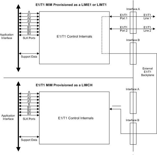
Figure A-2 E5-E1T1-B Block Diagram


img/hcmim_e5-e1t1_t1_block_diagram.jpg

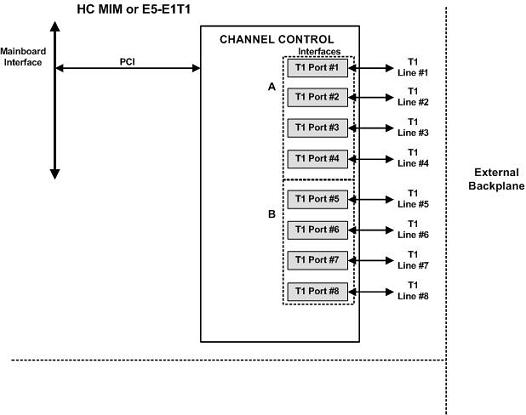
Table A-1 provides an overview of the functions of the E1 card and the channel card.

Table A-1 Functional Overview of the E1 and Channel Card

Card Function
E1
  • Connectivity of both E1 interfaces to a 120 Ohm or 75 Ohm E1 interface. An external adapter is required for the 75 Ohm interface.
  • Processing up to a total of eight (only two if an E1T1 MIM is being used) time slots from the E1 interfaces
  • Interface E1 port 1 through an external backplane to channel cards for processing of additional time slots
Channel
  • Processing up to eight (only two if an E1T1 MIM configured as a channel card is being used) time slots from the E1 interface
  • Interface through an external backplane to an E1 card to process up to eight (only two if an E1T1 MIM configured as a channel card is being used) time slots

Configured as an E1 Card

Configured as an E1 card, two separate and independent E1 inputs can be terminated on an E1 card. If an E1/T1 MIM is being used, one to eight bi-directional channels are extracted from the E1 inputs and processed as SS7 signaling links. Implemented as E1 Link Interface Modules, up to thirty two separate and independent E1 inputs can be terminated in an Extension Shelf. The E1 card can support signaling links transmitting at either 56 kbps or 64 kbps.

Configured as a Channel Card

In an Extension shelf equipped with an E1 cabling backplane, an E1 card terminates one or two E1 inputs and connects the E1 port 1 input to one of eight available busses on the E1 cabling backplane. Channel cards also connected to the E1 cabling backplane are able to extract any eight signaling channels from the same E1 port 1 input. In this manner, up to 31 E1 channels can be used for signaling - the 32nd channel is reserved for E1 synchronization. The E1 card can support signaling links transmitting at either 56 kbps or 64 kbps.

Note:

An E5-E1T1-B card cannot be used as a channel card.

High Capacity Multi-Channel Interface Module (HC-MIM) and Eagle 5 - E1 T1 Interface (E5-E1T1)

The EAGLE 5 - E1 T1-B Interface (E5-E1T1-B) provides access to eight E1 ports residing on backplane connectors A and B. Each data stream consists of 31 E1 DS0 signaling links assigned in a time-division multiplex manner. Each channel occupies a unique timeslot in the data stream and can be selected as a local signaling link on the interface card. A maximum of 64 E1 signaling links can be assigned to an appropriate card. A maximum of 32 E1 signaling links can be assigned to an E5-E1T1-B card.

To support the processing of signaling channels that are intermixed on trunks with voice or data channels, the E5-E1T1-B card allows E1 ports to be channel bridged. This allows better utilization of E1 bandwidth without dedicating entire trunks to signaling.

Figure A-3 Channel Bridging

img/channel_bridging_350.jpg

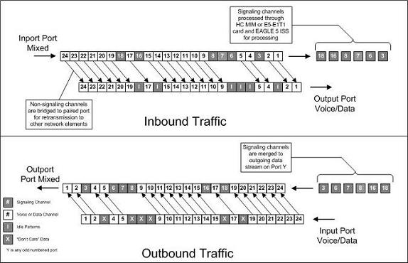
Channel bridging is implemented by pairing odd and even E1 ports. The E1 port selected for channel bridging is the odd numbered port (1, 3, 5, 7). When the E1 port is selected for channel bridging, it is paired with its adjacent even numbered port (2, 4, 6, 8) as shown in Table A-2.

Table A-2 Channel Bridging E1 Port Pairing

Odd Numbered E1 Port (Bridging Master) Even Numbered E1 Port Bridged to the Odd Numbered E1 Port (Bridging Slave)
1 2
3 4
5 6
7 8

By pairing E1 ports, the adjacent even numbered E1 port could be used to allow data received on the bridging master (odd) E1 port to reach downstream network elements. This interface is a bi-directional interface so data is also able to enter the bridging slave (even) E1 port and leave the EAGLE through the bridging master (odd) E1 port. There is a 1 to 1 correspondence between the timeslots on the bridging master and slave E1 ports.

In order to use channel bridging without facility errors, both E1 ports (bridging master and slave) must be synchronous (timed off the same clock source). This may be accomplished in one of the following ways:

  • The bridging master E1 port and the bridging slave E1 port use timing recovered from each other (using the e1tsel=recovered parameter with either the ent-e1 or chg-e1 command). When provisioning channel bridged E1 port, only the bridging master E1 port is provisioned with the ent-e1 or chg-e1 command. The bridging slave E1 port is automatically provisioned with the same attributes as the bridging master E1 port.
  • Both the bridging master and slave E1 ports are using an external clock source (using the e1tsel=external parameter when provisioning the channel bridged E1 port with either the ent-e1 or chg-e1 command).

Any other methods used for timing could cause problems on the E1 trunk and are not supported.

Idle patterns on the shadow channels, that is, the timeslots located on the bridging slave E1 port that have been not been dropped from the bridging master E1 port, are provided by the EAGLE. All other idle timeslots that are not dropped by the EAGLE must contain an idle pattern provided by the remote network elements connected to both E1 ports (bridging master and slave). Without these patterns on the idle timeslots, instability of the E1 signaling link may occur.

Provisioning of signaling links on the bridging slave E1 port is not allowed while the bridging master E1 port is channel bridged.

A.2 Determining the Configuration

External Interface Descriptions

The E1 Interface Backplane provides a method for extending individual E1 channels from the E1-configured cards to any channel-configured cards in use. Note the following issues regarding the E1 backplane:

  • Only one E1-configured card may be plugged into each bus on the backplane.

  • When installing non-E1 cards on the shelf equipped with the E1 interface backplane, ensure that none of the slots to be used are cabled to the E1 interface backplane. If a non-E1 card is installed in a slot that is connected to the E1 backplane, all E1 cards on that bus may fail.

  • Only one E1 card may be connected (via the B port) to each bus of the E1 cabling backplane, and all SS7 links derived from any particular E1 must be processed on the same shelf on which the incoming E1 is terminated.

  • Due to cable congestion, Oracle does not recommend use of the E1 cabling backplane on the control shelf.

  • If the control shelf is used, a maximum of 20 E1 interfaces can be utilized in the control shelf.

The E1 backplane is impedance-controlled for 120 Ohms and is designed for use with RS-485 transmission characteristics.

Descriptions of the T1 hardware and the procedures for installing the T1 hardware are contained in Hardware Reference and Installation Guide.

Possible Configurations

The E1 backplane was designed to allow the maximum number of possible customer setups. It allows the customer to choose between several levels of diversity and convenience. Configurations depend on the number of cards configured as E1 cards versus the number of cards configured as channel cards. The level of diversity required by the customer also affects the configuration requirements. Note that all signals labelled “E1 input” may be one or two E1 ports depending on the cable used.

Support of Two E1 Ports

The E1 card will support two E1 ports, which are independently configurable. On an E1 card, E1 port 1 will support channel cards. The second port of that E1 card will only support up to a maximum of eight time slots and will not support channel cards.

Clocking Options

Each E1 interface must independently operate in one of two clocking modes. When configured as a channel card, an E1 card is required for the channel card’s clocking source.

  • Slave Timing - The default receive clock on the E1 card will be used as the source of the transmit clock.

  • Master Timing - The transmit clock of the E1 card will originate on this board. The oscillator on the board provides the clock source. Note the oscillator is less accurate than the network clock.

The Master Timing feature allows an E1 signaling link to take its high-speed clock reference directly from an external high-speed master clock source.

Support of E1 Framing Options

The E1 interfaces will independently support the following E1 framing options. Selection of these options will be made by the crc4 and cas parameters of either the ent-e1 or chg-e1 commands.

  • Clear Channel Signaling (CCS)

  • Channel Associated Signaling (CAS)

  • Cyclic Redundancy Check (CRC4)

The following provide for zero bit suppression: HDB3 (High Density Bipolar encoding of order 3).

On any given E1 card, CCS and CAS are mutually exclusive and cannot be used together. However, CRC4 may be added to either CCS or CAS.

LIM-E1 Card to Channel Card Interface

Whether the E1/channel card is operating as an E1 card or a channel card, the card will map any eight channels from the E1 interfaces to an HDLC controller (ports A, B, A1, B1, A2, B2, A3, B3 for the E1/T1 MIM card). These channels could be dropped either both from E1 port 1 or one from E1 port 1 and the other from E1 port 2. When the E1/channel card is configured as an E1 card, it will support the external E1 cabling backplane interface from E1 port 1 (E1 port 2 will not have this capability) to additional E1/channel cards, within the same shelf, configured as channel cards. Idle time slots not assigned to an E1 card or a channel card will be filled with a one’s pattern.

Channel Support

The E1/channel card will independently support either 56 kbps or 64 kbps on any channel.

Configuring the Signaling Links

The main consideration for the provisioning of E1s is to determine the number of E1s existing in the network and the equipment needed for grooming into the EAGLE. To utilize the flexibility of the E1 interface feature, you may want to determine the minimum number of E1 cards needed to process the total number of SS7 links and then consider diversity for reliability reasons.

Use the following points as guidelines when considering diversity for E1:

  • If possible, no two E1s containing links from a common link set should be on the same E1/dual port channel card.

  • If possible, no two E1s containing links from a common link set should be on adjacent E1/dual port channel cards where they are powered from the same fuse position.

  • If possible, no two E1s containing links from a common link set should be terminated on the same shelf because of the shelf clock cabling, and is only an issue if using master clocking sync to the network

  • If possible, no two links in a link set should arrive at the EAGLE on the same E1.

  • If possible, for link sets containing more than two links, you should minimize the number of links in that link set on any given E1.

As an example, consider a network to be groomed into the EAGLE consisting of 30 E1s with a total number of 100 links where the largest link set size is 8. The most efficient way to provision the EAGLE would be to have four extension shelves equipped with the E1 cabling backplane, one E1 card, and 12 channel cards per shelf. Utilizing one B bus on each shelf, 25 signaling links would be terminated on each shelf for a total of 100. This is also the minimum number of E1 cards required for this example.

With the same example but using the third and fifth bullets above as a consideration, the EAGLE would be provisioned with eight extension shelves equipped with the E1 cabling backplane. Four of the shelves would be equipped with one E1 card and six channel cards, and the other four shelves would be equipped with one E1 card and five channel cards. Since the largest link set size is eight, a total of eight E1 cards is required. Utilizing one B bus on each shelf, 13 signaling links would be terminated on each shelf with six channel cards, and 12 signaling links would be terminated on each shelf with five channel cards.

Note:

When retrieving link information from the database, the links for an E1 or channel card is not displayed until after the card is allowed.

E1 Configuration Form

Use the form provided below to record your E1 configuration. An example of the required input is shown in italics under each column heading.

Table A-3 E1 Signaling Link Configuration Form

Card Location and Port (1201 A) Timeslot (1) E1 Number (1) E1 Card Location (1201) Adjacent Point Code (4001) Linkset ( ST1ME ) SLC (1)


A.3 E1 Interface Configuration Procedures

This appendix contains these procedures because they contain information specific to the E1 Interface:

Procedures for configuring the linksets and routes, for removing SS7 signaling links (which includes E1 signaling links), and for configuring the HC MIM temperature alarms are contained in SS7 Configuration interface, therefore, are not included in this appendix.

The procedures contained in this appendix use a variety of commands. If more information on these commands is needed, go to Commands User's Guide to find the required information.

A.4 Adding a LIM-E1 Card

The LIM-El card is provisioned as either an E1 card or a channel card in the database using the ent-card command. The card being provisioned in the database can be one of these cards shown in Table A-4.

Table A-4 E1 Card Part Numbers

Card Type Part Number

E1/T1MIM

870-2198-XX

E5-E1T1

870-1873-XX

The ent-card command uses these parameters.

:loc – The location of the card being added to the database.

Note:

The HC-MIM can be inserted only in a odd-numbered card location. The HC-MIM will not power up if it is inserted in an even-numbered card location. All the E1 backplane cabling should be removed from the B connector for the slot that the HC-MIM will occupy.

The HC-MIM occupies two card locations, so the even numbered card location adjacent to the odd numbered slot where the HC-MIM has been inserted must be empty, as shown in Table A-5. The HC-MIM is connected to the network through the odd numbered card slot connector.

Table A-5 HC-MIM Card Locations

Location of the HC-MIM Empty Card Location Location of the HC-MIM Empty Card Location

Slot 01

Slot 02

Slot 11

Slot 12

Slot 03

Slot 04

Slot 13

Slot 14

Slot 05

Slot 06

Slot 15

Slot 16

Slot 07

Slot 08

Slot 17

Slot 18

The E1, E1/T1 MIM and E5-E1T1 cards occupy one card location. These cards can be placed in any card location except for even numbered card locations whose adjacent odd numbered card location is occupied by a card that occupies two card locations.

:type – The type of card being added to the database. For this procedure, the value of this parameter is lime1 (E1 card) or limch (channel card).

Note:

The HC-MIM and E5-E1T1 card cannot be provisioned as a channel card.

:appl – The application software that is assigned to the card. For this procedure, the value of this parameter is either ccs7itu or ss7ansi.

The shelf to which the card is to be added must already be in the database. This can be verified with the rtrv-shlf command. If the shelf is not in the database, see the Adding a Shelf procedure in Database Administration - System Management User's Guide.

The examples in this procedure are used to add the LIM-E1 cards in card locations 1201, 1202, 1203, 1204, 1211, and 1212 to the database.

  1. Display the cards in the EAGLE using the rtrv-card command.
    
    rlghncxa03w 09-05-28 09:12:36 GMT EAGLE5 41.0.0
    CARD   TYPE      APPL     LSET NAME   LINK SLC LSET NAME   LINK SLC
    1102   TSM       GLS       
    1113   GSPM      OAM
    1114   TDM-A
    1115   GSPM      OAM
    1116   TDM-B
    1117   MDAL
    

    The cards should be distributed throughout the EAGLE for proper power distribution. Refer to Installation Guide for the shelf power distribution.

  2. Verify that the correct hardware has been installed on the EAGLE to support the E1 card as shown in Installation Guide.
  3. Physically verify that the E1 card has been installed into the card location that will be specified in step 6.

    If the E1 card is an HC-MIM, make sure the HC-MIM is installed according to the card location requirements shown in Table A-5. If a card is installed and provisioned in the even numbered card location adjacent to the desired odd numbered card, either choose another card location to install and provision the HC-MIM, or remove the card in the even-numbered card location by performing the appropriate procedure shown in Table A-6 .

    Note:

    Channel cards must be installed in the same shelf as the E1 card that is servicing the timeslots on those channel cards.

    Table A-6 Card Removal Procedures

    Card Application Procedure

    SS7ANSI, ATMANSI, CCS7ITU, ATMITU

    “Removing an SS7 LIM” in Chapter 4, “System Configuration Procedures” in Database Administration - System Management User's Guide

    “Removing a LIM-E1Card

    “Removing a LIM-T1Card

    VSCCP

    Removing a Service Module in Chapter 2 in Database Administration - GTT User's Guide

    GLS

    Removing a GLS Card in Chapter 2, Gateway Screening (GWS) Overview, in Database Administration - GWS User's Guide

    IPLIM, IPLIMI, SS7IPGW, IPGWI

    "Removing an IPLIMx Card" or Removing an IPGWx Card" in Database Administration - IP7 User's Guide

    IPSG "Removing an IPSG Card" in Database Administration - IP7 User's Guide

    EROUTE

    “Removing an STC Card” in Database Administration - Features User's Guide

    MCP

    “Removing an MCPM” in Chapter 4, “System Configuration Procedures” in Database Administration - System Management User's Guide

    IPS

    “Removing an IPSM” in Chapter 4, “System Configuration Procedures” in Database Administration - System Management User's Guide

    Note:

    If the E1 card being added in this procedure is not an HC-MIM or E5-E1T1 card, continue the procedure with 7.
  4. If the card is an EPM-B based card (E5-E1T1-B), enter the rtrv-stpopts command to verify whether or not the MFC option is on. If the card is not an EPM-B based card, continue the procedure with 5

    This is an example of the possible output.


    rlghncxa03w 11-10-17 16:02:05 GMT EAGLE5 44.0.0
    STP OPTIONS         
    ---------------------------
    MFC                     off


    The rtrv-stpopts command output contains other fields that are not used by this procedure. To see all fields displayed by the rtrv-stpopts command, see the rtrv-stpopts command description in Commands User's Guide.

    If the MFC option is off, perform the Configuring the MFC Option procedure in Database Administration - System Management User's Guide to turn on the MFC option.

    If the MFC option is on or the MFC Option procedure in Database Administration - System Management User's Guide was performed in this step, continue the procedure with 5.

  5. The Fan feature must be turned on. Enter the rtrv-feat command to verify that the Fan feature is on.

    If the Fan feature is on, shown in the rtrv-feat output in this step, the FAN field should be set to on.

    The rtrv-feat command output contains other fields that are not used by this procedure. To see all fields displayed by the rtrv-feat command, see the rtrv-feat command description in Commands User's Guide.

    If the Fan feature is on, continue the procedure with 7.

    If the Fan feature is off, continue the procedure with 6.

  6. Turn the Fan feature on by entering this command.

    chg-feat:fan=on

    Note:

    Once the Fan feature is turned on with thechg-feat command, it cannot be turned off.

    When the chg-feat has successfully completed, this message appears.

    
    rlghncxa03w 11-10-28 11:43:04 GMT EAGLE5 44.0.0
    CHG-FEAT: MASP A - COMPLTD
    
  7. Add the card using the ent-card command. If the LIM-E1 card is an HC-MIM, the HC-MIM can be only in a odd-numbered card location, and cannot be provisioned as a channel card. The E5-E1T1 card cannot be provisioned as a channel card. The E1/T1MIM and E5-E1T1 cards occupy only one card location. These cards can be placed in any card location except for even numbered card locations whose adjacent odd numbered card location is occupied by a card that occupies two card locations.

    For this example, enter these commands.

    ent-card:loc=1201:type=lime1:appl=ccs7itu

    ent-card:loc=1202:type=limch:appl=ccs7itu

    ent-card:loc=1203:type=lime1:appl=ccs7itu

    ent-card:loc=1204:type=limch:appl=ccs7itu

    ent-card:loc=1211:type=lime1:appl=ccs7itu

    ent-card:loc=1212:type=limch:appl=ccs7itu

    When each of these commands have successfully completed, this message should appear.

    
    rlghncxa03w 06-10-12 09:12:36 GMT  EAGLE5 36.0.0
    ENT-CARD: MASP A - COMPLTD
    
  8. Verify the changes using the rtrv-card command with the card location specified in 7 .

    For this example, enter these commands.

    rtrv-card:loc=1201

    
    rlghncxa03w 06-10-28 09:12:36 GMT EAGLE5 36.0.0
    CARD   TYPE      APPL     LSET NAME   LINK SLC LSET NAME   LINK SLC
    1201   LIME1     CCS7ITU   
    

    rtrv-card:loc=1202

    
    rlghncxa03w 06-10-28 09:12:36 GMT EAGLE5 36.0.0
    CARD   TYPE      APPL     LSET NAME   LINK SLC LSET NAME   LINK SLC
    1202   LIMCH     CCS7ITU   
    

    rtrv-card:loc=1203

    
    rlghncxa03w 06-10-28 09:12:36 GMT EAGLE5 36.0.0
    CARD   TYPE      APPL     LSET NAME   LINK SLC LSET NAME   LINK SLC
    1203   LIME1     CCS7ITU  
    

    rtrv-card:loc=1204

    
    rlghncxa03w 06-10-28 09:12:36 GMT EAGLE5 36.0.0
    CARD   TYPE      APPL     LSET NAME   LINK SLC LSET NAME   LINK SLC
    1204   LIMCH     CCS7ITU  
    

    rtrv-card:loc=1211

    
    rlghncxa03w 06-10-28 09:12:36 GMT EAGLE5 36.0.0
    CARD   TYPE      APPL     LSET NAME   LINK SLC LSET NAME   LINK SLC
    1211   LIME1     CCS7ITU  
    

    rtrv-card:loc=1212

    
    rlghncxa03w 06-10-28 09:12:36 GMT EAGLE5 36.0.0
    CARD   TYPE      APPL     LSET NAME   LINK SLC LSET NAME   LINK SLC
    1212   LIMCH     CCS7ITU  
    
  9. Back up the new changes using the chg-db:action=backup:dest=fixed command.

    These messages should appear, the active Maintenance and Administration Subsystem Processor (MASP) appears first.

    
    BACKUP (FIXED) : MASP A - Backup starts on active MASP.
    BACKUP (FIXED) : MASP A - Backup on active MASP to fixed disk complete.
    BACKUP (FIXED) : MASP A - Backup starts on standby MASP.
    BACKUP (FIXED) : MASP A - Backup on standby MASP to fixed disk complete.
    

Figure A-4 Adding a LIM-E1 Card

Sheet 1 of 4

Sheet 2 of 4

Sheet 3 of 4

Sheeet 4 of 4

A.5 Removing a LIM-E1 Card

This procedure is used to remove either an E1 card or a channel card from the database using the dlt-card command. The card being removed must exist in the database.

If an E1 card is being removed, then no E1 interfaces can be assigned to the card. This can be verified with the rtrv-e1 command. Go to the Removing the E1 Interface Parameters procedure to remove the E1 interfaces assigned to the E1 card being removed from the database.

If only a channel card is being removed from the database, then no SS7 signaling links can be assigned to the card. This can be verified with the rtrv-slk command. Go to the Removing an SS7 Signaling Link procedure to remove the signaling links assigned to the channel card being removed from the database.

Caution:

If the E1 card or channel card is the last SS7LIM in service, removing this card from the database will cause SS7 traffic to be lost and isolate the EAGLE from the network.

The examples in this procedure are used to remove the E1 cards in card locations 1202 and 1203.

  1. Display the cards in the database using the rtrv-card command.
    
    rlghncxa03w 09-05-28 09:12:36 GMT EAGLE5 41.0.0
    CARD   TYPE      APPL     LSET NAME   LINK SLC LSET NAME   LINK SLC
    1102   TSM       GLS      
    1113   GSPM      OAM
    1114   TDM-A
    1115   GSPM      OAM
    1116   TDM-B
    1117   MDAL
    1201   LIME1     CCS7ITU  lsne12      A    0  
    1202   LIMCH     CCS7ITU  lsne12      A    1  
    1203   LIME1     CCS7ITU  lsne13 
    1204   LIMCH     CCS7ITU  lsne13  
    1211   LIME1     CCS7ITU  lsne145     A    0  
    1212   LIMCH     CCS7ITU  lsne145     A    1   lsne145     A2   2  
    

    Note:

    If an E1 card is being removed from the database, skip step 2 and go to step 3.
  2. Display the signaling links on the channel card you wish to remove by entering the rtrv-slk command, specifying the card location shown in the rtrv-card command output. For this example, enter this command.

    rtrv-slk:loc=1202

    
    rlghncxa03w 06-10-19 21:17:04 GMT EAGLE5 36.0.0
    
                                       L2T               PCR  PCR   E1   E1
    LOC  LINK LSN         SLC TYPE     SET  BPS    ECM   N1   N2    LOC  PORT TS
    1202 A    lsne12       1  LIMCH    1    64000  BASIC ---  ----- 1201 2    1
    

    Go to the Removing an SS7 Signaling Link procedure to remove the signaling links assigned to the channel card.

    Note:

    If only a channel card is being removed from the database, skip step 3 and go to step 4.
  3. Display the E1 interfaces assigned to the E1 card being removed from the database using the rtrv-e1 command with no parameters.
    
    rlghncxa03w 06-10-19 21:17:04 GMT EAGLE5 36.0.0
    
          E1                                                   LINK    MINSU
    LOC   PORT  CRC4  CAS  ENCODE  E1TSEL    SI  SN  CHANBRDG  CLASS   RATE
    1201  2     ON    OFF  HDB3    LINE      0   0   ------    CHAN    ----
    1203  1     OFF   ON   HDB3    EXTERNAL  3   6   ------    CHAN    ----
    

    Go to the Removing the E1 Interface Parameters procedure to remove the E1 interfaces assigned to the E1 card.

  4. Remove the card using the dlt-card command. The dlt-card command has only one parameter, loc, which is the location of the card. For this example, enter these commands.

    dlt-card:loc=1201

    dlt-card:loc=1203

  5. Verify the changes using the rtrv-card command specifying the card that was removed in step 4. For this example, enter these commands.

    rtrv-card:loc=1201

    rtrv-card:loc=1202

    When these commands have successfully completed, this message should appear.

    
    E2144 Cmd Rej: Location invalid for hardware configuration
    
  6. Back up the new changes using the chg-db:action=backup:dest=fixed command. These messages should appear, the active Maintenance and Administration Subsystem Processor (MASP) appears first.
    
    BACKUP (FIXED) : MASP A - Backup starts on active MASP.
    BACKUP (FIXED) : MASP A - Backup on active MASP to fixed disk complete.
    BACKUP (FIXED) : MASP A - Backup starts on standby MASP.
    BACKUP (FIXED) : MASP A - Backup on standby MASP to fixed disk complete.
    

Figure A-5 Removing a LIM-E1 Card


A.6 Adding Channelized and non-Channel Bridged E1 Ports

The channelized and non-channel bridged E1 ports are provisioned in the database using the ent-e1 command using these parameters.

:loc – The location of the E1 card (card type lime1) that is servicing the E1 signaling link. The location of a channel card (card type limch) cannot be specified for this parameter.

:e1port – The E1 port on the E1 card used to service the E1 signaling link. The e1port value cannot already be assigned to the E1 card specified by the loc parameter.

:crc4 – Specifies whether or not CRC4 is enabled on the E1 signaling link. The default value is on (crc4=on).

:cas – Specifies whether CAS or CCS is used on the E1 signaling link. CAS is enabled with the cas=on parameter. CCS is enabled with the cas=off parameter. The default value is CCS enabled (cas=off). The cas=on parameter cannot be specified for an HC-MIM or an E5-E1T1 card.

:encode – Specifies the type of encoding or decoding that is used on the E1 signaling link, either HDB3 or AMI. The default value is HDB3 encoding (encode=hdb3). AMI encoding can be specified only for an HC-MIM, or an E5-E1T1 card.

:e1tsel – The timing source for the E1 signaling link, master (external), slave (line), or recovered. The default value is slave timing (e1tsel=line).

The recovered timing source can be used only with the chanbrdg=on parameter and cannot be used in this procedure.

Note:

To use an external high-speed master clock source other than RS-422, TDMs 870-0774-15 or later must be installed in card locations 1114 and 1116, and the TDM Global Timing Interface options must be configured. For more information, see Configuring the Options for the TDM Global Timing Interface.

:si – Specifies the value of the two spare international bits of NFAS data, from 0 to 3. The default value is 0 (si=0).

:sn – Specifies the value of the five spare national bits of NFAS data, from 0 to 31. The default value is 0 (sn=0).

The ent-e1 command contains other parameters that are not used in this procedure. These parameters and their usage are described in these sections:

The E1 card specified in this procedure must be in the database. This can be verified with the rtrv-card command.

If the cas=on parameter is specified with the ent-e1 command, timeslot 16 cannot be used when the E1 signaling link is provisioned with the ent-slk command in Adding an E1 Signaling Link.

The E1 card cannot contain channelized and unchannelized E1 ports.

  1. Display the existing E1 interfaces in the database using the rtrv-e1 command with no parameters. This is an example of the possible output.
    
    rlghncxa03w 06-10-19 21:17:04 GMT EAGLE5 36.0.0
    
          E1                                                   LINK    MINSU
    LOC   PORT  CRC4  CAS  ENCODE  E1TSEL    SI  SN  CHANBRDG  CLASS   RATE
    1201  1     ON    OFF  HDB3    EXTERNAL  2   6   ------    CHAN    ----
    1201  2     ON    OFF  HDB3    EXTERNAL  3   5   ------    CHAN    ----
    1202  1     ON    OFF  HDB3    EXTERNAL  1   10  ------    CHAN    ----
    1203  1     ON    OFF  HDB3    EXTERNAL  1   11  ------    CHAN    ----
    1203  2     ON    OFF  HDB3    EXTERNAL  3   7   ------    CHAN    ----
    1204  1     ON    OFF  HDB3    EXTERNAL  3   8   ------    CHAN    ----
    1211  2     ON    OFF  HDB3    EXTERNAL  0   0   ------    CHAN    ----
    1212  1     ON    OFF  HDB3    EXTERNAL  1   1   ------    CHAN    ----
    1213  1     ON    OFF  HDB3    EXTERNAL  2   2   ------    CHAN    ----
    1213  5     ON    OFF  HDB3    EXTERNAL  3   3   ------    CHAN    ----
    

    Continue the procedure by performing one of these substeps.

    1. If the E1 card that the E1 port is being assigned to in this procedure is not shown in the rtrv-e1 output, or if the E1 card has unchannelized E1 ports assigned to it, continue the procedure with 2 to verify if there are any E1 cards in the database that have no E1 ports assigned to them.
    2. If the rtrv-e1 output shows that the E1 card has channel bridged E1 ports assigned to it, or that E1 ports 3, 4, 5, 6, 7, or 8 are assigned to the E1 card, the E1 card is an HC MIM or an E5-E1T1 card. Continue the procedure with 7 to add the E1 port with the parameters allowed for an HC MIM or an E5-E1T1 card.
    3. If the rtrv-e1 output shows that the E1 card does not have channel bridged E1 ports assigned to it, or that E1 ports 3, 4, 5, 6, 7, or 8 are not assigned to the E1 card, verify the type of E1 card that the E1 port will be assigned to. The E1 card types and their part numbers are shown in Table A-4. If the E1 card is an HC MIM or an E5-E1T1 card, continue the procedure by performing one of these steps.
      • If the E1 cards shown in this step are on the same shelf as the card that will contain the E1 port that is being added, and these cards have E1 ports 3 through 8 provisioned, contain channel bridged E1 ports, or unchannelized E1 ports, continue the procedure with 7.
      • If the E1 cards shown in this step are not on the same shelf as the card that will contain the E1 port that is being added, continue the procedure with 3.
      • If the E1 cards shown in this step are on the same shelf as the card that will contain the E1 port that is being added, and these cards do not have E1 ports 3 through 8 provisioned, do not contain channel bridged E1 ports, or do not have unchannelized E1 ports, continue the procedure with 3.
    4. If the E1 card you wish to use in this procedure has all the E1 ports that are allowed to be assigned to it, select another E1 card to add the E1 port to, or continue the procedure with 2 to verify if there are any E1 cards in the database that have no E1 ports assigned to them. Table A-7 shows the number of E1 ports that are allowed for the different E1 card types.

      Table A-7 Maximum Number of E1 Ports

      E1 Card Types Maximum Number of E1 Ports

      HC MIM

      8

      E5-E1T1

      8

  2. Display the cards in the EAGLE using the rtrv-card command. This is an example of the possible output.
    
    rlghncxa03w 09-05-28 09:12:36 GMT EAGLE5 41.0.0
    CARD   TYPE      APPL     LSET NAME   LINK SLC LSET NAME   LINK SLC
    1102   TSM       GLS      
    1113   GSPM      OAM
    1114   TDM-A
    1115   GSPM      OAM
    1116   TDM-B
    1117   MDAL
    1201   LIME1     CCS7ITU  lsn1        A    13  lsn1        B    12
    1202   LIMCH     CCS7ITU  lsn1        A    0   lsn1        B    8
    1203   LIME1     CCS7ITU  lsn1        A1   4   lsn1        B1   9
    1204   LIMCH     CCS7ITU  lsn1        A2   5   lsn1        A3   6
    1211   LIME1     CCS7ITU  lsn1        A    14
    1212   LIMCH     CCS7ITU  lsn1        A    10  lsn1        B    11
    1213   LIME1     CCS7ITU  lsn1        A4   1   lsn1        A5   7
                              lsn1        B5   2   lsn1        A6   3  
    

    Continue the procedure by performing one of these substeps.

    1. If the desired E1 card is not shown in the rtrv-card output, perform Adding a LIM-E1 Card to add the desired E1 card. If you wish to assign E1 ports 3, 4, 5, 6, 7, or 8 to the E1 card, the E1 card being added must be an HC MIM or an E5-E1T1 card.
    2. If the E1 card that will be used in this procedure is an HC MIM or an E5-E1T1 card, continue the procedure by performing one of these steps.
      • If E1 cards are shown in 1 that are on the same shelf as the card that will contain the E1 port that is being added, and these cards have E1 ports 3 through 8 provisioned, contain channel bridged E1 ports, or unchannelized E1 ports, continue the procedure with 7 to add the E1 port with the parameters allowed for an HC MIM or an E5-E1T1 card.
      • If no E1 cards, shown in 1, are not on the same shelf as the card that will contain the E1 port that is being added, continue the procedure with 3.
      • If E1 cards are shown in 1 that are on the same shelf as the card that will contain the E1 port that is being added, and these cards do not have E1 ports 3 through 8 provisioned, do not contain channel bridged E1 ports, or do not have unchannelized E1 ports, continue the procedure with 3.
  3. Verify that HIPR2 cards are installed in card locations 9 and 10 in the shelf containing the HC MIM or E5-E1T1 card that will contain the E1 port being added in this procedure by entering this command.

    rept-stat-gpl:gpl=hipr2

    This is an example of the possible output.

    
    rlghncxa03w 09-07-05 08:12:53 GMT  41.1.0
    GPL        CARD      RUNNING            APPROVED      TRIAL
    HIPR2      1109      126-002-000        126-002-000   126-003-000
    HIPR2      1110      126-002-000        126-002-000   126-003-000
    HIPR2      1209      126-002-000        126-002-000   126-003-000
    HIPR2      1210      126-002-000        126-002-000   126-003-000
    HIPR2      1309      126-002-000        126-002-000   126-003-000
    HIPR2      1310      126-002-000        126-002-000   126-003-000
    HIPR2      2109      126-002-000        126-002-000   126-003-000
    HIPR2      2110      126-002-000        126-002-000   126-003-000
    Command Completed
    
    If HIPR2 cards are installed in the shelf containing the HC MIM or E5-E1T1 card, continue the procedure by performing one of these steps.
    • If the card is an E5-E1T1 card, continue the procedure with 7.
    • If the card is an HC MIM, continue the procedure with 4.
    If HIPR2 cards are not installed on the shelf containing the HC MIM or E5-E1T1 card, go to Installation Guide and install the HIPR2 cards. Once the HIPR2 cards have been installed, continue the procedure by performing one of these steps.
    • If the card is an E5-E1T1 card, continue the procedure with 7.
    • If the card is an HC MIM, continue the procedure with 4.
  4. Verify whether or not that the Fan feature is on, by entering the rtrv-feat command. If the Fan feature is on, the entry FAN = on appears in the rtrv-feat command output.

    Note:

    The rtrv-feat command output contains other fields that are not used by this procedure. If you wish to see all the fields displayed by the rtrv-feat command, see the rtrv-feat command description in Commands User's Guide.

    If the Fan feature is on, continue the procedure with 7.

    If the Fan feature is off, continue the procedure with Oracle.

  5. Turn the Fan feature on by entering this command.

    chg-feat:fan=on

    Note:

    Once the Fan feature is turned on with the chg-feat command, it cannot be turned off.

    The Fan feature must be purchased before you turn this feature on with the chg-feat command. If you are not sure if you have purchased the Fan feature, contact your Sales Representative or Account Representative.

    When the chg-feat has successfully completed, this message appears.

    
    rlghncxa03w 09-05-28 11:43:04 GMT EAGLE5 41.0.0
    CHG-FEAT: MASP A - COMPLTD
    
  6. The shelf containing the HC MIM being added in this procedure must have fans installed. Verify whether or not fans are installed on the shelf.

    If the fans are installed, continue the procedure with 7.

    If the fans are not installed on the shelf containing the HC MIM, go toInstallation Guide and install the fans. After the fans have been installed and tested, continue the procedure with 7.

  7. Add the new E1 interface information to the database using the ent-e1 command and the parameter combinations shown in Table A-8 , based on the type of E1 card being used.

    Table A-8 E1 Interface Parameter Combinations

    HC-MIM or an E5 E1T1 Card without Channel Bridging

    Mandatory Parameters

    :loc=location of the E1 card

    :e1port=1, 2, 3, 4, 5, 6, 7, 8

    Optional Parameters

    :cas=off

    Default value = off

    :crc4=on, off

    Default value = on

    :encode=ami, hdb3

    Default value = hdb3

    :si=0 - 3

    Default value = 0

    :sn=0 - 31

    Default value = 0

    :e1tsel=line, external

    Default value = line

    Notes:

    1. Channel cards cannot be specified with the ent-e1 command.

    2. To configure the E1 port for master timing, use the e1tsel=external parameter.

    3. The linkclass=chan parameter configures a channelized E1 port. Specifying the linkclass=chan parameter in this procedure is unnecessary as this is the default value for the linkclass parameter.

    For this example, enter these commands.

    ent-e1:loc=1203:e1port=2:encode=hdb3:e1tsel=line:si=1:sn=7

    ent-e1:loc=1211:e1port=2:crc4=on:encode=hdb3:e1tsel=line

  8. Verify the changes using the rtrv-e1 command specifying the card location and the e1port value specified in 7 . For this example, enter these commands.

    rtrv-e1:loc=1203:e1port=2

    
    rlghncxa03w 06-10-28 09:12:36 GMT EAGLE5 36.0.0
    
          E1                                                   LINK    MINSU
    LOC   PORT  CRC4  CAS  ENCODE  E1TSEL    SI  SN  CHANBRDG  CLASS   RATE
    1203  2     OFF   OFF  HDB3    LINE      1   7   ------    CHAN    ----
    
    TS0  (N/A)     TS8   ------    TS16  ------    TS24  ------
    TS1  ------    TS9   ------    TS17  ------    TS25  ------
    TS2  ------    TS10  ------    TS18  ------    TS26  ------
    TS3  ------    TS11  ------    TS19  ------    TS27  ------
    TS4  ------    TS12  ------    TS20  ------    TS28  ------
    TS5  ------    TS13  ------    TS21  ------    TS29  ------
    TS6  ------    TS14  ------    TS22  ------    TS30  ------
    TS7  ------    TS15  ------    TS23  ------    TS31  ------
    

    rtrv-e1:loc=1211:e1port=2

    
    rlghncxa03w 06-10-28 09:12:36 GMT EAGLE5 36.0.0
    
          E1                                                   LINK    MINSU
    LOC   PORT  CRC4  CAS  ENCODE  E1TSEL    SI  SN  CHANBRDG  CLASS   RATE
    1211  2     ON    OFF  HDB3    LINE      0   0   ------    CHAN    ----
    
    TS0  (N/A)     TS8   ------    TS16  ------    TS24  ------
    TS1  ------    TS9   ------    TS17  ------    TS25  ------
    TS2  ------    TS10  ------    TS18  ------    TS26  ------
    TS3  ------    TS11  ------    TS19  ------    TS27  ------
    TS4  ------    TS12  ------    TS20  ------    TS28  ------
    TS5  ------    TS13  ------    TS21  ------    TS29  ------
    TS6  ------    TS14  ------    TS22  ------    TS30  ------
    TS7  ------    TS15  ------    TS23  ------    TS31  ------
    
  9. Back up the new changes using the chg-db:action=backup:dest=fixed command. These messages should appear, the active Maintenance and Administration Subsystem Processor (MASP) appears first.
    
    BACKUP (FIXED) : MASP A - Backup starts on active MASP.
    BACKUP (FIXED) : MASP A - Backup on active MASP to fixed disk complete.
    BACKUP (FIXED) : MASP A - Backup starts on standby MASP.
    BACKUP (FIXED) : MASP A - Backup on standby MASP to fixed disk complete.
    

Figure A-6 Adding Channelized and non-Channel Bridged E1 Ports


Sheet 1 of 7


Sheet 2 of 7


Sheet 3 of 7


Sheet 4 of 7


Sheet 5 of 7


Sheet 6 of 7


Sheet 7 of 7

A.7 Adding Channel Bridged E1 Ports

The channel bridged E1 ports are provisioned in the database using the ent-e1 command using these parameters.

:loc – The location of the E1 card (card type lime1) that is servicing the E1 signaling link. The E1 card must be an HC-MIM or an E5-E1T1 card. The location of a channel card (card type limch) cannot be specified for this parameter.

:e1port – The E1 port on the E1 card used to service the E1 signaling link. The e1port value cannot already be assigned to the E1 card specified by the loc parameter.

:crc4 – Specifies whether or not CRC4 is enabled on the E1 signaling link. The default value is on (crc4=on).

:cas – Specifies whether CAS or CCS is used on the E1 signaling link. CAS is enabled with the cas=on parameter. CCS is enabled with the cas=off parameter. The default value is CCS enabled (cas=off). The cas=on parameter cannot be specified for an HC-MIM or an E5-E1T1 card.

:encode – Specifies the type of encoding or decoding that is used on the E1 signaling link, either HDB3 or AMI. The default value is HDB3 encoding (encode=hdb3).

:e1tsel – The timing source for the E1 signaling link, master (external) or recovered. The default value is slave timing (e1tsel=line) which cannot be used for a channel bridged E1 port.

The recovered timing source can be used only with the chanbrdg=on parameter and uses the even numbered member of the bridged-pair as a clock source, ensuring that port in the pair can recover the timing from its partner.

Note:

To use an external high-speed master clock source other than RS-422, TDMs 870-0774-15 or later must be installed in card locations 1114 and 1116, and the TDM Global Timing Interface options must be configured. For more information, see Configuring the Options for the TDM Global Timing Interface.

:si – Specifies the value of the two spare international bits of NFAS data, from 0 to 3. The default value is 0 (si=0).

:sn – Specifies the value of the five spare national bits of NFAS data, from 0 to 31. The default value is 0 (sn=0).

:force=yes – Required when the even numbered E1 port being channel bridged is provisioned in the database before this procedure is performed.

:chanbrdg – Specifies whether or not the odd numbered E1 port specified in this procedure is channel bridged to its adjacent even numbered E1 port. Table A-9 shows the E1 ports that can be specified with the chanbrdg=on parameter and the even-numbered E1 ports that are bridged to the odd numbered E1 port.

Table A-9 Channel Bridging Ports

Odd Numbered E1 Port Even Numbered Bridged E1 Port

1

2

3

4

5

6

7

8

The ent-e1 command contains the linkclass and minsurate parameters that are not used in this procedure. These parameters and their usage are described in Adding Unchannelized E1 Ports.

The E1 card specified in this procedure must be in the database. This can be verified with the rtrv-card command.

The E1 card cannot contain channelized and un-channelized E1 ports.

  1. Display the cards in the EAGLE using the rtrv-card command.
    
    rlghncxa03w 09-05-28 09:12:36 GMT EAGLE5 41.0.0
    CARD   TYPE      APPL     LSET NAME   LINK SLC LSET NAME   LINK SLC
    1102   TSM       GLS      
    1113   GSPM      OAM
    1114   TDM-A
    1115   GSPM      OAM
    1116   TDM-B
    1117   MDAL
    1201   LIME1     CCS7ITU  lsn1        A    13  lsn1        B    12
    1202   LIMCH     CCS7ITU  lsn1        A    0   lsn1        B    8
    1203   LIME1     CCS7ITU  lsn1        A1   4   lsn1        B1   9
    1204   LIMCH     CCS7ITU  lsn1        A2   5   lsn1        A3   6
    1211   LIME1     CCS7ITU  lsn1        A    14
    1212   LIMCH     CCS7ITU  lsn1        A    10  lsn1        B    11
    1213   LIME1     CCS7ITU  lsn1        A4   1   lsn1        A5   7
                              lsn1        B5   2   lsn1        A6   3 
    

    If there no LIME1 cards shown in the rtrv-card output, perform Adding a LIM-E1 Card to add an HC-MIM or an E5-E1T1 card to the database. Continue the procedure with 2.

    If LIME1 cards are shown in the rtrv-card output, continue the procedure with 2.

  2. Display the existing E1 interfaces in the database using the rtrv-e1 command with no parameters. This is an example of the possible output.
    
    rlghncxa03w 06-10-19 21:17:04 GMT EAGLE5 36.0.0
    
          E1                                                   LINK    MINSU
    LOC   PORT  CRC4  CAS  ENCODE  E1TSEL    SI  SN  CHANBRDG  CLASS   RATE
    1201  1     ON    OFF  HDB3    EXTERNAL  2   6   ------    CHAN    ----
    1201  2     ON    OFF  HDB3    EXTERNAL  3   5   ------    CHAN    ----
    1202  1     ON    OFF  HDB3    EXTERNAL  1   10  ------    CHAN    ----
    1203  1     ON    OFF  HDB3    EXTERNAL  1   11  ------    CHAN    ----
    1203  2     ON    OFF  HDB3    EXTERNAL  3   7   ------    CHAN    ----
    1204  1     ON    OFF  HDB3    EXTERNAL  3   8   ------    CHAN    ----
    1211  2     ON    OFF  HDB3    EXTERNAL  0   0   ------    CHAN    ----
    1212  1     ON    OFF  HDB3    EXTERNAL  1   1   ------    CHAN    ----
    1213  1     ON    OFF  HDB3    EXTERNAL  2   2   ------    CHAN    ----
    1213  5     ON    OFF  HDB3    EXTERNAL  3   3   ------    CHAN    ----
    

    Continue the procedure by performing one of these substeps.

    1. If the rtrv-e1 output shows that the E1 card has E1 ports 3, 4, 5, 6, 7, or 8 assigned to it, or that E1 ports on the E1 card are channel bridged, continue this procedure with 3.
    2. Channel bridged E1 ports cannot be added to an E1 card containing unchannelized E1 ports. If the E1 card contains unchannelized E1 ports, choose another E1 card from 1 and repeat this step, or add a new HC-MIM or an E5-E1T1 card by performing Adding a LIM-E1 Card.
    3. If the rtrv-e1 output shows that the E1 card does not have E1 ports 3, 4, 5, 6, 7, or 8 assigned to it, or that E1 ports on the E1 card are not channel bridged, verify that the E1 card that the channel bridged E1 port will be assigned to is an HC-MIM or an E5-E1T1 card. The part number of the HC-MIM is 870-2671-XX. The part number of the E5-E1T1 is 870-1873-XX. If the E1 card is not an HC-MIM or an E5-E1T1 card, add a new HC-MIM or an E5-E1T1 card by performing Adding a LIM-E1 Card.
      • If an existing E1 card is being used in this procedure continue the procedure with 3.
      • If an HC-MIM or an E5-E1T1 card was added in this substep or substep b, continue the procedure by performing one of these steps.
        • If the E1 cards shown in this step are on the same shelf as the card that will contain the E1 port that is being added, and these cards have E1 ports 3 through 8 provisioned, contain channel bridged E1 ports, or unchannelized E1 ports, continue the procedure with 8.
        • If the E1 cards shown in this step are not on the same shelf as the card that will contain the E1 port that is being added, continue the procedure with 4.
        • If the E1 cards shown in this step are on the same shelf as the card that will contain the E1 port that is being added, and these cards do not have E1 ports 3 through 8 provisioned, do not contain channel bridged E1 ports, or do not have unchannelized E1 ports, continue the procedure with 4.
  3. Display the E1 signaling links in the EAGLE by entering this command.

    rtrv-slk:class=e1

    This is an example of the possible output.

    
    rlghncxa03w 06-10-19 21:17:04 GMT EAGLE5 36.0.0
    
                                       L2T               PCR  PCR   E1   E1
    LOC  LINK LSN         SLC TYPE     SET  BPS    ECM   N1   N2    LOC  PORT TS
    1201 A    lsn1         13 LIME1    1    56000  BASIC ---  ----- 1201 2    25
    1201 B    lsn1         12 LIME1    1    56000  BASIC ---  ----- 1201 1    20
    1202 A    lsn1         0  LIMCH    1    56000  BASIC ---  ----- 1201 1    5
    1202 B    lsn1         8  LIMCH    1    56000  BASIC ---  ----- 1201 1    1
    1203 A1   lsn1         4  LIME1    1    56000  BASIC ---  ----- 1203 2    20
    1203 B1   lsn1         9  LIME1    1    56000  BASIC ---  ----- 1203 1    2
    1204 A2   lsn1         5  LIMCH    1    56000  BASIC ---  ----- 1203 1    21
    1204 A3   lsn1         6  LIMCH    1    56000  BASIC ---  ----- 1203 1    22
    1211 A    lsn1         14 LIME1    1    56000  BASIC ---  ----- 1211 1    7
    1212 A    lsn1         10 LIMCH    1    56000  BASIC ---  ----- 1211 1    28
    1212 B    lsn1         11 LIMCH    1    56000  BASIC ---  ----- 1211 1    25
    1213 A4   lsn1         1  LIME1    1    56000  BASIC ---  ----- 1213 1    17
    1213 A5   lsn1         7  LIME1    1    56000  BASIC ---  ----- 1213 5    23
    1213 B5   lsn1         2  LIME1    1    56000  BASIC ---  ----- 1213 1    24
    1213 A6   lsn1         3  LIME1    1    56000  BASIC ---  ----- 1213 5    19
    

    If an even numbered E1 port is to be channel bridged, and that E1 port is assigned to signaling links, these signaling links must be removed before the E1 port can be channel bridged. Perform Removing an SS7 Signaling Link and remove these signaling links. After the signaling links have been removed, continue the procedure with 4.

    If the even numbered E1 port to be channel bridged is not assigned to signaling links, continue the procedure with 4.

  4. Verify that HIPR2 cards are installed in card locations 9 and 10 in the shelf containing the HC MIM or E5-E1T1 card that will contain the E1 port being added in this procedure by entering this command.

    rept-stat-gpl:gpl=hipr2

    This is an example of the possible output.

    
    rlghncxa03w 09-07-05 08:12:53 GMT  41.1.0
    GPL        CARD      RUNNING            APPROVED      TRIAL
    HIPR2      1109      126-002-000        126-002-000   126-003-000
    HIPR2      1110      126-002-000        126-002-000   126-003-000
    HIPR2      1209      126-002-000        126-002-000   126-003-000
    HIPR2      1210      126-002-000        126-002-000   126-003-000
    HIPR2      1309      126-002-000        126-002-000   126-003-000
    HIPR2      1310      126-002-000        126-002-000   126-003-000
    HIPR2      2109      126-002-000        126-002-000   126-003-000
    HIPR2      2110      126-002-000        126-002-000   126-003-000
    Command Completed
    
    If HIPR2 cards are installed in the shelf containing the HC MIM or E5-E1T1 card, continue the procedure by performing one of these steps.
    • If the card is an E5-E1T1 card, continue the procedure with 8.
    • If the card is an HC MIM, continue the procedure with 5.
    If HIPR2 cards are not installed on the shelf containing the HC MIM or E5-E1T1 card, go to Installation Guide and install the HIPR2 cards. Once the HIPR2 cards have been installed, continue the procedure by performing one of these steps.
    • If the card is an E5-E1T1 card, continue the procedure with 8.
    • If the card is an HC MIM, continue the procedure with 5.
  5. Verify whether or not that the Fan feature is on, by entering the rtrv-feat command. If the Fan feature is on, the entry FAN = on appears in the rtrv-feat command output.

    Note:

    The rtrv-feat command output contains other fields that are not used by this procedure. If you wish to see all the fields displayed by the rtrv-feat command, see the rtrv-feat command description in Commands User's Guide.

    If the Fan feature is on, continue the procedure with 8.

    If the Fan feature is off, continue the procedure with Oracle.

  6. Turn the Fan feature on by entering this command.

    chg-feat:fan=on

    Note:

    Once the Fan feature is turned on with the chg-feat command, it cannot be turned off.

    The Fan feature must be purchased before you turn this feature on with the chg-feat command. If you are not sure if you have purchased the Fan feature, contact your Oracle Sales Representative or Account Representative.

    When the chg-feat has successfully completed, this message appears.

    
    rlghncxa03w 09-05-28 11:43:04 GMT EAGLE5 41.0.0
    CHG-FEAT: MASP A - COMPLTD
    
  7. The shelf containing the HC-MIM being added in this procedure must have fans installed. Verify whether or not fans are installed on the shelf.

    If the fans are installed, continue the procedure with 8.

    If the fans are not installed on the shelf containing the HC-MIM, go to Installation Guide and install the fans. After the fans have been installed and tested, continue the procedure with 8.

  8. Add the new E1 interface information to the database using the ent-e1 command and the parameter combinations shown in Table A-10.

    Table A-10 Channel Bridged E1 Port Combinations

    Mandatory Parameters

    :loc=location of the E1 card

    :e1tsel=external, recovered

    :e1port=1, 3, 5, 7

    :chanbrdg=on

    Optional Parameters

    :cas=off

    Default value = off

    :si=0 - 3

    Default value = 0

    :crc4=on, off

    Default value = on

    :sn=0 - 31

    Default value = 0

    :encode=ami, hdb3

    Default value = hdb3

    :force=yes

    Notes:

    1. Channel cards cannot be specified with the ent-e1 command.

    2. To configure the E1 port for master timing, use the e1tsel=external parameter.

    3. The linkclass=chan parameter configures a channelized E1 port. Specifying the linkclass=chan parameter in this procedure is unnecessary as this is the default value for the linkclass parameter.

    4. The E1 card cannot contain channelized and un-channelized E1 ports.

    5. The force=yes parameter must be used when the even numbered port being channel bridged is shown in the rtrv-e1 output in 2 . If the even numbered port being channel bridged is not shown in the rtrv-e1 output in 2 , the force=yes parameter cannot be used.

    For this example, enter these commands.

    ent-e1:loc=1301:e1port=1:encode=hdb3:e1tsel=external:si=1:sn=7:chanbrdg=on

    ent-e1:loc=1303:e1port=1:crc4=on:encode=hdb3:e1tsel=recovered:chanbrdg=on

  9. Verify the changes using the rtrv-e1 command specifying the card location and the e1port value specified in 8 . For this example, enter these commands.

    rtrv-e1:loc=1301:e1port=1

    
    rlghncxa03w 06-10-28 09:12:36 GMT EAGLE5 36.0.0
    
          E1                                                   LINK    MINSU
    LOC   PORT  CRC4  CAS  ENCODE  E1TSEL    SI  SN  CHANBRDG  CLASS   RATE
    1301  1     OFF   OFF  HDB3    EXTERNAL  1   7   MASTER    CHAN    ----
    
    TS0  (N/A)     TS8   ------    TS16  ------    TS24  ------
    TS1  ------    TS9   ------    TS17  ------    TS25  ------
    TS2  ------    TS10  ------    TS18  ------    TS26  ------
    TS3  ------    TS11  ------    TS19  ------    TS27  ------
    TS4  ------    TS12  ------    TS20  ------    TS28  ------
    TS5  ------    TS13  ------    TS21  ------    TS29  ------
    TS6  ------    TS14  ------    TS22  ------    TS30  ------
    TS7  ------    TS15  ------    TS23  ------    TS31  ------
    

    rtrv-e1:loc=1303:e1port=1

    
    rlghncxa03w 06-10-28 09:12:36 GMT EAGLE5 36.0.0
    
          E1                                                   LINK    MINSU
    LOC   PORT  CRC4  CAS  ENCODE  E1TSEL    SI  SN  CHANBRDG  CLASS   RATE
    1303  1     ON    OFF  HDB3    RECOVERED 0   0   MASTER    CHAN    ----
    
    TS0  (N/A)     TS8   ------    TS16  ------    TS24  ------
    TS1  ------    TS9   ------    TS17  ------    TS25  ------
    TS2  ------    TS10  ------    TS18  ------    TS26  ------
    TS3  ------    TS11  ------    TS19  ------    TS27  ------
    TS4  ------    TS12  ------    TS20  ------    TS28  ------
    TS5  ------    TS13  ------    TS21  ------    TS29  ------
    TS6  ------    TS14  ------    TS22  ------    TS30  ------
    TS7  ------    TS15  ------    TS23  ------    TS31  ------
    
  10. Back up the new changes using the chg-db:action=backup:dest=fixed command. These messages should appear, the active Maintenance and Administration Subsystem Processor (MASP) appears first.
    
    BACKUP (FIXED) : MASP A - Backup starts on active MASP.
    BACKUP (FIXED) : MASP A - Backup on active MASP to fixed disk complete.
    BACKUP (FIXED) : MASP A - Backup starts on standby MASP.
    BACKUP (FIXED) : MASP A - Backup on standby MASP to fixed disk complete.
    

Figure A-7 Adding Channel Bridged E1 Ports


Sheet 1 of 6


Sheet 2 of 6


Sheet 3 of 6


Sheet 4 of 6


Sheet 5 of 6


Sheet 6 of 6

A.8 Adding Unchannelized E1 Ports

The E1 interface parameters are provisioned in the database using the ent-e1 command using these parameters.

:loc – The location of the E1 card (card type lime1) that is servicing the E1 signaling link. The E1 card must be an HC-MIM or an E5-E1T1 card. The location of a channel card (card type limch) cannot be specified for this parameter.

:e1port – The E1 port on the E1 card used to service the E1 signaling link. The e1port value cannot already be assigned to the E1 card specified by the loc parameter.

:crc4 – Specifies whether or not CRC4 is enabled on the E1 signaling link. The default value is on (crc4=on).

:cas – Specifies whether CAS or CCS is used on the E1 signaling link. CAS is enabled with the cas=on parameter. CCS is enabled with the cas=off parameter. The default value is CCS enabled (cas=off). The cas=on parameter cannot be specified for an HC-MIM or an E5-E1T1 card.

:encode – Specifies the type of encoding or decoding that is used on the E1 signaling link, either HDB3 or AMI. The default value is HDB3 encoding (encode=hdb3).

:e1tsel – The timing source for the E1 signaling link, master (external) or slave (line). The default value is slave timing (e1tsel=line).

Note:

To use an external high-speed master clock source other than RS-422, TDMs 870-0774-15 or later must be installed in card locations 1114 and 1116, and the TDM Global Timing Interface options must be configured. For more information, see Configuring the Options for the TDM Global Timing Interface.

:si – Specifies the value of the two spare international bits of NFAS data, from 0 to 3. The default value is 0 (si=0).

:sn – Specifies the value of the five spare national bits of NFAS data, from 0 to 31. The default value is 0 (sn=0).

:linkclass – Indicates whether the E1 port supports channelized (linkclass=chan) or un-channelized (linkclass=unchan) E1 signaling links.

:minsurate – Specifies the minimum number of signaling units (FISUs and LSSUs) per second that are transmitted on the outbound E1 signaling link during idle periods or when there is an unused portion of the link’s bandwidth. The value of this parameter is from 500 to 2000 signaling units per second, with the default value of 1000 signaling units per second. The minsurate parameter can be specified only when an unchannelized E1 port (linkclass=unchan parameter) is being configured.

The ent-e1 command contains the e1tsel=recovered, chanbrdg, and force=yes parameters. These parameters are not used in this procedure. These parameters and their usage are described in Adding Channel Bridged E1 Ports.

The E1 card specified in this procedure must be in the database. This can be verified with the rtrv-card command.

  1. Display the cards in the EAGLE 5 ISS using the rtrv-card command.
    
    rlghncxa03w 09-05-28 09:12:36 GMT EAGLE5 41.0.0
    CARD   TYPE      APPL     LSET NAME   LINK SLC LSET NAME   LINK SLC
    1102   TSM       GLS      
    1113   GSPM      OAM
    1114   TDM-A
    1115   GSPM      OAM
    1116   TDM-B
    1117   MDAL
    1201   LIME1     CCS7ITU  lsn1        A    13  lsn1        B    12
    1202   LIMCH     CCS7ITU  lsn1        A    0   lsn1        B    8
    1203   LIME1     CCS7ITU  lsn1        A1   4   lsn1        B1   9
    1204   LIMCH     CCS7ITU  lsn1        A2   5   lsn1        A3   6
    1211   LIME1     CCS7ITU  lsn1        A    14
    1212   LIMCH     CCS7ITU  lsn1        A    10  lsn1        B    11
    1213   LIME1     CCS7ITU  lsn1        A4   1   lsn1        A5   7
                              lsn1        B5   2   lsn1        A6   3  
    

    If there no LIME1 cards shown in the rtrv-card output, perform Adding a LIM-E1 Card and add an HC-MIM or an E5-E1T1 card to the database. After the card has been added, continue the procedure with 2.

  2. Display the existing E1 interfaces in the database using the rtrv-e1 command with no parameters.

    This is an example of the possible output.

    
    rlghncxa03w 06-10-19 21:17:04 GMT EAGLE5 36.0.0
          E1                                                   LINK    MINSU
    LOC   PORT  CRC4  CAS  ENCODE  E1TSEL    SI  SN  CHANBRDG  CLASS   RATE
    1201  1     ON    OFF  HDB3    EXTERNAL  2   6   ------    CHAN    ----
    1201  2     ON    OFF  HDB3    EXTERNAL  3   5   ------    CHAN    ----
    1202  1     ON    OFF  HDB3    EXTERNAL  1   10  ------    CHAN    ----
    1203  1     ON    OFF  HDB3    EXTERNAL  1   11  ------    CHAN    ----
    1203  2     ON    OFF  HDB3    EXTERNAL  3   7   ------    CHAN    ----
    1204  1     ON    OFF  HDB3    EXTERNAL  3   8   ------    CHAN    ----
    1211  2     ON    OFF  HDB3    EXTERNAL  0   0   ------    CHAN    ----
    1212  1     ON    OFF  HDB3    EXTERNAL  1   1   ------    CHAN    ----
    1213  1     ON    OFF  HDB3    EXTERNAL  2   2   ------    CHAN    ----
    1213  5     ON    OFF  HDB3    EXTERNAL  3   3   ------    CHAN    ----
    

    Table A-11 shows the maximum number of unchannelized E1 ports that the EAGLE can contain. If the rtrv-e1 output contains the maximum number of unchannelized E1 ports, no other unchannelized E1 ports can be added and this procedure cannot be performed.

    If no E1 ports are assigned to the E1 card you wish to use in this procedure, verify that the E1 card is an HC-MIM or an E5-E1T1 card. The part number of the HC-MIM is 870-2671-XX. The part number of the E5-E1T1 card is 870-1873-XX If the E1 card is not an HC-MIM or an E5-E1T1 card, either select another E1 card from the rtrv-e1 output, or add a new HC-MIM by performing Adding a LIM-E1 Card.

    If the E1 card is an HC-MIM or an E5-E1T1 card, and contains no unchannelized E1 ports, continue the procedure with 3.

    If E1 ports are assigned to the E1 card you wish to use in this procedure, and the E1 ports on the E1 card are channelized, unchannelized E1 ports cannot be assigned to this E1 card. Unchannelized E1 ports cannot be assigned to an E1 card that contains channelized E1 ports. If the E1 ports on the E1 card are channelized, either select another E1 card from the rtrv-e1 output, or add a new HC-MIM or an E5-E1T1 card by performing Adding a LIM-E1 Card. If all the E1 ports shown in the rtrv-e1 output are channelized, add a new HC-MIM or an E5-E1T1 card by performing Adding a LIM-E1 Card.

    An HC-MIM can contain a maximum of two unchannelized E1 ports. An E5-E1T1 card can contain only one unchannelized E1 port. If the E1 card you wish to use contains two unchannelized E1 ports, the E1 card is an HC-MIM. No additional unchannelized E1 port cannot be added to this E1 card. If the E1 card you wish to use contains one unchannelized E1 port, verify that the E1 card is an HC-MIM or an E5-E1T1 card. The part number of the HC-MIM is 870-2671-XX. The part number of the E5-E1T1 card is 870-1873-XX. If the E1 card is an HC-MIM with only one unchannelized E1 port assigned, the unchannelized E1 port can be added to this card. Continue the procedure with 3. If the E1 card is an E5-E1T1 card, the unchannelized E1 port cannot be added to this E1 card.

    If the unchannelized E1 port cannot be added to this card, repeat 1 and 2 to select another E1 card to add the unchannelized E1 port to, or add a new HC-MIM or E5-E1T1 by performing Adding a LIM-E1 Card.

  3. Display the status of the SE-HSL SLK Capacity feature by entering the rtrv-ctrl-feat command.
    
    rlghncxa03w 06-10-28 21:15:37 GMT EAGLE5 36.0.0
    The following features have been permanently enabled:
    
    Feature Name              Partnum    Status  Quantity
    HC-MIM SLK Capacity       893012707  on      64
    Command Class Management  893005801  on      ----
    LNP Short Message Service 893006601  on      ----
    Intermed GTT Load Sharing 893006901  on      ----
    XGTT Table Expansion      893006101  on      400000
    XMAP Table Expansion      893007701  on      3000
    
    The following features have been temporarily enabled:
    
    Feature Name              Partnum    Status  Quantity     Trial Period Left
    Zero entries found.
    
    The following features have expired temporary keys:
    
    Feature Name              Partnum
    Zero entries found.
    

    Continue the procedure by performing one of these substeps.

    1. If an SE-HSLSLK quantity is not enabled, continue the procedure with 4.

      Note:

      If the rtrv-ctrl-feat output in this step shows any controlled features, continue the procedure with 8. If the rtrv-ctrl-feat output shows only the HC-MIM SLK Capacity feature with a quantity of 64, 4 through 7 must be performed.
    2. If an SE-HSL SLK quantity is enabled, the entry SE-HSL SLK Capacity is shown in the rtrv-ctrl-feat output with one of the quantities shown in Table A-11. This quantity is the number of unchannelized E1 signaling links, and the number of unchannelized E1 ports, the EAGLE can contain. If the addition of the unchannelized E1 port in this procedure will not exceed the enabled SE-HSL SLK quantity, continue the procedure by performing one of these steps.
      • If E1 cards are shown in the rtrv-e1 output in 2 and these cards are on the same shelf as the card that will contain the E1 port that is being added, and these cards have E1 ports 3 through 8 provisioned, contain channel bridged E1 ports, or unchannelized E1 ports, continue the procedure with 14.
      • If E1 cards are shown in the rtrv-e1 output in 2 and these cards are not on the same shelf as the card that will contain the E1 port that is being added, continue the procedure with 10.
      • If E1 cards are shown in the rtrv-e1 output in 2 and these cards are on the same shelf as the card that will contain the E1 port that is being added, and these cards do not have E1 ports 3 through 8 provisioned, do not contain channel bridged E1 ports, or do not have unchannelized E1 ports, continue the procedure with 10.
    3. If an SE-HSL SLK quantity is enabled, and the addition of the unchannelized E1 port in this procedure will exceed the enabled SE-HSL SLK quantity, increase the enabled SE-HSL SLK quantity by performing 8.
  4. Display the serial number in the database with the rtrv-serial-num command.
    
    rlghncxa03w 06-10-28 21:15:37 GMT EAGLE5 36.0.0
    System serial number = nt00001231
    
    System serial number is not locked, yet.


    Note:

    If the serial number is correct and locked, continue the procedure with 8. If the serial number is correct but not locked, continue the procedure with 7. If the serial number is not correct, but is locked, the SE-HSL SLK quantity cannot be enabled and the remainder of this procedure cannot be performed. Contact the Customer Care Center to get an incorrect and locked serial number changed. Refer to My Oracle Support (MOS) for the contact information. The serial number can be found on a label affixed to the control shelf (shelf 1100).
  5. Enter the correct serial number into the database using the ent-serial-num command with the serial parameter.

    For this example, enter this command.

    ent-serial-num:serial=<EAGLE’s correct serial number>

  6. Verify that the serial number entered in 5 was entered correctly using the rtrv-serial-num command.

    This is an example of the possible output.

    
    rlghncxa03w 06-10-28 21:15:37 GMT EAGLE5 36.0.0
    System serial number = nt00001231
    
    System serial number is not locked, yet.


    If the serial number was not entered correctly, repeat 4 and 5 and re-enter the correct serial number.

  7. Lock the serial number in the database by entering the ent-serial-num command with the serial number shown in 4 , if the serial number shown in 4 is correct, or with the serial number shown in 6 , if the serial number was changed in 5 , and with the lock=yes parameter.

    For this example, enter this command.

    ent-serial-num:serial=<EAGLE’s serial number>:lock=yes

  8. Enable the SE-HSL SLK quantity by entering the enable-ctrl-feat command specifying the part number for the desired SE-HSL SLK quantity and the feature access key.

    The SE-HSL SLK quantity part numbers are shown in Table A-11.

    Table A-11 SE-HSL SLK QuantityPart Numbers

    SE-HSL SLK Quantity Part Number

    4

    893013001

    8

    893013002

    16

    893013003

    24

    893013004

    32

    893013005

    40

    893013006

    48

    893013007

    56

    893013008

    64

    893013009

    72

    893013010

    80

    893013011

    88

    893013012

    96

    893013013

    104

    893013014

    112

    893013015

    120

    893013016

    For this example, enter this command.

    enable-ctrl-feat:partnum=893013001:fak=<feature access key>

    Note:

    A temporary feature access key cannot be specified to enable the unchannelized E1 signaling link quantity.

    Note:

    The value for the feature access key (the fak parameter) is provided by Oracle. If you do not have the feature access key for the unchannelized E1 signaling link quantity, contact your Oracle Sales Representative or Account Representative.
  9. Verify the changes by entering the rtrv-ctrl-featcommand with the unchannelized E1 signaling link quantity (SE-HSLSLK Capacity feature) part number specified in 8 .

    Enter this command.

    rtrv-ctrl-feat:partnum=893013001

    
    rlghncxa03w 06-10-28 21:15:37 GMT EAGLE5 36.0.0
    The following features have been permanently enabled:
    
    Feature Name              Partnum   Status Quantity
    SE-HSL SLK Capacity       893013001 on     4
    
    The following features have been temporarily enabled:
    
    Feature Name              Partnum    Status  Quantity     Trial Period Left
    Zero entries found.
    
    The following features have expired temporary keys:
    
    Feature Name              Partnum
    Zero entries found.
    
    Continue the procedure by performing one of these steps.
    • If E1 cards are shown in the rtrv-e1 output in 2 and these cards are on the same shelf as the card that will contain the E1 port that is being added, and these cards have E1 ports 3 through 8 provisioned, contain channel bridged E1 ports, or unchannelized E1 ports, continue the procedure with 14.
    • If E1 cards are shown in the rtrv-e1 output in 2 and these cards are not on the same shelf as the card that will contain the E1 port that is being added, continue the procedure with 10.
    • If E1 cards are shown in the rtrv-e1 output in 2 and these cards are on the same shelf as the card that will contain the E1 port that is being added, and these cards do not have E1 ports 3 through 8 provisioned, do not contain channel bridged E1 ports, or do not have unchannelized E1 ports, continue the procedure with 10.
  10. Verify that HIPR2 cards are installed in card locations 9 and 10 in the shelf containing the HC MIM or E5-E1T1 card that will contain the E1 port being added in this procedure by entering this command.

    rept-stat-gpl:gpl=hipr2

    This is an example of the possible output.

    
    rlghncxa03w 09-07-05 08:12:53 GMT  41.1.0
    GPL        CARD      RUNNING            APPROVED      TRIAL
    HIPR2      1109      126-002-000        126-002-000   126-003-000
    HIPR2      1110      126-002-000        126-002-000   126-003-000
    HIPR2      1209      126-002-000        126-002-000   126-003-000
    HIPR2      1210      126-002-000        126-002-000   126-003-000
    HIPR2      1309      126-002-000        126-002-000   126-003-000
    HIPR2      1310      126-002-000        126-002-000   126-003-000
    HIPR2      2109      126-002-000        126-002-000   126-003-000
    HIPR2      2110      126-002-000        126-002-000   126-003-000
    Command Completed
    
    If HIPR2 cards are installed in the shelf containing the HC MIM or E5-E1T1 card, continue the procedure by performing one of these steps.
    • If the card is an E5-E1T1 card, continue the procedure with 14.
    • If the card is an HC MIM, continue the procedure with 11.
    If HIPR2 cards are not installed on the shelf containing the HC MIM or E5-E1T1 card, go to Installation Guide and install the HIPR2 cards. Once the HIPR2 cards have been installed, continue the procedure by performing one of these steps.
    • If the card is an E5-E1T1 card, continue the procedure with 14.
    • If the card is an HC MIM, continue the procedure with 11.
  11. Verify whether or not that the Fan feature is on, by entering the rtrv-feat command. If the Fan feature is on, the entry FAN = on appears in the rtrv-feat command output.

    Note:

    The rtrv-feat command output contains other fields that are not used by this procedure. If you wish to see all the fields displayed by the rtrv-feat command, see the rtrv-feat command description in Commands User's Guide.

    If the Fan feature is on, continue the procedure with 14.

    If the Fan feature is off, continue the procedure with Oracle.

  12. Turn the Fan feature on by entering this command.

    chg-feat:fan=on

    Note:

    Once the Fan feature is turned on with the chg-feat command, it cannot be turned off.

    The Fan feature must be purchased before you turn this feature on with the chg-feat command. If you are not sure if you have purchased the Fan feature, contact your Sales Representative or Account Representative.

    When the chg-feat has successfully completed, this message appears.

    
    rlghncxa03w 09-05-28 11:43:04 GMT EAGLE5 41.0.0
    CHG-FEAT: MASP A - COMPLTD
    
  13. The shelf containing the HC-MIM being added in this procedure must have fans installed. Verify whether or not fans are installed on the shelf.

    If the fans are installed, continue the procedure with 14.

    If the fans are not installed on the shelf containing the HC-MIM, go to Installation Guide and install the fans. After the fans have been installed and tested, continue the procedure with 14.

  14. Add the unchannelized E1 port to the database using the ent-e1 command and the parameter combinations shown in Table A-12.

    Table A-12 Unchannelized E1 Port Parameter Combinations

    Mandatory Parameters

    :loc=card location of the HC-MIM or an E5-E1T1 card

    :linkclass=unchan

    :e1port=1, 2, 3, 4, 5, 6, 7, 8

    Optional Parameters

    :cas=off

    Default value = off

    :crc4=on, off

    Default value = on

    :e1tsel=line, external

    Default value = line

    :encode=ami, hdb3

    Default value = hdb3

    :si=0 - 3

    Default value = 0

    :sn=0 - 31

    Default value = 0

    :minsurate=500 - 2000

    Default value = 1000


    For this example, enter these commands.

    ent-e1:loc=1305:e1port=2:encode=hdb3:e1tsel=line:si=1:sn=7 :linkclass=unchan

    ent-e1:loc=1307:e1port=2:crc4=on:encode=hdb3:e1tsel=external :linkclass=unchan

  15. Verify the changes using the rtrv-e1 command specifying the card location and the e1port value specified in 14 .

    For this example, enter these commands.

    rtrv-e1:loc=1305:e1port=2

    
    rlghncxa03w 06-10-28 09:12:36 GMT EAGLE5 36.0.0
          E1                                                   LINK    MINSU
    LOC   PORT  CRC4  CAS  ENCODE  E1TSEL    SI  SN  CHANBRDG  CLASS   RATE
    1305  2     OFF   OFF  HDB3    LINE      1   7   ------    UNCHAN  1000
    

    rtrv-e1:loc=1307:e1port=2

    
    rlghncxa03w 06-10-28 09:12:36 GMT EAGLE5 36.0.0
          E1                                                   LINK    MINSU
    LOC   PORT  CRC4  CAS  ENCODE  E1TSEL    SI  SN  CHANBRDG  CLASS   RATE
    1307  2     ON    OFF  HDB3    EXTERNAL  0   0   ------    UNCHAN  1000
    
  16. Back up the new changes using the chg-db:action=backup:dest=fixed command.

    These messages should appear, the active Maintenance and Administration Subsystem Processor (MASP) appears first.

    
    BACKUP (FIXED) : MASP A - Backup starts on active MASP.
    BACKUP (FIXED) : MASP A - Backup on active MASP to fixed disk complete.
    BACKUP (FIXED) : MASP A - Backup starts on standby MASP.
    BACKUP (FIXED) : MASP A - Backup on standby MASP to fixed disk complete.
    

Figure A-8 Adding Unchannelized E1 Ports


Sheet 1 of 10


Sheet 2 of 10


Sheet 3 of 10


Sheet 4 of 10


Sheet 5 of 10


Sheet 6 of 10


Sheet 7 of 10


Sheet 8 of 10


Sheet 9 of 10


Sheet 10 of 10

A.9 Removing the E1 Interface Parameters

This procedure is used to remove an E1 interface from the database using the dlt-e1 command using these parameters.

:loc – The location of the E1 card (card type lime1) containing the E1 interface being removed.

:e1port – The E1 port on the E1 card containing the E1 interface being removed.

The E1 interface to be removed must exist in the database. This can be verified in step 1.

To remove the E1 interface information contained on an E1 card, all signaling links serviced by that E1 card must be removed from the database. This can be verified with the rtrv-e1 command, specifying the card location and E1PORT on the E1 card, and the rtrv-slk command, specifying the location of any cards (E1 or channel cards) shown in the rtrv-e1 output. If there are any signaling links being serviced by the E1 card, go to the Removing an SS7 Signaling Link procedure and remove these signaling links.

Even numbered E1 ports cannot be removed if the even numbered E1 port is channel bridged. Remove the corresponding odd numbered E1 port (see Table A-5) to remove the even numbered channel bridged E1 port.

  1. Display the existing E1 interfaces in the database using the rtrv-e1 command with no parameters.
    
    rlghncxa03w 06-10-19 21:17:04 GMT EAGLE5 36.0.0
    
          E1                                                   LINK    MINSU
    LOC   PORT  CRC4  CAS  ENCODE  E1TSEL    SI  SN  CHANBRDG  CLASS   RATE
    1201  2     ON    OFF  HDB3    EXTERNAL  3   5   ------    CHAN    ----
    1203  2     OFF   OFF  HDB3    LINE      1   7   ------    CHAN    ----
    1211  2     ON    OFF  HDB3    LINE      0   0   ------    CHAN    ----
    
    If the E1 port being removed is an even numbered E1 port and is channel bridged, select the corresponding odd numbered E1 port to remove (see Table A-5) and go to step 2.

    If the even numbered E1 port is not channel bridged, it can be removed with the dlt-e1 command. go to step 2.

  2. Display the timeslots that are serviced by the E1 card containing the E1 interface information to be removed using the rtrv-e1 command specifying the card location and the e1port value from step 1. For this example, enter this command.

    rtrv-e1:loc=1201:e1port=2

    
    rlghncxa03w 06-10-28 09:12:36 GMT EAGLE5 36.0.0
    
          E1                                                   LINK    MINSU
    LOC   PORT  CRC4  CAS  ENCODE  E1TSEL    SI  SN  CHANBRDG  CLASS   RATE
    1201  2     ON    OFF  HDB3    EXTERNAL  3   5   ------    CHAN    ----
    
    TS0  (N/A)     TS8   ------    TS16  ------    TS24  ------
    TS1  1201,A    TS9   ------    TS17  ------    TS25  ------
    TS2  ------    TS10  ------    TS18  ------    TS26  ------
    TS3  ------    TS11  ------    TS19  ------    TS27  ------
    TS4  ------    TS12  ------    TS20  ------    TS28  ------
    TS5  1202,A    TS13  ------    TS21  ------    TS29  ------
    TS6  ------    TS14  ------    TS22  ------    TS30  ------
    TS7  ------    TS15  ------    TS23  ------    TS31  ------
    
    If this step shows any timeslots that are serviced by the E1 card, go to the Removing an SS7 Signaling Link procedure and remove the timeslots and signaling links serviced by the E1 card.
  3. Remove the E1 interface information to the database using the dlt-e1 command specifying the card location of the E1 card and the E1PORT on that card. For this example, enter these commands.

    dlt-e1:loc=1201:e1port=2

  4. Verify the changes using the rtrv-e1 command with the card location and the e1port value specified in 3 .

    For this example, enter this command.

    rtrv-e1:loc=1201:e1port=2

    
    rlghncxa03w 10-04-19 21:17:04 GMT EAGLE5 42.0.0
    E4055 Cmd Rej: The E1PORT at the specified location is not equipped
    
  5. Back up the new changes using the chg-db:action=backup:dest=fixed command. These messages should appear, the active Maintenance and Administration Subsystem Processor (MASP) appears first.
    
    BACKUP (FIXED) : MASP A - Backup starts on active MASP.
    BACKUP (FIXED) : MASP A - Backup on active MASP to fixed disk complete.
    BACKUP (FIXED) : MASP A - Backup starts on standby MASP.
    BACKUP (FIXED) : MASP A - Backup on standby MASP to fixed disk complete.
    

Figure A-9 Removing the E1 Interface Parameters


A.10 Changing the Attributes of a Channelized E1 Port

This procedure is used to change the attributes of a channelized E1 port using the chg-e1 command. A channelized E1 port is an E1 port whose LINKCLASS value is CHAN, shown in the LINKCLASS column in the rtrv-e1 output. Other actions can be performed on E1 ports. To perform these actions on the E1 ports, perform one of these procedures.

To change the attributes of a channelized E1 port, these parameters are used with the chg-e1 command.

:loc – The location of the E1 card (card type lime1) that is servicing the E1 signaling link. The location of a channel card (card type limch) cannot be specified for this parameter. The E1 card can be either an E1/T1 MIM, an HC -MIM, or an E5-E1T1 card.

:e1port – The E1 port being changed in this procedure.

:crc4 – Specifies whether or not CRC4 is enabled on the E1 signaling link.

:cas – Specifies whether CAS or CCS is used on the E1 signaling link. CAS is enabled with the cas=on parameter. CCS is enabled with the cas=off parameter. The cas=on parameter cannot be specified for an HC-MIM, or an E5-E1T1 card.

:encode – Specifies the type of encoding or decoding that is used on the E1 signaling link, either HDB3 or AMI. AMI encoding can be specified only for an E1/T1 MIM, an HC-MIM, or an E5-E1T1 card.

:e1tsel – The timing source for the E1 signaling link, master timing (external), slave timing (line), or recovered.

The recovered timing source can be used only with the chanbrdg=on parameter and uses the even numbered member of the bridged-pair as a clock source, ensuring that port in the pair can recover the timing from its partner.

Note:

To use an external high-speed master clock source other than RS-422, TDMs 870-0774-15 or later must be installed in card locations 1114 and 1116, and the TDM Global Timing Interface options must be configured. For more information, see Configuring the Options for the TDM Global Timing Interface.

:si – Specifies the value of the two spare international bits of NFAS data, from 0 to 3.

:sn – Specifies the value of the five spare national bits of NFAS data, from 0 to 31.

The E1 card specified in this procedure must be in the database. This can be verified with the rtrv-e1 command.

If either the crc4, cas, encode, or e1tsel values are being changed, all the signaling links serviced by the E1 card must be taken out of service.

If the signaling link being serviced by the E1 card is using timeslot 16, the cas=on parameter cannot be specified with the chg-e1 command.

  1. Display the existing E1 interfaces in the database using the rtrv-e1 command with no parameters.
    
    rlghncxa03w 09-05-19 21:17:04 GMT EAGLE5 41.0.0
          E1                                                   LINK    MINSU
    LOC   PORT  CRC4  CAS  ENCODE  E1TSEL    SI  SN  CHANBRDG  CLASS   RATE
    1201  2     ON    OFF  HDB3    EXTERNAL  3   5   ------    CHAN    ----
    1203  2     OFF   OFF  HDB3    LINE      1   7   ------    CHAN    ----
    1211  2     ON    OFF  HDB3    LINE      0   0   ------    CHAN    ----
    

    A channelized E1 port is an E1 port whose LINKCLASS value is CHAN.

    If there are no channelized E1 ports shown in the rtrv-e1 output, this procedure cannot be performed.

    If there are channelized E1 ports shown in the rtrv-e1 output, continue the procedure by performing one of these steps.
    • If the crc4, cas, encode, or e1tsel parameters are being changed in this procedure, continue the procedure with 2.
    • If the crc4, cas, encode, or e1tsel parameters are not being changed in this procedure, continue the procedure by performing one of these steps.
      • If the E1 port is channel bridged (the entry MASTER is shown in the CHANBRDG column for the odd numbered E1 port in the rtrv-e1 output), or if E1 ports 3 through 8 are assigned to the E1 card, the card is either an HC-MIM or an E5-E1T1 card. Continue the procedure with 7.
      • If the E1 port is not channel bridged, or if E1 ports 3 through 8 are not assigned to the E1 card, continue the procedure with 6 to verify the type of E1 card that the E1 port is assigned to.
  2. Display the timeslots that are serviced by the E1 card containing the E1port that is being changed using the rtrv-e1 command specifying the card location and the e1port value from 1.

    For this example, enter this command.

    rtrv-e1:loc=1201:e1port=2

    
    rlghncxa03w 09-05-28 09:12:36 GMT EAGLE5 41.0.0
    
          E1                                                   LINK    MINSU
    LOC   PORT  CRC4  CAS  ENCODE  E1TSEL    SI  SN  CHANBRDG  CLASS   RATE
    1201  2     ON    OFF  HDB3    EXTERNAL  3   5   ------    CHAN    ----
    
    TS0  (N/A)     TS8   ------    TS16  ------    TS24  ------
    TS1  1201,A    TS9   ------    TS17  ------    TS25  ------
    TS2  ------    TS10  ------    TS18  ------    TS26  ------
    TS3  ------    TS11  ------    TS19  ------    TS27  ------
    TS4  ------    TS12  ------    TS20  ------    TS28  ------
    TS5  1202,A    TS13  ------    TS21  ------    TS29  ------
    TS6  ------    TS14  ------    TS22  ------    TS30  ------
    TS7  ------    TS15  ------    TS23  ------    TS31  ------
    
  3. Display the signaling links that are assigned to the E1 card by entering the rtrv-slk command with the card location specified in 2. For this example, enter this command.

    rtrv-slk:loc=1201

    
    rlghncxa03w 09-05-19 21:17:04 GMT EAGLE5 41.0.0
                                       L2T               PCR  PCR   E1   E1
    LOC  LINK LSN         SLC TYPE     SET  BPS    ECM   N1   N2    LOC  PORT TS
    1201 A    lsn1         13 LIME1    1    56000  BASIC ---  ----- 1201 2    25
    1201 B    lsn1         12 LIME1    1    56000  BASIC ---  ----- 1201 1    20
    
    
  4. Check the status of the signaling links shown in 3 using the rept-stat-slk command with the card location and signaling link.

    For this example, enter these commands.

    rept-stat-slk:loc=1201:link=a

    
    rlghncxa03w 09-05-23 13:06:25 GMT EAGLE5 41.0.0
    SLK     LSN       CLLI        PST          SST       AST
    1201,A  lsn1      ----------- IS-NR        Avail     ----
      ALARM STATUS       = No Alarms
      UNAVAIL REASON     = --
      E1 status          = 1201, RCVRY-E1F:FAC-E1 Port 2 available
    

    rept-stat-slk:loc=1201:link=b

    
    rlghncxa03w 09-05-23 13:06:25 GMT EAGLE5 41.0.0
    SLK     LSN       CLLI        PST          SST       AST
    1201,B  lsn1      ----------- IS-NR        Avail     ----
      ALARM STATUS       = No Alarms
      UNAVAIL REASON     = --
      E1 status          = 1201, RCVRY-E1F:FAC-E1 Port 1 available
    
    If all the signaling links shown in this step are out of service, continue the procedure by performing one of these steps.
    • If the E1 port is channel bridged (the entry MASTER is shown in the CHANBRDG column for the odd numbered E1 port in the rtrv-e1 output), or if E1 ports 3 through 8 are assigned to the E1 card, the card is either an HC-MIM or an E5-E1T1 card. Continue the procedure with 7.
    • If the E1 port is not channel bridged, or if E1 ports 3 through 8 are not assigned to the E1 card, continue the procedure with 6 to verify the type of E1 card that the E1 port is assigned to.

    If any of the signaling links shown in this step are in service, continue the procedure with 5.

  5. Deactivate the in service signaling links shown in 4 using the dact-slk command.

    For this example, enter these commands.

    dact-slk:loc=1201:link=a

    dact-slk:loc=1201:link=b

    After the signaling links have been deactivated, continue the procedure by performing one of these steps.
    • If the E1 port is channel bridged (the entry MASTER is shown in the CHANBRDG column for the odd numbered E1 port in the rtrv-e1 output), or if E1 ports 3 through 8 are assigned to the E1 card, the card is either an HC-MIM or an E5-E1T1 card. Continue the procedure with 7.
    • If the E1 port is not channel bridged, or if E1 ports 3 through 8 are not assigned to the E1 card, continue the procedure with 6 to verify the type of E1 card that the E1 port is assigned to.
  6. Display the LIME1 cards in the database by entering this command.

    rtrv-stp:type=lime1

    
    rlghncxa03w 09-05-30 11:07:17 EST  EAGLE 41.0.0
    
    Card  Part Number  Rev  Serial Number  Type     DB    APPL         GPL Version
    ----  -----------  ---  -------------  ----     --    ----         -----------
    
    1201  870-2671-02  C    10145689323    LIME1    512M  SS7ANSI      126-034-000
    1203  870-1873-01  C    10345690569    LIME1    512M  SS7ANSI      126-034-000
    1211  870-1873-01  C    10346790570    LIME1    512M  SS7ANSI      126-034-000
    
    Command Completed.
    

    The part numbers and the card types of the E1 cards are shown in Table A-4.

  7. Change the E1 port using the chg-e1 command and the parameter combinations shown in Table A-13 , based on the type of E1 card being used.

    Table A-13 E1 Interface Parameter Combinations

    E1/T1MIM Non-Channel Bridged E1 Ports - HC-MIM or E5-E1T1 Card Channel Bridged E1 Ports - HC-MIM or E5-E1T1 Card

    Mandatory Parameters

    :loc=location of the E1 card

    :loc=location of the E1 card

    :loc=location of the E1 card

    :e1port=E1 port being changed, either 1 or 2

    :e1port=E1 port being changed, either 1, 2, 3, 4, 5, 6, 7, or 8

    :e1port=E1 port being changed, either 1, 3, 5, or 7

    Optional Parameters

    :cas=on, off (See the Note)

    :cas=off

    :cas=off

    :crc4=on, off

    :crc4=on, off

    :crc4=on, off

    :encode=ami, hdb3

    :encode=ami, hdb3

    :encode=ami, hdb3

    :si=0 - 3

    :si=0 - 3

    :si=0 - 3

    :sn=0 - 31

    :sn=0 - 31

    :sn=0 - 31

    :e1tsel=line, external

    :e1tsel=line, external

    :e1tsel=external, recovered

    Note: If timeslot 16 is being used for the signaling link that is assigned to the E1 port, the cas value must be off.

    For this example, enter this command.

    chg-e1:loc=1201:e1port=2:crc4=off:encode=hdb3:si=1:sn=9

  8. Verify the changes using the rtrv-e1 command specifying the card location and the e1port value specified in 7.

    For this example, enter this command.

    rtrv-e1:loc=1201:e1port=2

    
    rlghncxa03w 09-05-28 09:12:36 GMT EAGLE5 41.0.0
    
          E1                                                   LINK    MINSU
    LOC   PORT  CRC4  CAS  ENCODE  E1TSEL    SI  SN  CHANBRDG  CLASS   RATE
    1201  2     OFF   OFF  HDB3    EXTERNAL  1   9   ------    CHAN    ----
    
    TS0  (N/A)     TS8   ------    TS16  ------    TS24  ------
    TS1  1201,A    TS9   ------    TS17  ------    TS25  ------
    TS2  ------    TS10  ------    TS18  ------    TS26  ------
    TS3  ------    TS11  ------    TS19  ------    TS27  ------
    TS4  ------    TS12  ------    TS20  ------    TS28  ------
    TS5  1202,A    TS13  ------    TS21  ------    TS29  ------
    TS6  ------    TS14  ------    TS22  ------    TS30  ------
    TS7  ------    TS15  ------    TS23  ------    TS31  ------
    

    If the signaling links were not deactivated in 5, continue the procedure with 10.

    If the signaling links were deactivated in 5, continue the procedure with 9.

  9. Activate the signaling links that were deactivated in 5 using the act-slk command.

    For this example, enter these commands.

    act-slk:loc=1201:link=a

    act-slk:loc=1201:link=b

    When each of these commands have successfully completed, this message should appear.

    
    rlghncxa03w 09-05-07 08:41:12 GMT  EAGLE5 41.0.0
    Activate Link message sent to card
    
  10. Back up the new changes using the chg-db:action=backup:dest=fixed command.
    These messages should appear, the active Maintenance and Administration Subsystem Processor (MASP) appears first.
    
    BACKUP (FIXED) : MASP A - Backup starts on active MASP.
    BACKUP (FIXED) : MASP A - Backup on active MASP to fixed disk complete.
    BACKUP (FIXED) : MASP A - Backup starts on standby MASP.
    BACKUP (FIXED) : MASP A - Backup on standby MASP to fixed disk complete.
    

Figure A-10 Changing the Attributes of a Channelized E1 Port


Sheet 1 of 4


Sheet 2 of 4


Sheet 3 of 4


Sheet 4 of 4

A.11 Changing the Attributes of an Unchannelized E1 Port

This procedure is used to change the attributes of an unchannelized E1 port using the chg-e1 command. An unchannelized E1 port is an E1 port whose LINKCLASS value is UNCHAN, shown in the LINKCLASS column in the rtrv-e1 output. Other actions can be performed on E1 ports. To perform these actions on the E1 ports, perform one of these procedures.

To change the attributes of an unchannelized E1 port, these parameters are used with the chg-e1 command.

:loc – The location of the E1 card that contains the unchannelized E1 port (card type lime1) that is servicing the E1 signaling link. The location of a channel card (card type limch) cannot be specified for this parameter. The E1 card can be either an HC-MIM or an E5-E1T1 card.

:e1port – The E1 port being changed in this procedure.

:crc4 – Specifies whether or not CRC4 is enabled on the E1 signaling link.

:cas – Specifies whether CAS or CCS is used on the E1 signaling link. CAS is enabled with the cas=on parameter. CCS is enabled with the cas=off parameter. For an unchannelized E1 port, the cas value must be off.

:encode – Specifies the type of encoding or decoding that is used on the E1 signaling link, either HDB3 or AMI.

:e1tsel – The timing source for the E1 signaling link, master (external) or slave (line).

Note:

To use an external high-speed master clock source other than RS-422, TDMs 870-0774-15 or later must be installed in card locations 1114 and 1116, and the TDM Global Timing Interface options must be configured. For more information, see Configuring the Options for the TDM Global Timing Interface.

:si – Specifies the value of the two spare international bits of NFAS data, from 0 to 3.

:sn – Specifies the value of the five spare national bits of NFAS data, from 0 to 31.

:minsurate – Specifies the minimum number of signaling units (FISUs and LSSUs) per second that are transmitted on the outbound E1 signaling link during idle periods or when there is an unused portion of the link’s bandwidth. The value of this parameter is from 500 to 2000 signaling units per second, with the default value of 1000 signaling units per second.

The E1 card specified in this procedure must be in the database. This can be verified with the rtrv-e1 command.

If either the crc4, cas, encode, or e1tsel values are being changed, all the signaling links serviced by the E1 card must be taken out of service.

  1. Display the existing E1 interfaces in the database using the rtrv-e1 command with no parameters.
    
    rlghncxa03w 09-05-19 21:17:04 GMT EAGLE5 41.0.0
    
          E1                                                   LINK    MINSU
    LOC   PORT  CRC4  CAS  ENCODE  E1TSEL    SI  SN  CHANBRDG  CLASS   RATE
    1201  2     ON    ---  HDB3    EXTERNAL  3   5   ------    UNCHAN  1300
    1203  2     OFF   ---  HDB3    LINE      1   7   ------    CHAN    ----
    1211  2     ON    ---  HDB3    LINE      0   0   ------    CHAN    ----
    

    An unchannelized E1 port is an E1 port whose LINKCLASS value is UNCHAN.

    If there are no unchannelized E1 ports shown in the rtrv-e1 output, this procedure cannot be performed.

    If there are unchannelized E1 ports shown in the rtrv-e1 output, continue the procedure by performing one of these steps.
    • If the crc4, cas, encode, or e1tsel parameters are being changed in this procedure, continue the procedure with 2.
    • If the crc4, cas, encode, or e1tsel parameters are not being changed in this procedure, continue the procedure with 5.
  2. Display the signaling links that are assigned to the E1 card by entering the rtrv-slk command with the card location shown in 1. For this example, enter this command.

    rtrv-slk:loc=1201

    
    rlghncxa03w 09-05-19 21:17:04 GMT EAGLE5 41.0.0
    
                                       L2T               PCR  PCR   E1   E1
    LOC  LINK LSN         SLC TYPE     SET  BPS    ECM   N1   N2    LOC  PORT TS
    1201 A    lsn1         13 LIME1    1    56000  BASIC ---  ----- 1201 2    25
    
  3. Check the status of the signaling links shown in 2 using the rept-stat-slk command with the card location and signaling link.

    For this example, enter these commands.

    rept-stat-slk:loc=1201:link=a

    
    rlghncxa03w 09-05-23 13:06:25 GMT EAGLE5 41.0.0
    SLK     LSN       CLLI        PST          SST       AST
    1201,A  lsn1      ----------- IS-NR        Avail     ----
      ALARM STATUS       = No Alarms
      UNAVAIL REASON     = --
      E1 status          = 1201, RCVRY-E1F:FAC-E1 Port 2 available
    

    If all the signaling links shown in this step are out of service, continue the procedure with 5.

    If any of the signaling links shown in this step are in service, continue the procedure with 4.

  4. Deactivate the signaling links shown in 3 using the dact-slk command.

    For this example, enter this command.

    dact-slk:loc=1201:link=a

  5. Change the E1 port using the chg-e1 command and the parameter combinations shown in Table A-14.

    Table A-14 Unchannelized E1 Port Parameter Combinations

    Mandatory Parameters

    :loc=location of the E1 card

    :e1port=E1 port being changed, either 1, 2, 3, 4, 5, 6, 7, or 8

    Optional Parameters

    :cas=off

    :crc4=on, off

    :encode=ami, hdb3

    :si=0 - 3

    :sn=0 - 31

    :e1tsel=line, external

    :minsurate=500 - 2000

    For this example, enter this command.

    chg-e1:loc=1201:e1port=2:crc4=off:encode=hdb3:si=1:sn=9

  6. Verify the changes using the rtrv-e1 command specifying the card location and the e1port value specified in 5.

    For this example, enter these commands.

    rtrv-e1:loc=1201:e1port=2

    
    rlghncxa03w 09-05-28 09:12:36 GMT EAGLE5 41.0.0
    
          E1                                                   LINK    MINSU
    LOC   PORT  CRC4  CAS  ENCODE  E1TSEL    SI  SN  CHANBRDG  CLASS   RATE
    1201  2     OFF   ---  HDB3    EXTERNAL  1   9   ------    UNCHAN  1300
    

    If the signaling links were not deactivated in 4, continue the procedure with 8.

    If the signaling links were deactivated in 4, continue the procedure with 7.

  7. Activate the signaling links that were deactivated in 4 using the act-slk command.

    For this example, enter this command.

    act-slk:loc=1201:link=a

  8. Back up the new changes using the chg-db:action=backup:dest=fixed command.
    These messages should appear, the active Maintenance and Administration Subsystem Processor (MASP) appears first.
    
    BACKUP (FIXED) : MASP A - Backup starts on active MASP.
    BACKUP (FIXED) : MASP A - Backup on active MASP to fixed disk complete.
    BACKUP (FIXED) : MASP A - Backup starts on standby MASP.
    BACKUP (FIXED) : MASP A - Backup on standby MASP to fixed disk complete.
    

Figure A-11 Changing the Attributes of an Unchannelized E1 Port


Sheet 1 of 2


Sheet 2 of 2

A.12 Making a Channel Bridged E1 Port from a Channelized E1 Port

This procedure is used to make a channel bridged E1 port from a channelized E1 port that is not channel bridged using the chg-e1 command. A channelized E1 port is an E1 port whose LINKCLASS value is CHAN, shown in the LINKCLASS column in the rtrv-e1 output. A non-channel bridged E1 port is an odd numbered E1 port that contains dashes in the CHANBRDG column in the rtrv-e1 output. Other actions can be performed on E1 ports. To perform these actions on the E1 ports, perform one of these procedures.

To make a channel bridged E1 port from a channelized E1 port, these parameters are used with the chg-e1 command.

:loc – The location of the E1 card (card type lime1) that contains the odd numbered channelized E1 port. The location of a channel card (card type limch) cannot be specified for this parameter. The E1 card can be either an HC-MIM, or an E5-E1T1 card.

:e1port – The E1 port being changed in this procedure. Only the odd numbered E1 ports, 1, 3, 5, or 7, can be specified for a channel bridged E1 port.

:crc4 – Specifies whether or not CRC4 is enabled on the E1 signaling link.

:cas – Specifies whether CAS or CCS is used on the E1 signaling link. CAS is enabled with the cas=on parameter. CCS is enabled with the cas=off parameter. For a channel bridged E1 port, the cas parameter value must be off.

:encode – Specifies the type of encoding or decoding that is used on the E1 signaling link, either HDB3 or AMI.

:e1tsel – The timing source for the E1 signaling link, master (external) or recovered.

The recovered timing source uses the even numbered member of the bridged-pair as a clock source, ensuring that port in the pair can recover the timing from its partner.

Note:

To use an external high-speed master clock source other than RS-422, TDMs 870-0774-15 or later must be installed in card locations 1114 and 1116, and the TDM Global Timing Interface options must be configured. For more information, see the Configuring the Options for the TDM Global Timing Interface procedure.

:si – Specifies the value of the two spare international bits of NFAS data, from 0 to 3.

:sn – Specifies the value of the five spare national bits of NFAS data, from 0 to 31.

:chanbrdg – Specifies whether or not the odd numbered E1 port specified in this procedure is channel bridged to its adjacent even numbered E1 port. Table A-15 shows the E1 ports that can be specified with the chanbrdg=on parameter and the even-numbered E1 ports that are bridged to the odd numbered E1 port.

Table A-15 Channel Bridging Ports

Odd Numbered E1 Port Even Numbered Bridged E1 Port

1

2

3

4

5

6

7

8

:force=yes – required when the even numbered E1 port being channel bridged is provisioned in the database before this procedure is performed.

The E1 card specified in this procedure must be in the database. This can be verified with the rtrv-e1 command.

If either the crc4, cas, encode, or e1tsel values are being changed, all the signaling links serviced by the E1 card must be taken out of service.

  1. Display the existing E1 ports in the database using the rtrv-e1 command with no parameters.
    
    rlghncxa03w 09-05-19 21:17:04 GMT EAGLE5 41.0.0
          E1                                                   LINK    MINSU
    LOC   PORT  CRC4  CAS  ENCODE  E1TSEL    SI  SN  CHANBRDG  CLASS   RATE
    1201  1     ON    OFF  HDB3    EXTERNAL  3   5   ------    CHAN    ----
    1201  2     ON    OFF  HDB3    EXTERNAL  3   5   ------    CHAN    ----
    1203  2     OFF   OFF  HDB3    LINE      1   7   ------    CHAN    ----
    1211  2     ON    OFF  HDB3    LINE      0   0   ------    CHAN    ----
    

    A channelized E1 port is an E1 port whose LINKCLASS value is CHAN.

    If there are no odd numbered channelized E1 ports that are not channel bridged shown in the rtrv-e1 output, this procedure cannot be performed.

    If odd numbered channelized E1 ports that are not channel bridged are shown in the rtrv-e1 output, continue the procedure by performing one of these steps.
    • If the E1 card contains channel bridged E1 ports, or contains E1 ports 3 through 8, continue the procedure with by performing one of these steps.
      • If the crc4, cas, encode, or e1tsel parameters are not being changed in this procedure, continue the procedure by performing one of these steps.
        • If E1 cards are shown in the rtrv-e1 output in 1 that are on the same shelf as the card that contains the E1 port that is being changed, and these cards have E1 ports 3 through 8 provisioned, contain channel bridged E1 ports, or unchannelized E1 ports, continue the procedure by performing one of these steps.
          • If the adjacent E1 port is provisioned (see Table A-15), continue the procedure with 11.
          • If the adjacent E1 port is not provisioned, continue the procedure with 12.
        • If E1 cards are not shown in the rtrv-e1 output in 1 that are on the same shelf as the card that will contain the E1 port that is being added, continue the procedure with 7.
        • If E1 cards are shown in the rtrv-e1 output in 1 that are on the same shelf as the card that contains the E1 port that is being changed, and these cards do not have E1 ports 3 through 8 provisioned, do not contain channel bridged E1 ports, or do not have unchannelized E1 ports, continue the procedure with 7.
      • If the crc4, cas, encode, or e1tsel parameters are being changed in this procedure, continue the procedure with 3.
    • If the E1 card does not contain channel bridged E1 ports, or does not contain E1 ports 3 through 8, continue the procedure with 2.
  2. Display the LIME1 cards in the database by entering this command.

    rtrv-stp:type=lime1

    
    rlghncxa03w 09-05-30 11:07:17 EST  EAGLE 41.0.0
    
    Card  Part Number  Rev  Serial Number  Type     DB    APPL         GPL Version
    ----  -----------  ---  -------------  ----     --    ----         -----------
    
    1201  870-2671-02  C    10145689323    LIME1    512M  SS7ANSI      126-034-000
    1203  870-1873-01  C    10345690569    LIME1    512M  SS7ANSI      126-034-000
    1211  870-1873-01  C    10346790570    LIME1    512M  SS7ANSI      126-034-000
    
    Command Completed.
    

    The part numbers and the card types of the E1 cards are shown in Table A-4.

    If the E1 card is an E1/T1 MIM, this card cannot be used in this procedure, Choose another E1 port on another HC-MIM or E5-E1t1 card and repeat this procedure from 1. If no HC-MIMs or E5-E1T1 cards are present in the EAGLE 5 ISS, this procedure cannot be performed.

    If the E1 card is either an HC-MIM card or an E5-E1T1 card, continue the procedure by performing one of these steps.
    • If the crc4, cas, encode, or e1tsel parameters are not being changed in this procedure, continue the procedure by performing one of these steps.
      • If E1 cards are shown in the rtrv-e1 output in 1 that are on the same shelf as the card that contains the E1 port that is being changed, and these cards have E1 ports 3 through 8 provisioned, contain channel bridged E1 ports, or unchannelized E1 ports, continue the procedure by performing one of these steps.
        • If the adjacent E1 port is provisioned (see Table A-15), continue the procedure with 11.
        • If the adjacent E1 port is not provisioned, continue the procedure with 12.
      • If E1 cards are not shown in the rtrv-e1 output in 1 that are on the same shelf as the card that will contain the E1 port that is being added, continue the procedure with 7.
      • If E1 cards are shown in the rtrv-e1 output in 1 that are on the same shelf as the card that contains the E1 port that is being changed, and these cards do not have E1 ports 3 through 8 provisioned, do not contain channel bridged E1 ports, or do not have unchannelized E1 ports, continue the procedure with 7.
    • If the crc4, cas, encode, or e1tsel parameters are being changed in this procedure, continue the procedure with 3.
  3. Display the timeslots that are serviced by the E1 card containing the E1 port being changed using the rtrv-e1 command specifying the card location and the e1port value from 1.

    For this example, enter this command.

    rtrv-e1:loc=1201:e1port=1

    
    rlghncxa03w 09-05-28 09:12:36 GMT EAGLE5 41.0.0
    
          E1                                                   LINK    MINSU
    LOC   PORT  CRC4  CAS  ENCODE  E1TSEL    SI  SN  CHANBRDG  CLASS   RATE
    1201  1     ON    OFF  HDB3    EXTERNAL  3   5   ------    CHAN    ----
    
    TS0  (N/A)     TS8   ------    TS16  ------    TS24  ------
    TS1  1201,A    TS9   ------    TS17  ------    TS25  ------
    TS2  ------    TS10  ------    TS18  ------    TS26  ------
    TS3  ------    TS11  ------    TS19  ------    TS27  ------
    TS4  ------    TS12  ------    TS20  ------    TS28  ------
    TS5  1202,A    TS13  ------    TS21  ------    TS29  ------
    TS6  ------    TS14  ------    TS22  ------    TS30  ------
    TS7  ------    TS15  ------    TS23  ------    TS31  ------
    
  4. Display the signaling links that are assigned to the E1 card by entering the rtrv-slk command with the card location specified in 3. For this example, enter this command.

    rtrv-slk:loc=1201

    
    rlghncxa03w 09-05-19 21:17:04 GMT EAGLE5 41.0.0
                                       L2T               PCR  PCR   E1   E1
    LOC  LINK LSN         SLC TYPE     SET  BPS    ECM   N1   N2    LOC  PORT TS
    1201 A    lsn1         13 LIME1    1    56000  BASIC ---  ----- 1201 2    25
    1201 B    lsn1         12 LIME1    1    56000  BASIC ---  ----- 1201 1    20
    
    
  5. Check the status of the signaling links shown in 3 using the rept-stat-slk command with the card location and signaling link.

    For this example, enter these commands.

    rept-stat-slk:loc=1201:link=a

    
    rlghncxa03w 09-05-23 13:06:25 GMT EAGLE5 41.0.0
    SLK     LSN       CLLI        PST          SST       AST
    1201,A  lsn1      ----------- IS-NR        Avail     ----
      ALARM STATUS       = No Alarms
      UNAVAIL REASON     = --
      E1 status          = 1201, RCVRY-E1F:FAC-E1 Port 2 available
    

    rept-stat-slk:loc=1201:link=b

    
    rlghncxa03w 09-05-23 13:06:25 GMT EAGLE5 41.0.0
    SLK     LSN       CLLI        PST          SST       AST
    1201,B  lsn1      ----------- IS-NR        Avail     ----
      ALARM STATUS       = No Alarms
      UNAVAIL REASON     = --
      E1 status          = 1201, RCVRY-E1F:FAC-E1 Port 1 available
    
    If all the signaling links shown in this step are out of service, continue the procedure by performing one of these steps.
    • If E1 cards are shown in the rtrv-e1 output in 1 that are on the same shelf as the card that contains the E1 port that is being changed, and these cards have E1 ports 3 through 8 provisioned, contain channel bridged E1 ports, or unchannelized E1 ports, continue the procedure by performing one of these steps.
      • If the adjacent E1 port is provisioned (see Table A-15), continue the procedure with 11.
      • If the adjacent E1 port is not provisioned, continue the procedure with 12.
    • If E1 cards are not shown in the rtrv-e1 output in 1 that are on the same shelf as the card that will contain the E1 port that is being added, continue the procedure with 7.
    • If E1 cards are shown in the rtrv-e1 output in 1 that are on the same shelf as the card that contains the E1 port that is being changed, and these cards do not have E1 ports 3 through 8 provisioned, do not contain channel bridged E1 ports, or do not have unchannelized E1 ports, continue the procedure with 7.

    If any of the signaling links shown in this step are in service, continue the procedure with 6.

  6. Deactivate the signaling links shown in 5 using the dact-slk command.

    For this example, enter these commands.

    dact-slk:loc=1201:link=a

    dact-slk:loc=1201:link=b

    Continue the procedure by performing one of these steps.
    • If E1 cards are shown in the rtrv-e1 output in 1 that are on the same shelf as the card that contains the E1 port that is being changed, and these cards have E1 ports 3 through 8 provisioned, contain channel bridged E1 ports, or unchannelized E1 ports, continue the procedure by performing one of these steps.
      • If the adjacent E1 port is provisioned (see Table A-15), continue the procedure with 11.
      • If the adjacent E1 port is not provisioned, continue the procedure with 12.
    • If E1 cards are not shown in the rtrv-e1 output in 1 that are on the same shelf as the card that will contain the E1 port that is being added, continue the procedure with 7.
    • If E1 cards are shown in the rtrv-e1 output in 1 that are on the same shelf as the card that contains the E1 port that is being changed, and these cards do not have E1 ports 3 through 8 provisioned, do not contain channel bridged E1 ports, or do not have unchannelized E1 ports, continue the procedure with 7.
  7. Verify that HIPR2 cards are installed in card locations 9 and 10 in the shelf containing the HC MIM or E5-E1T1 card that will contain the E1 port being changed in this procedure by entering this command.

    rept-stat-gpl:gpl=hipr2

    This is an example of the possible output.

    
    rlghncxa03w 09-07-05 08:12:53 GMT  41.1.0
    GPL        CARD      RUNNING            APPROVED      TRIAL
    HIPR2      1109      126-002-000        126-002-000   126-003-000
    HIPR2      1110      126-002-000        126-002-000   126-003-000
    HIPR2      1209      126-002-000        126-002-000   126-003-000
    HIPR2      1210      126-002-000        126-002-000   126-003-000
    HIPR2      1309      126-002-000        126-002-000   126-003-000
    HIPR2      1310      126-002-000        126-002-000   126-003-000
    HIPR2      2109      126-002-000        126-002-000   126-003-000
    HIPR2      2110      126-002-000        126-002-000   126-003-000
    Command Completed
    
    If HIPR2 cards are installed in the shelf containing the HC MIM or E5-E1T1 card, continue the procedure by performing one of these steps.
    • If the card is an E5-E1T1 card, continue the procedure by performing one of these steps.
      • If the adjacent E1 port is provisioned (see Table A-15), continue the procedure with 11.
      • If the adjacent E1 port is not provisioned, continue the procedure with 12.
    • If the card is an HC-MIM, continue the procedure with 8.
    If HIPR2 cards are not installed on the shelf containing the HC MIM or E5-E1T1 card, go to Installation Guide and install the HIPR2 cards. Once the HIPR2 cards have been installed, continue the procedure by performing one of these steps.
    • If the card is an E5-E1T1 card, continue the procedure by performing one of these steps.
      • If the adjacent E1 port is provisioned (see Table A-15), continue the procedure with 11.
      • If the adjacent E1 port is not provisioned, continue the procedure with 12.
    • If the card is an HC-MIM, continue the procedure with 8.
  8. Verify whether or not that the Fan feature is on, by entering the rtrv-feat command. If the Fan feature is on, the entry FAN = on appears in the rtrv-feat command output.

    Note:

    The rtrv-feat command output contains other fields that are not used by this procedure. If you wish to see all the fields displayed by the rtrv-feat command, see the rtrv-feat command description in the Commands User's Guide.
    If the Fan feature is on, continue the procedure by performing one of these steps.
    • If the adjacent E1 port is provisioned (see Table A-15), continue the procedure with 11.
    • If the adjacent E1 port is not provisioned, continue the procedure with 12.

    If the Fan feature is off, continue the procedure with 9.

  9. Turn the Fan feature on by entering this command.

    chg-feat:fan=on

    Note:

    Once the Fan feature is turned on with the chg-feat command, it cannot be turned off.

    The Fan feature must be purchased before you turn this feature on with the chg-feat command. If you are not sure if you have purchased the Fan feature, contact your Sales Representative or Account Representative.

  10. The shelf containing the HC-MIM being added in this procedure must have fans installed. Verify whether or not fans are installed on the shelf.

    If the fans are not installed on the shelf containing the HC-MIM, go to the Installation User's Guide and install the fans.

    After the fans have been installed and tested, or if the fans were already installed. continue the procedure by performing one of these steps.
    • If the adjacent E1 port is provisioned (see Table A-15), continue the procedure with 11.
    • If the adjacent E1 port is not provisioned, continue the procedure with 12.
  11. Display the E1 signaling links in the database by entering this command.

    rtrv-slk:class=e1

    
    rlghncxa03w 09-05-19 21:17:04 GMT EAGLE5 41.0.0
                                       L2T               PCR  PCR   E1   E1
    LOC  LINK LSN         SLC TYPE     SET  BPS    ECM   N1   N2    LOC  PORT TS
    1201 A    lsn1         13 LIME1    1    56000  BASIC ---  ----- 1201 2    25
    1201 B    lsn1         12 LIME1    1    56000  BASIC ---  ----- 1201 1    20
    1202 A    lsn1         0  LIMCH    1    56000  BASIC ---  ----- 1201 1    5
    1202 B    lsn1         8  LIMCH    1    56000  BASIC ---  ----- 1201 1    1
    1203 A1   lsn1         4  LIME1    1    56000  BASIC ---  ----- 1203 2    20
    1203 B1   lsn1         9  LIME1    1    56000  BASIC ---  ----- 1203 1    2
    1204 A2   lsn1         5  LIMCH    1    56000  BASIC ---  ----- 1203 1    21
    1204 A3   lsn1         6  LIMCH    1    56000  BASIC ---  ----- 1203 1    22
    1211 A    lsn1         14 LIME1    1    56000  BASIC ---  ----- 1211 1    7
    1212 A    lsn1         10 LIMCH    1    56000  BASIC ---  ----- 1211 1    28
    1212 B    lsn1         11 LIMCH    1    56000  BASIC ---  ----- 1211 1    25
    1213 A4   lsn1         1  LIME1    1    56000  BASIC ---  ----- 1213 1    17
    1213 A5   lsn1         7  LIME1    1    56000  BASIC ---  ----- 1213 5    23
    1213 B5   lsn1         2  LIME1    1    56000  BASIC ---  ----- 1213 1    24
    1213 A6   lsn1         3  LIME1    1    56000  BASIC ---  ----- 1213 5    19
    

    If an even numbered E1 port is to be channel bridged, and that E1 port is assigned to signaling links, these signaling links must be removed before the E1 port can be channel bridged. Perform Removing an SS7 Signaling Link to remove these signaling links. After the signaling links have been removed, continue the procedure with 12.

    If the even numbered E1 port to be channel bridged is not assigned to signaling links, continue the procedure with 12.

  12. Change the E1 port using the chg-e1 command and the parameter combinations shown in Table A-16.

    Table A-16 Channel Bridged E1 Port Parameter Combinations

    Mandatory Parameters

    :loc=location of the E1 card

    :e1port=E1 port being changed, either 1, 3, 5, or 7

    :chanbrdg=on

    Optional Parameters

    :cas=off

    :crc4=on, off

    :encode=ami, hdb3

    :si=0 - 3

    :sn=0 - 31

    :e1tsel=external, recovered (See Note 1)

    :force=yes (See Note 2)

    Notes:

    1. The e1tsel value must be either external or recovered. If the current e1tsel parameter value is line, the e1tsel parameter value for the E1 port being channel bridged must be changed.

    2. The force=yes parameter must be used when the even numbered port being channel bridged is shown in the rtrv-e1 output in 1. If the even numbered port being channel bridged is not shown in the rtrv-e1 output in 1, the force=yes parameter cannot be used.

    For this example, enter this command.

    chg-e1:loc=1201:e1port=1:crc4=off:encode=ami:si=1:sn=9:chanbrdg=on:force=yes

  13. Verify the changes using the rtrv-e1 command specifying the card location and the e1port value specified in 12.

    For this example, enter these commands.

    rtrv-e1:loc=1201:e1port=1

    
    rlghncxa03w 09-05-28 09:12:36 GMT EAGLE5 41.0.0
    
          E1                                                   LINK    MINS
    LOC   PORT  CRC4  CAS  ENCODE  E1TSEL    SI  SN  CHANBRDG  CLASS   RATE
    1201  1     OFF   OFF  AMI     EXTERNAL  1   9   MASTER    CHAN    ----
    
    TS0  (N/A)     TS8   ------    TS16  ------    TS24  ------
    TS1  1201,A    TS9   ------    TS17  ------    TS25  ------
    TS2  ------    TS10  ------    TS18  ------    TS26  ------
    TS3  ------    TS11  ------    TS19  ------    TS27  ------
    TS4  ------    TS12  ------    TS20  ------    TS28  ------
    TS5  1202,A    TS13  ------    TS21  ------    TS29  ------
    TS6  ------    TS14  ------    TS22  ------    TS30  ------
    TS7  ------    TS15  ------    TS23  ------    TS31  ------
    

    If the signaling links were not deactivated in 6, continue the procedure with 15.

    If the signaling links were deactivated in 6, continue the procedure with 14.

  14. Activate the signaling links that were deactivated in 6 using the act-slk command.

    For this example, enter these commands.

    act-slk:loc=1201:link=a

    act-slk:loc=1202:link=a

  15. Back up the new changes using the chg-db:action=backup:dest=fixed command.
    These messages should appear, the active Maintenance and Administration Subsystem Processor (MASP) appears first.
    
    BACKUP (FIXED) : MASP A - Backup starts on active MASP.
    BACKUP (FIXED) : MASP A - Backup on active MASP to fixed disk complete.
    BACKUP (FIXED) : MASP A - Backup starts on standby MASP.
    BACKUP (FIXED) : MASP A - Backup on standby MASP to fixed disk complete.
    

Figure A-12 Making a Channel Bridged E1 Port from a Channelized E1 Port


Sheet 1 of 6


Sheet 2 of 6


Sheet 3 of 6


Sheet 4 of 6


Sheet 5 of 6


Sheet 6 of 6

A.13 Making a Non-Channel Bridged E1 Port from a Channel Bridged E1 Port

This procedure is used to make a non-channel bridged E1 port from a channel bridged E1 port using the chg-e1 command. A channel bridged E1 port is an odd numbered E1 port that contains the entry MASTER in the CHANBRDG column in the rtrv-e1 output. Other actions can be performed on E1 ports. To perform these actions on the E1 ports, perform one of these procedures.

To make a non-channel bridged E1 port from a channel bridged E1 port, these parameters are used with the chg-e1 command.

:loc – The location of the E1 card (card type lime1) that contains the channel bridged E1 port. The location of a channel card (card type limch) cannot be specified for this parameter. The E1 card can be either an HC-MIM or an E5-E1T1 card.

:e1port – The E1 port being changed in this procedure. Only the odd numbered E1 ports, 1, 3, 5, or 7, can be specified for a channel bridged E1 port.

:crc4 – Specifies whether or not CRC4 is enabled on the E1 signaling link.

:cas – Specifies whether CAS or CCS is used on the E1 signaling link. CAS is enabled with the cas=on parameter. CCS is enabled with the cas=off parameter. Only HC-MIMs or E5-E1T1 cards can contain channel bridged E1 ports. For HC-MIMs or E5-E1T1 cards, the cas parameter value must be off.

:encode – Specifies the type of encoding or decoding that is used on the E1 signaling link, either HDB3 or AMI.

:e1tsel – The timing source for the E1 signaling link, master (external) or slave (line). If the e1tsel value for the channel bridged E1 port is recovered, the e1tsel value must be changed to either line or external when the channel bridged E1 port is changed to a non-channel bridged E1 port.

Note:

To use an external high-speed master clock source other than RS-422, TDMs 870-0774-15 or later must be installed in card locations 1114 and 1116, and the TDM Global Timing Interface options must be configured. For more information, see Configuring the Options for the TDM Global Timing Interface.

:si – Specifies the value of the two spare international bits of NFAS data, from 0 to 3.

:sn – Specifies the value of the five spare national bits of NFAS data, from 0 to 31.

:chanbrdg=off – Specifies that the odd numbered E1 port specified in this procedure is not channel bridged to its adjacent even numbered E1 port.

The E1 card specified in this procedure must be in the database. This can be verified with the rtrv-e1 command.

If either the crc4, cas, encode, or e1tsel values are being changed, all the signaling links serviced by the E1 card must be taken out of service.

  1. Display the existing E1 interfaces in the database using the rtrv-e1 command with no parameters.
    
    rlghncxa03w 09-05-19 21:17:04 GMT EAGLE5 41.0.0
    
          E1                                                   LINK    MINSU
    LOC   PORT  CRC4  CAS  ENCODE  E1TSEL    SI  SN  CHANBRDG  CLASS   RATE
    1201  1     ON    OFF  HDB3    EXTERNAL  1   9   MASTER    CHAN    ----
    1201  2     ON    OFF  HDB3    EXTERNAL  1   9   SLAVE     CHAN    ----
    1203  2     OFF   OFF  HDB3    LINE      1   7   ------    CHAN    ----
    1211  2     ON    OFF  HDB3    LINE      0   0   ------    CHAN    ----
    

    A channel bridged E1 port is an odd numbered E1 port that contains the entry MASTER in the CHANBRDG column in the rtrv-e1 output.

    If there are no channel bridged E1 ports shown in the rtrv-e1 output, this procedure cannot be performed.

    If channel bridged E1 ports shown in the rtrv-e1 output, continue the procedure by performing one of these steps.
    • If the crc4, cas, encode, or e1tsel parameters are not being changed in this procedure, continue the procedure with 6.
    • If the crc4, cas, encode, or e1tsel parameters are being changed in this procedure, continue the procedure with 2.
  2. Display the timeslots that are serviced by the E1 card containing the E1 interface information to be changed using the rtrv-e1 command specifying the card location and the e1port value of the channel bridged E1 port from 1.

    For this example, enter this command.

    rtrv-e1:loc=1201:e1port=1

    
    rlghncxa03w 09-05-28 09:12:36 GMT EAGLE5 41.0.0
    
          E1                                                   LINK    MINSU
    LOC   PORT  CRC4  CAS  ENCODE  E1TSEL    SI  SN  CHANBRDG  CLASS   RATE
    1201  1     ON    OFF  HDB3    EXTERNAL  1   9   MASTER    CHAN    ----
    
    TS0  (N/A)     TS8   ------    TS16  ------    TS24  ------
    TS1  1201,A    TS9   ------    TS17  ------    TS25  ------
    TS2  ------    TS10  ------    TS18  ------    TS26  ------
    TS3  ------    TS11  ------    TS19  ------    TS27  ------
    TS4  ------    TS12  ------    TS20  ------    TS28  ------
    TS5  1202,A    TS13  ------    TS21  ------    TS29  ------
    TS6  ------    TS14  ------    TS22  ------    TS30  ------
    TS7  ------    TS15  ------    TS23  ------    TS31  ------
    
  3. Display the signaling links that are assigned to the E1 card by entering the rtrv-slk command with the card location specified in 2. For this example, enter this command.

    rtrv-slk:loc=1201

    
    rlghncxa03w 09-05-19 21:17:04 GMT EAGLE5 41.0.0
                                       L2T               PCR  PCR   E1   E1
    LOC  LINK LSN         SLC TYPE     SET  BPS    ECM   N1   N2    LOC  PORT TS
    1201 B    lsn1         12 LIME1    1    56000  BASIC ---  ----- 1201 1    20
    
    
  4. Check the status of the signaling links shown in 3 using the rept-stat-slk command with the card location and signaling link.

    For this example, enter these commands.

    rept-stat-slk:loc=1201:link=b

    
    rlghncxa03w 09-05-23 13:06:25 GMT EAGLE5 41.0.0
    SLK     LSN       CLLI        PST          SST       AST
    1201,B  lsn1      ----------- IS-NR        Avail     ----
      ALARM STATUS       = No Alarms
      UNAVAIL REASON     = --
      E1 status          = 1201, RCVRY-E1F:FAC-E1 Port 1 available
    

    If all the signaling links shown in this step are out of service, continue the procedure with 6.

    If any of the signaling links shown in this step are in service, continue the procedure with 5.

  5. Deactivate the signaling links shown in 4 using the dact-slk command.

    For this example, enter this command.

    dact-slk:loc=1201:link=b

    When this command has successfully completed, this message should appear.

    
    rlghncxa03w 09-05-07 08:41:12 GMT  EAGLE5 41.0.0
    Deactivate Link message sent to card
    
  6. Change the E1 port using the chg-e1 command and the parameter combinations shown in Table A-17.

    Table A-17 Non-Channel Bridged E1 Port Parameter Combinations

    Mandatory Parameters

    :loc=location of the E1 card

    :e1port=E1 port being changed, either 1, 3, 5, or 7

    :chanbrdg=off

    Optional Parameters

    :cas=off

    :crc4=on, off

    :encode=ami, hdb3

    :si=0 - 3

    :sn=0 - 31

    :e1tsel=line, external. If the current e1tsel value is recovered, the e1tsel value must be changed to either line or external.

    For this example, enter this command.

    chg-e1:loc=1201:e1port=1:crc4=off:encode=ami:si=2:sn=6:chanbrdg=off

    Note:

    When the chanbrdg=off parameter is specified with the chg-e1 command, the even numbered E1 port that was channel bridged to the E1 port specified in this step is removed from the database.
  7. Verify the changes using the rtrv-e1 command specifying the card location and the e1port value specified in 6.

    For this example, enter these commands.

    rtrv-e1:loc=1201:e1port=1

    
    rlghncxa03w 09-05-28 09:12:36 GMT EAGLE5 41.0.0
    
          E1                                                   LINK    MINSU
    LOC   PORT  CRC4  CAS  ENCODE  E1TSEL    SI  SN  CHANBRDG  CLASS   RATE
    1201  1     OFF   OFF  AMI     EXTERNAL  2   6   ------    CHAN    ----
    
    TS0  (N/A)     TS8   ------    TS16  ------    TS24  ------
    TS1  1201,A    TS9   ------    TS17  ------    TS25  ------
    TS2  ------    TS10  ------    TS18  ------    TS26  ------
    TS3  ------    TS11  ------    TS19  ------    TS27  ------
    TS4  ------    TS12  ------    TS20  ------    TS28  ------
    TS5  1202,A    TS13  ------    TS21  ------    TS29  ------
    TS6  ------    TS14  ------    TS22  ------    TS30  ------
    TS7  ------    TS15  ------    TS23  ------    TS31  ------
    

    If the signaling links were not deactivated in 5, continue the procedure with 9.

    If the signaling links were deactivated in 5, continue the procedure with 8.

  8. Activate the signaling links that were deactivated in 5 using the act-slk command.

    For this example, enter these commands.

    act-slk:loc=1201:link=b

  9. Back up the new changes using the chg-db:action=backup:dest=fixed command.
    These messages should appear, the active Maintenance and Administration Subsystem Processor (MASP) appears first.
    
    BACKUP (FIXED) : MASP A - Backup starts on active MASP.
    BACKUP (FIXED) : MASP A - Backup on active MASP to fixed disk complete.
    BACKUP (FIXED) : MASP A - Backup starts on standby MASP.
    BACKUP (FIXED) : MASP A - Backup on standby MASP to fixed disk complete.
    

Figure A-13 Making a Non-Channel Bridged E1 Port from a Channel Bridged E1 Port


Sheet 1 of 2


Sheet 2 of 2

A.14 Adding an E1 Signaling Link

This procedure is used to add an E1 signaling link to the database using the ent-slk command and these parameters.

:loc – The card location of the card that the E1 signaling link will be assigned to.

:link – The signaling link on the card specified in the loc parameter.

:lsn – The name of the linkset that will contain the signaling link.

:slc – The signaling link code. The SLC must be unique within the linkset. It must be the same at both the EAGLE location and the distant node.

:bps – The transmission rate for the link in bits per second.

:ecm – Error correction method, either basic or pcr. The default value for this parameter is basic.

:pcrn1 – The threshold of the number of MSUs available for retransmission. If the error correction method being used is PCR (:ecm=pcr), and this threshold is reached, no new MSUs or FISUs are sent. The retransmission cycle is continued up to the last MSU entered into the retransmission buffer in the order in which they were originally transmitted.

:pcrn2 – The threshold of the number of MSU octets available for retransmission. If the error correction method being used is PCR (:ecm=pcr), and this threshold is reached, no new MSUs or FISUs are sent. The retransmission cycle is continued up to the last MSU entered into the retransmission buffer in the order in which they were originally transmitted.

:ts – The timeslot on the E1 card or channel card being used for the E1 signaling link.

:e1port – The E1 port on the E1 card that is servicing the timeslot selected for the E1 signaling link.

:e1loc – The location of the E1 card servicing the timeslot selected for the E1 signaling link. This parameter can be specified only when provisioning E1 signaling links on channel cards.

:l2tset – The level 2 timer set table assigned to the E1 signaling link. The type of linkset the E1 signaling link is assigned to and the E1 card’s application determines the value of the l2tset parameter. The level 2 timer set tables are defined in Changing Level 2 Timers .

The ent-slk command contains other optional parameters that can be used to configure a signaling link. These parameters are not shown here because they are not necessary to provision an E1 signaling link. These parameters are explained in more detail in Adding an SS7 Signaling Link, or in the ent-slk command description in Commands User's Guide.

These items must be configured in the database before an E1 signaling link can be added:

Verify that the link has been physically installed (all cable connections have been made).

Timeslot 16 (ts=16) cannot be specified for an E1 signaling link if the E1 interface servicing this link has CAS enabled. This is shown by the entry on in the CAS field of the rtrv-e1 output.

If the E1 signaling link is assigned to a channel card (card type limch), the e1port parameter cannot be specified. The e1port parameter value defaults to 1.

All E1 signaling links in a linkset can use either the 56000 or 64000 transmission rate. The transmission rate for the E1 signaling links in the linkset do not have to be the same.

The values for the ts parameter must be from 1 to 31.

The linkset must be in the database. The number of signaling links in a linkset cannot exceed 16. This can be verified with the rtrv-ls command.

The APC of the linkset assigned to the signaling link must be in the SS7 domain. Use the rtrv-dstn command to verify the domain of the APC of the linkset.

The pcrn1 or pcrn2 parameters can only be specified if the ecm=pcr parameter is specified.

If the E1 signaling link is being assigned to an unchannelized E1 port (shown by the entry UNCHAN in the LINKCLASS field in the rtrv-e1 output), you cannot specify the ts parameter. An E1 signaling link containing an unchannelized E1 port can be assigned only to an HC-MIM or an E5-E1T1 card. A maximum of two E1 signaling links containing an unchannelized E1 port can be assigned to an HC-MIM. The link parameter value for these links must be either a or b. A maximum of one E1 signaling link containing an unchannelized E1 port can be assigned to an E5-E1T1 card. The link parameter value for this link must be a. The transmission rate (bps parameter) for an unchannelized E1 signaling link is 1984000 bits per second. The bps parameter is optional, and if not specified with the ent-slk command, the bps parameter value defaults to 1984000 bits per seconds.

If the E1 signaling link is being assigned to a channel bridged E1 port (shown by the entries MASTER or SLAVE in the CHANBRDG field in the rtrv-e1 output), the E1 port value for the signaling link must be the odd numbered ( MASTER ) E1 port.

If the E1 card is not an HC-MIM or an E5-E1T1 card, a maximum of 2 or 8 E1 signaling links can be assigned to the card. The range of link parameter values is dependent on the type of E1 card the signaling link is assigned to. If the E1 card is an E1/T1MIM, the link parameter values are A - A3, or B - B3, allowing a maximum of 8 signaling links on the card.

If the E1 signaling link is being assigned to a channelized E1 port (shown by the entry CHAN in the LINKCLASS field in the rtrv-e1 output) on an HC-MIM, the link parameter values are A - A31 or B - B31. An HC-MIM can contain a maximum of 64 channelized E1 signaling links. If signaling links A16 to A31, or B16 to B31 will be assigned to the card, the FAN feature must be turned on. The status of the FAN feature is shown in the rtrv-feat command output. The shelf containing the HC-MIM being added in this procedure must have fans installed. If the fans are not installed on the shelf containing the HC-MIM, go to Installation Guide and install the fans.

If the E1 signaling link is being assigned to a channelized E1 port (shown by the entry CHAN in the LINKCLASS field in the rtrv-e1 output) on an E5-E1T1 card, the link parameter values are A - A15 or B - B15. An E5-E1T1 card can contain a maximum of 32 channelized E1 signaling links.

To configure the EAGLE to perform circular routing detection test on the signaling links, perform the Configuring Circular Route Detection procedure.

Note:

Circular route detection is not supported in ITU networks.

To provision a EAGLE with more than 1200 signaling links, the EAGLE must have certain levels of hardware installed. See the Requirements for EAGLEs Containing more than 1200 Signaling Links section for more information on these hardware requirements.

The EAGLE can contain a mixture of low-speed, E1, T1, ATM high-speed, and IP signalling links. The Determining the Number of High-Speed and Low-Speed Signaling Links section describes how to determine the quantities of the different types of signaling links the EAGLE can have.

Configuring Signaling Links on LIM-E1 Cards

The main consideration for the provisioning of LIM-E1 cards into the EAGLE is to determine the number of LIM-E1 cards existing in the network and the equipment needed for expanding the signaling link capacity of the EAGLE. To utilize the flexibility of the E1 interface feature, you may want to determine the minimum number of LIM-E1 cards needed to process the total number of SS7 links and then consider diversity for reliability reasons.

Use the following points as guidelines when considering diversity for E1:

  • If possible, no two LIM-E1 cards containing links from a common link set should be on the same E1/dual port ChannelCard.
  • If possible, no two LIM-E1 cards containing links from a common link set should be on adjacent E1/dual port Channel Cards where they are powered from the same fuse position.
  • If possible, no two LIM-E1 cards containing links from a common link set should be terminated on the same shelf because of the shelf clock cabling, and is only an issue if using master clocking sync to the network
  • If possible, no two links in a link set should arrive at the EAGLE on the same LIM-E1 card.
  • If possible, for link sets containing more than two links, you should minimize the number of links in that link set on any given LIM-E1 card.

As an example, consider a network consisting of 30 LIM-E1 cards with a total number of 100 links where the largest link set size is 8. The most efficient way to provision the EAGLE would be to have 4 extension shelves equipped with the E1 Cabling Backplane, 1 E1Card, and 12 Channel Cards per shelf. Utilizing 1 “B” bus on each shelf, 25 signaling links would be terminated on each shelf for a total of 100. This is also the minimum number of LIM-E1 Cards required for this example.

With the same example but using the third and fifth bullets above as a consideration, the EAGLE would be provisioned with 8 extension shelves equipped with the E1 Cabling Backplane. Four of the shelves would be equipped with 1 E1Card and 6 Channel Cards, and the other 4 shelves would be equipped with 1 E1Card and 5 Channel Cards. Since the largest link set size is 8, a total of 8 LIM-E1 Cards is required. Utilizing 1 “B” bus on each shelf, 13 signaling links would be terminated on each shelf with 6 Channel Cards, and 12 signaling links would be terminated on each shelf with 5 Channel Cards.

Example Signaling Link Configuration

This examples used in this procedure are based on Table A-18.

Table A-18 E1 Signaling Link Configuration Table

SLK LOC SLK LINK LSN SLC TYPE BPS TS E1PORT E1LOC

1201

A

LSNE12

0

LIME1

64000

1

2

N/A

1202

A

LSNE12

1

LIMCH

64000

5

1

1201

1203

A

LSNE13

0

LIME1

64000

8

2

N/A

1204

A

LSNE13

1

LIMCH

64000

12

1

1203

1211

A

LSNE145

0

LIME1

56000

10

2

N/A

1212

A

LSNE145

1

LIMCH

56000

14

1

1211

1212

A

LSNE145

2

LIMCH

56000

20

1

1211

1301

A

LSN6

0

LIME1

1984000

N/A

4

N/A

1303

B

LSN7

0

LIME1

1984000

N/A

7

N/A

Canceling the REPT-STAT-SLK and RTRV-SLK Commands

Because the rept-stat-slk and rtrv-slk commands used in this procedure can output information for a long period of time, the rept-stat-slk and rtrv-slk commands can be canceled and the output to the terminal stopped. There are three ways that the rept-stat-slk and rtrv-slk commands can be canceled.

  • Press the F9 function key on the keyboard at the terminal where the rept-stat-slk or rtrv-slk commands were entered.
  • Enter the canc-cmd without the trm parameter at the terminal where the rept-stat-slk or rtrv-slk commands were entered.
  • Enter the canc-cmd:trm=<xx>, where <xx> is the terminal where the rept-stat-slk or rtrv-slk commands were entered, from another terminal other that the terminal where the rept-stat-slk or rtrv-slk commands was entered. To enter the canc-cmd:trm=<xx> command, the terminal must allow Security Administration commands to be entered from it and the user must be allowed to enter Security Administration commands. The terminal’s permissions can be verified with the rtrv-secu-trm command. The user’s permissions can be verified with the rtrv-user or rtrv-secu-user commands.

For more information about the canc-cmd command, go to the Commands User's Guide.

  1. Display the cards in the database using the rtrv-card command.
    
    rlghncxa03w 09-05-28 09:12:36 GMT EAGLE5 41.0.0
    CARD   TYPE      APPL     LSET NAME   LINK SLC LSET NAME   LINK SLC
    1102   TSM       GLS     
    1113   GSPM      OAM
    1114   TDM-A
    1115   GSPM      OAM
    1116   TDM-B
    1117   MDAL
    1201   LIME1     CCS7ITU  
    1202   LIMCH     CCS7ITU  
    1203   LIME1     CCS7ITU  
    1204   LIMCH     CCS7ITU  
    1211   LIME1     CCS7ITU  
    1212   LIMCH     CCS7ITU  
    

    If the required E1 card or channel card is not in the database, perform Adding a LIM-E1 Card to add the required cards to the database.

  2. Display the current linkset configuration using the rtrv-ls command.
    
    rlghncxa03w 06-10-10 11:43:04 GMT EAGLE5 36.0.0
                                     L3T SLT              GWS GWS GWS
    LSN          APCA   (SS7)  SCRN  SET SET BEI LST LNKS ACT MES DIS SLSCI NIS
    lsnt145      150-075-038   scr4  1   1   yes  a  0    on  on  off ---   ---
    lsnt265      200-150-067   scr2  1   1   yes  a  3    on  on  off ---   ---
    
                                     L3T SLT              GWS GWS GWS
    LSN          APCI   (SS7)  SCRN  SET SET BEI LST LNKS ACT MES DIS SLSCI NIS
    lsne12       2-150-7       scr1  1   1   no  a   2    on  on  off ---   ---
    lsne145      4-049-3       scr1  1   1   no  a   3    on  on  off ---   ---
    sp5          1-111-3       scr3  1   3   yes c   1    off off off ---   ---
    sp6          1-111-1       scr1  1   1   yes a   1    off off off ---   ---
    sp7          1-111-2       scr2  1   2   no  a   2    on  on  on  ---   ---
    
                                     L3T SLT              GWS GWS GWS
    LSN          APCN   (SS7)  SCRN  SET SET BEI LST LNKS ACT MES DIS SLSCI NIS
    lsne13       14950         scr1  1   1   no  a   2    on  on  off ---   off
    nsp1         11111         scr1  1   1   yes a   2    off off off ---   off
    nsp3         11112         scr2  1   2   no  a   1    on  on  on  ---   off
    nsp4         11113         scr3  1   3   yes c   1    off off off ---   off
    
    Link set table is ( 11 of 1024)  1% full
    

    If the desired linkset is not in the database, perform Adding an SS7 Linkset to add the linkset to the database. After the linkset has been added to the database, continue the procedure with 4.

    If the desired linkset is in the database, continue the procedure with 3.

  3. Display the attributes of the linkset that will contain the new signaling link by entering the rtrv-ls command with the name of the linkset shown in 2. For this example, enter these commands.

    rtrv-ls:lsn=lsne12

    
    rlghncxa03w 08-12-10 11:43:04 GMT EAGLE5 40.0.0
    
                                     L3T SLT              GWS GWS GWS
    LSN           APCI   (SS7)  SCRN SET SET BEI LST LNKS ACT MES DIS SLSCI NIS
    lsne12        2-150-7       scr1 1   1   yes A   2    on  on  off no    off
    
                  SPCI          CLLI         TFATCABMLQ MTPRSE ASL8
               ---------------- -----------  2          ---    ---
    
               SLSRSB RANDSLS ITUTFR
               1      off     off
    
               IPSG  IPGWAPC  GTTMODE           CGGTMOD
               no    no       CdPA               no
    
                                      L2T               PCR  PCR   E1   E1
               LOC  LINK SLC TYPE     SET  BPS    ECM   N1   N2    LOC  PORT TS
               1201 A1   2   LIME1    11   56000  BASIC ---  ----- 1201 2    20
               1201 B    3   LIME1    11   56000  BASIC ---  ----- 1201 2    10
    
    
    Link set table is (11 of 1024) 1% full.
    

    rtrv-ls:lsn=lsne13

    
    rlghncxa03w 08-12-10 11:43:04 GMT EAGLE5 40.0.0
    
                                     L3T SLT              GWS GWS GWS
    LSN           APCN   (SS7)  SCRN SET SET BEI LST LNKS ACT MES DIS SLSCI NIS
    lsne13        14950         scr1 1   1   no  A   2    on  on  off no    off
    
                  SPCN          CLLI         TFATCABMLQ MTPRSE ASL8
               ---------------- -----------  1          ---    ---
    
               SLSRSB RANDSLS ITUTFR
               1      off     off
    
               IPSG  IPGWAPC  GTTMODE           CGGTMOD
               no    no       CdPA               no
    
                                      L2T               PCR  PCR   E1   E1
               LOC  LINK SLC TYPE     SET  BPS    ECM   N1   N2    LOC  PORT TS
               1203 A1   2   LIME1    11   56000  BASIC ---  ----- 1203 2    4
               1203 A3   3   LIME1    11   56000  BASIC ---  ----- 1203 2    3
    
    Link set table is (11 of 1024) 1% full.
    

    rtrv-ls:lsn=lsne145

    
    rlghncxa03w 08-12-10 11:43:04 GMT EAGLE5 40.0.0
    
                                     L3T SLT              GWS GWS GWS
    LSN           APCI   (SS7)  SCRN SET SET BEI LST LNKS ACT MES DIS SLSCI NIS
    lsne145       4-049-3       scr1 1   1   yes A   3    on  on  off no    off
    
                  SPCI          CLLI         TFATCABMLQ MTPRSE ASL8
               ---------------- -----------  2          ---    ---
    
               SLSRSB RANDSLS ITUTFR
               1      off     off
    
               IPSG  IPGWAPC  GTTMODE           CGGTMOD
               no    no       CdPA               no
    
                                      L2T               PCR  PCR   E1   E1
               LOC  LINK SLC TYPE     SET  BPS    ECM   N1   N2    LOC  PORT TS
               1211 A1   3   LIME1    11   56000  BASIC ---  ----- 1211 2    17
               1211 B    4   LIME1    11   56000  BASIC ---  ----- 1211 2    13
               1211 B1   5   LIME1    11   56000  BASIC ---  ----- 1211 2    2
    
    
    Link set table is (11 of 1024) 1% full.
    

    The signaling link cannot be assigned to a linkset whose IPSG or IPGWAPC values are yes. If either the IPSG or IPGWAPC value for the linkset is yes, repeat the procedure from 2 and choose another linkset.

    If the IPSG and IPGWAPC values for the linkset are no, continue the procedure with 4.

  4. Display the current signaling link configuration using the rtrv-slk command.
    
    rlghncxa03w 09-07-19 21:16:37 GMT EAGLE5 41.1.0 
                                      L2T               PCR  PCR
    LOC  LINK LSN        SLC TYPE     SET  BPS    ECM   N1   N2
    1201 A    e3m1s1     0   LIMDS0   1    56000  BASIC ---- ------
    1201 B    e3m1s2     0   LIMDS0   1    56000  BASIC ---- ------
    1202 A    e3m1s1     1   LIMDS0   1    56000  BASIC ---- ------
    1202 B    e3m1s2     1   LIMDS0   1    56000  BASIC ---- ------
    1203 A    e3m1s1     2   LIMDS0   1    56000  BASIC ---- ------
    1203 B    e3m1s2     2   LIMDS0   1    56000  BASIC ---- ------
    1204 A    e3m1s1     3   LIMDS0   1    56000  BASIC ---- ------
    1204 B    e3m1s2     3   LIMDS0   1    56000  BASIC ---- ------
    1205 A    e3m1s1     4   LIMDS0   1    56000  BASIC ---- ------
    1205 B    e3m1s2     4   LIMDS0   1    56000  BASIC ---- ------
    1206 A    e3m1s1     5   LIMDS0   1    56000  BASIC ---- ------
    1206 B    e3m1s2     5   LIMDS0   1    56000  BASIC ---- ------
    1207 A    e3m1s1     6   LIMDS0   1    56000  BASIC ---- ------
    1207 B    e3m1s2     6   LIMDS0   1    56000  BASIC ---- ------
    1211 A    e3m2s1     0   LIMDS0   11   56000  BASIC ---- ------
    1211 B    e3m2s2     0   LIMDS0   11   56000  BASIC ---- ------
    1212 A    e3m2s1     1   LIMDS0   11   56000  BASIC ---- ------
    1212 B    e3m2s2     1   LIMDS0   11   56000  BASIC ---- ------
    1213 A    e3m2s1     2   LIMDS0   11   56000  BASIC ---- ------
    1213 B    e3m2s2     2   LIMDS0   11   56000  BASIC ---- ------
    1214 A    e3m2s1     3   LIMDS0   11   56000  BASIC ---- ------
    1214 B    e3m2s2     3   LIMDS0   11   56000  BASIC ---- ------
    1215 A    e3m2s1     4   LIMDS0   11   56000  BASIC ---- ------
    1215 B    e3m2s2     4   LIMDS0   11   56000  BASIC ---- ------
    1216 A    e3m2s1     5   LIMDS0   11   56000  BASIC ---- ------
    1216 B    e3m2s2     5   LIMDS0   11   56000  BASIC ---- ------
    1217 A    e3m2s1     6   LIMDS0   11   56000  BASIC ---- ------
    1217 B    e3m2s2     6   LIMDS0   11   56000  BASIC ---- ------
    
    SLK TABLE is ( 28 of 1200) 2% full.
    

    If the addition of the new signaling link will exceed the maximum number of signaling links the EAGLE can have (in this example, the maximum number of signaling links is 1200), and the maximum number of signaling links is 2800, this procedure cannot be performed. The EAGLE cannot contain more than 2800 signaling links.

    If the addition of the new signaling link will exceed the maximum number of signaling links the EAGLE can have, and the maximum number of signaling links is less than 2800, perform the Enabling the Large System # Links Controlled Feature procedure to enable the desired quantity of signaling links.

    If the addition of the new signaling link will not exceed the maximum number of signaling links the EAGLE can have, or if a new signaling link quantity was enabled, continue the procedure by performing one of these steps.
    • If the signaling link will be assigned to a channel card (LIMCH), continue the procedure with 10.
    • If the signaling link will be assigned to a LIME1 card, continue the procedure with 5.
  5. Display the E1 interfaces that will be assigned to the E1 signaling link using the rtrv-e1 command with no parameters.
    
    rlghncxa03w 06-10-19 21:17:04 GMT EAGLE5 36.0.0
          E1                                                   LINK    MINSU
    LOC   PORT  CRC4  CAS  ENCODE  E1TSEL    SI  SN  CHANBRDG  CLASS   RATE
    1201  2     ON    OFF  HDB3    LINE      0   0   ------    CHAN    ----
    1203  1     OFF   ON   HDB3    EXTERNAL  3   6   ------    CHAN    ----
    1211  2     ON    OFF  HDB3    LINE      0   0   ------    CHAN    ----
    

    If the desired E1 port and E1 card combination is shown in the rtrv-e1 output, continue the procedure with 6.

    If the desired E1 port and E1 card combination is not shown in the rtrv-e1 output, add the E1 port and E1 card combination to the database by performing the one of these procedures:

    After the desired E1 port and E1 card combination has been added to the database, continue the procedure with 6.

  6. Verify the card type of the card that will contain the new E1 signaling link by entering this command.

    rtrv-stp:type=lime1

    
    rlghncxa03w 08-12-30 11:07:17 EST  EAGLE 40.0.0
    
    Card  Part Number  Rev  Serial Number  Type     DB    APPL         GPL Version
    ----  -----------  ---  -------------  ----     --    ----         -----------
    
    1201  870-2671-02  C    10145689323    LIME1    512M  SS7ANSI      126-034-000
    1203  870-1873-01  C    10345690569    LIME1    512M  SS7ANSI      126-034-000
    1211  870-1873-01  C    10346790570    LIME1    512M  SS7ANSI      126-034-000
    1301  870-2671-02  C    10145689327    LIME1    512M  SS7ANSI      126-033-000
    1303  870-1873-01  C    10345691349    LIME1    512M  SS7ANSI      126-033-000
    
    Command Completed.
    

    The E1 card types and their part numbers are shown in Table A-4.

    If the new E1 signaling link will be assigned to an E1T1 MIM, or E5-E1T1 card, continue the procedure with 10.

    If the new E1 signaling link will be assigned to an HC-MIM, and the link parameter value of the new signaling link is A-A15 or B-B15, continue the procedure with 10.

    If the new E1 signaling link will be assigned to an HC-MIM, and the link parameter value of the new signaling link is A16-A31 or B16-B31, continue the procedure by performing one of these steps.
    • If the link parameter values A16-A31 or B16-B31 are shown in the rtrv-slk output in 4, and the new signaling link will be assigned to a card on the same shelf as the cards the contain the link parameter values A16-A31 or B16-B31, continue the procedure with 10.
    • If the link parameter values A16-A31 or B16-B31 are shown in the rtrv-slk output in 4, and the new signaling link will be assigned to a card that is not on the same shelf as the cards the contain the link parameter values A16-A31 or B16-B31, continue the procedure with 9.
    • If the link parameter values A16-A31 or B16-B31 are not shown in the rtrv-slk output in 4, continue the procedure with 7.
  7. Verify whether or not that the Fan feature is on, by entering the rtrv-feat command.

    If the Fan feature is on, the entry FAN = on appears in the rtrv-feat command output.

    Note:

    The rtrv-feat command output contains other fields that are not used by this procedure. If you wish to see all the fields displayed by the rtrv-feat command, see the rtrv-feat command description in Commands User's Guide.

    If the Fan feature is on, continue the procedure with 9.

  8. Turn the Fan feature on by entering this command.

    chg-feat:fan=on

    Note:

    Once the Fan feature is turned on with the chg-feat command, it cannot be turned off.

    The Fan feature must be purchased before you turn this feature on with the chg-feat command. If you are not sure if you have purchased the Fan feature, contact your Oracle Sales Representative or Account Representative.

  9. The shelf containing the HC-MIM being added in this procedure must have fans installed. Verify whether or not fans are installed on the shelf.

    If the fans are installed, continue the procedure with 10.

    If the fans are not installed on the shelf containing the HC-MIM, go to Installation Guide and install the fans. Once the fans have been installed and tested, 10 . The fans must be working properly before an HC-MIM can be placed in the EAGLE.

  10. Add the E1 signaling links using the ent-slk command.

    Enter the ent-slk command with the parameter combinations shown in Table A-19.

    Table A-19 E1 Signaling Link Parameter Combinations

    E1 Signaling Links assigned to a Channel Card E1 Signaling Links assigned to an E1/T1 MIM E1 Signaling Links assigned to an HC-MIM with a Channelized E1 Port E1 Signaling Links assigned to an HC-MIM with an Unchannelized E1 Port E1 Signaling Links assigned to an E5-E1T1 Card with a Channelized E1 Port E1 Signaling Links assigned to an E5-E1T1 Card with an Unchannelized E1 Port
    Mandatory Parameters
    :loc=<the location of the channel card> :loc=<the location of the LIME1 card> :loc=<the location of the LIME1 card> :loc=<the location of the LIME1 card> :loc=<the location of the LIME1 card> :loc=<the location of the LIME1 card>
    :link=A - A3, B - B3 :link=A - A3, B - B3 :link=A - A31, B - B31 (See Note 2) :link=A or B :link=A - A15, B - B15 :link=A
    :lsn=<the name of the linkset> :lsn=<the name of the linkset> :lsn=<the name of the linkset> :lsn=<the name of the linkset> :lsn=<the name of the linkset> :lsn=<the name of the linkset>
    :slc= 0 - 15 :slc= 0 - 15 :slc= 0 - 15 :slc= 0 - 15 :slc= 0 - 15 :slc= 0 - 15
    :e1loc=<the location of the LIME1 card> :e1port= 1 or 2 :e1port= 1 - 8 :e1port= 1 - 8 :e1port= 1 - 8 :e1port= 1 - 8
    :ts= 1 - 31 (See Note 1) :ts= 1 - 31 (See Note 1) :ts= 1 - 31   :ts= 1 - 31  
    Optional Parameters

    :bps=56000, 64000

    Default value = 56000

    :bps=56000, 64000

    Default value = 56000

    :bps=56000, 64000

    Default value = 56000

    :bps=1984000

    Default value = 19840000

    :bps=56000, 64000

    Default value = 56000

    :bps=1984000

    Default value = 19840000

    :ecm=basic, pcr

    Default value = basic

    :ecm=basic, pcr

    Default value = basic

    :ecm=basic, pcr

    Default value = basic

    :ecm=basic, pcr

    Default value = basic

    :ecm=basic, pcr

    Default value = basic

    :ecm=basic, pcr

    Default value = basic

    :pcrn1= 1 - 127 (See Note 3)

    Default value = 76

    :pcrn1= 1 - 127 (See Note 3)

    Default value = 76

    :pcrn1= 1 - 127 (See Note 3)

    Default value = 76

    :pcrn1= 1 - 127 (See Note 3)

    Default value = 76

    :pcrn1= 1 - 127 (See Note 3)

    Default value = 76

    :pcrn1= 1 - 1023 (See Note 3)

    Default value = 608

    :pcrn2=300 - 35500 (See Note 3)

    Default value = 3800

    :pcrn2=300 - 35500 (See Note 3)

    Default value = 3800

    :pcrn2=300 - 35500 (See Note 3)

    Default value = 3800

    :pcrn2=300 - 35500 (See Note 3)

    Default value = 3800

    :pcrn2=300 - 35500 (See Note 3)

    Default value = 3800

    :pcrn2=7200 - 287744 (See Note 3)

    Default value = 32224

    :l2tset=See Table 3-16 :l2tset=See Table 3-16 :l2tset=See Table 3-16 :l2tset=See Table 3-16 :l2tset=See Table 3-16 :l2tset=See Table 3-16

    Notes:

    1. Timeslot 16 cannot be used if the E1 interface, defined by the e1loc and e1port parameter values, has CAS enabled (cas=on). This is shown in the rtrv-e1 output.

    2. If the Fan feature is not turned on, the link parameter values for an E1 signaling link are A - A15, B - B15.

    3. The pcrn1 and pcrn2 parameters can be specified only if the ecm=pcr parameter is specified.

    If the E1 signaling link is being assigned to an unchannelized E1 port (shown by the entries UNCHAN in the LINKCLASS field in the rtrv-e1 output), you cannot specify the ts parameter. The transmission rate (bps parameter) for an unchannelized E1 signaling link is 1984000 bits per second. The bps parameter is optional, and if not specified with the ent-slk command, the bps parameter value defaults to 1984000 bits per seconds. It is recommended that unchannelized E1 signaling links are assigned to linksets that do not contain other types of signaling links.

    For this example, enter these commands.

    ent-slk:loc=1201:link=a:lsn=lsne12:slc=2:bps=64000:ts=1:e1port=2

    ent-slk:loc=1202:link=a:lsn=lsne12:slc=3:bps=64000:ts=5:e1loc=1201

    ent-slk:loc=1203:link=a:lsn=lsne13:slc=2:bps=64000:ts=8:e1port=2

    ent-slk:loc=1204:link=a:lsn=lsne13:slc=3:bps=64000:ts=12:e1loc=1203

    ent-slk:loc=1211:link=a:lsn=lsne145:slc=3:bps=56000:ts=10:e1port=2

    ent-slk:loc=1212:link=a:lsn=lsne145:slc=4:bps=56000:ts=14:e1loc=1211

    ent-slk:loc=1212:link=a2:lsn=lsne145:slc=5:bps=56000:ts=20:e1loc=1211

    ent-slk:loc=1301:link=a:lsn=lsn6:slc=0:e1port=4

    ent-slk:loc=1303:link=b:lsn=lsn7:slc=0:e1port=7

    Note:

    If adding the new signaling link will result in more than 700 signaling links in the database and the OAMHCMEAS value in the rtrv-measopts output is on, the scheduled UI measurement reports will be disabled.
  11. Verify the changes using the rtrv-slk command, specifying the card location and signaling link entered in 10 .

    For this example, enter these commands.

    rtrv-slk:loc=1201

    
    rlghncxa03w 08-12-19 21:17:04 GMT EAGLE5 40.0.0
                                       L2T               PCR  PCR   E1   E1
    LOC  LINK LSN         SLC TYPE     SET  BPS    ECM   N1   N2    LOC  PORT TS
    1201 A    lsne12       2  LIME1    1    64000  BASIC ---  ----- 1201 2    1
    

    rtrv-slk:loc=1202

    
    rlghncxa03w 08-12-19 21:17:04 GMT EAGLE5 40.0.0
                                       L2T               PCR  PCR   E1   E1
    LOC  LINK LSN         SLC TYPE     SET  BPS    ECM   N1   N2    LOC  PORT TS
    1202 A    lsne12       3  LIMCH    1    64000  BASIC ---  ----- 1201 1    5
    

    rtrv-slk:loc=1203

    
    rlghncxa03w 08-12-19 21:17:04 GMT EAGLE5 40.0.0
                                       L2T               PCR  PCR   E1   E1
    LOC  LINK LSN         SLC TYPE     SET  BPS    ECM   N1   N2    LOC  PORT TS
    1203 A    lsne13       2  LIME1    1    64000  BASIC ---  ----- 1203 2    8
    

    rtrv-slk:loc=1204

    
    rlghncxa03w 08-12-19 21:17:04 GMT EAGLE5 40.0.0
                                       L2T               PCR  PCR   E1   E1
    LOC  LINK LSN         SLC TYPE     SET  BPS    ECM   N1   N2    LOC  PORT TS
    1204 A    lsne13       3  LIMCH    1    64000  BASIC ---  ----- 1203 1    12
    

    rtrv-slk:loc=1211

    
    rlghncxa03w 08-12-19 21:17:04 GMT EAGLE5 40.0.0
                                       L2T               PCR  PCR   E1   E1
    LOC  LINK LSN         SLC TYPE     SET  BPS    ECM   N1   N2    LOC  PORT TS
    1211 A    lsne145      3  LIME1    1    56000  BASIC ---  ----- 1211 2    10
    

    rtrv-slk:loc=1212

    
    rlghncxa03w 08-12-19 21:17:04 GMT EAGLE5 40.0.0
                                       L2T               PCR  PCR   E1   E1
    LOC  LINK LSN         SLC TYPE     SET  BPS    ECM   N1   N2    LOC  PORT TS
    1212 A    lsne145      4  LIMCH    1    56000  BASIC ---  ----- 1211 1    14
    1212 A2   lsne145      5  LIMCH    1    56000  BASIC ---  ----- 1211 1    20
    

    rtrv-slk:loc=1301

    
    rlghncxa03w 06-10-19 21:17:04 GMT EAGLE5 36.0.0
                                       L2T               PCR  PCR   E1   E1
    LOC  LINK LSN         SLC TYPE     SET  BPS    ECM   N1   N2    LOC  PORT TS
    1301 A    lsn6        0   LIME1    1    1.984M BASIC ---  ----- 1301 4    --
    

    rtrv-slk:loc=1303

    
    rlghncxa03w 06-10-19 21:17:04 GMT EAGLE5 36.0.0
                                       L2T               PCR  PCR   E1   E1
    LOC  LINK LSN         SLC TYPE     SET  BPS    ECM   N1   N2    LOC  PORT TS
    1303 B    lsn7        0   LIME1    1    1.984M BASIC ---  ----- 1303 7    --
    

    If any of the cards shown in this step contain the first signaling link on a card, continue the procedure with 12.

    If signaling links were assigned to all the cards shown in this step when 10 was performed, continue the procedure with 13.

  12. Bring the cards into service with the rst-card command, specifying the card location specified in 11 . For this example, enter these commands.

    rst-card:loc=1202

    rst-card:loc=1204

    rst-card:loc=1212

    rst-card:loc=1301

    rst-card:loc=1303

    When each of these commands have successfully completed, this message should appear.

    
    rlghncxa03w 06-10-23 13:05:05 GMT EAGLE5 36.0.0
    Card has been allowed.
    
  13. Activate all signaling links on the cards using the act-slk command, specifying the card location and signaling link specified in 11 . For this example, enter these commands.

    act-slk:loc=1201:link=a

    act-slk:loc=1202:link=a

    act-slk:loc=1203:link=a

    act-slk:loc=1204:link=a

    act-slk:loc=1211:link=a

    act-slk:loc=1212:link=a

    act-slk:loc=1212:link=a2

    act-slk:loc=1301:link=a

    act-slk:loc=1303:link=b

    When each of these commands have successfully completed, this message should appear.

    
    rlghncxa03w 06-10-07 08:31:24 GMT  EAGLE5 36.0.0
    Activate Link message sent to card
    
  14. Check the status of the signaling links added in 10 using the rept-stat-slk command with the card location and signaling link. The state of each signaling link should be in service normal (IS-NR) after the link has completed alignment (shown in the PST field). For this example, enter these commands.

    rept-stat-slk:loc=1201:link=a

    
    rlghncxa03w 06-10-23 13:06:25 GMT EAGLE5 36.0.0
    SLK     LSN       CLLI        PST          SST       AST
    1201,A  lsne12    ----------- IS-NR        Avail     ----
      ALARM STATUS       = No Alarms
      UNAVAIL REASON     = --
      E1 status          = 1201, RCVRY-E1F:FAC-E1 Port 2 available
    

    rept-stat-slk:loc=1202:link=a

    
    rlghncxa03w 06-10-23 13:06:25 GMT EAGLE5 36.0.0
    SLK     LSN       CLLI        PST          SST       AST
    1202,A  lsne12    ----------- IS-NR        Avail     ----
      ALARM STATUS       = No Alarms
      UNAVAIL REASON     = --
      E1 status          = 1201, RCVRY-E1F:FAC-E1 Port 1 available
    

    rept-stat-slk:loc=1203:link=a

    
    rlghncxa03w 06-10-23 13:06:25 GMT EAGLE5 36.0.0
    SLK     LSN       CLLI        PST          SST       AST
    1203,A  lsne12    ----------- IS-NR        Avail     ----
      ALARM STATUS       = No Alarms
      UNAVAIL REASON     = --
      E1 status          = 1203, RCVRY-E1F:FAC-E1 Port 2 available
    

    rept-stat-slk:loc=1204:link=a

    
    rlghncxa03w 06-10-23 13:06:25 GMT EAGLE5 36.0.0
    SLK     LSN       CLLI        PST          SST       AST
    1204,A  lsne12    ----------- IS-NR        Avail     ----
      ALARM STATUS       = No Alarms
      UNAVAIL REASON     = --
      E1 status          = 1203, RCVRY-E1F:FAC-E1 Port 1 available
    

    rept-stat-slk:loc=1211:link=a

    
    rlghncxa03w 06-10-23 13:06:25 GMT EAGLE5 36.0.0
    SLK     LSN       CLLI        PST          SST       AST
    1211,A  lsne145   ----------- IS-NR        Avail     ----
      ALARM STATUS       = No Alarms
      UNAVAIL REASON     = --
      E1 status          = 1211, RCVRY-E1F:FAC-E1 Port 2 available
    

    rept-stat-slk:loc=1212:link=a

    
    rlghncxa03w 06-10-23 13:06:25 GMT EAGLE5 36.0.0
    SLK     LSN       CLLI        PST          SST       AST
    1212,A  lsne145   ----------- IS-NR        Avail     ----
      ALARM STATUS       = No Alarms
      UNAVAIL REASON     = --
      E1 status          = 1211, RCVRY-E1F:FAC-E1 Port 1 available
    

    rept-stat-slk:loc=1212:link=a2

    
    rlghncxa03w 06-10-23 13:06:25 GMT EAGLE5 36.0.0
    SLK     LSN       CLLI        PST          SST       AST
    1212,A2 lsne145   ----------- IS-NR        Avail     ----
      ALARM STATUS       = No Alarms
      UNAVAIL REASON     = --
      E1 status          = 1211, RCVRY-E1F:FAC-E1 Port 1 available
    

    rept-stat-slk:loc=1301:link=a

    
    rlghncxa03w 06-10-23 13:06:25 GMT EAGLE5 36.0.0
    SLK     LSN       CLLI        PST          SST       AST
    1303,A  lsn6      ----------- IS-NR        Avail     ----
      ALARM STATUS       = No Alarms
      UNAVAIL REASON     = --
      E1 status          = 1301, RCVRY-E1F:FAC-E1 Port 4 available
    

    rept-stat-slk:loc=1303:link=b

    
    rlghncxa03w 06-10-23 13:06:25 GMT EAGLE5 36.0.0
    SLK     LSN       CLLI        PST          SST       AST
    1303,B  lsn7      ----------- IS-NR        Avail     ----
      ALARM STATUS       = No Alarms
      UNAVAIL REASON     = --
      E1 status          = 1303, RCVRY-E1F:FAC-E1 Port 7 available
    
  15. Back up the new changes using the chg-db:action=backup:dest=fixed command.

    These messages should appear, the active Maintenance and Administration Subsystem Processor (MASP) appears first.

    
    BACKUP (FIXED) : MASP A - Backup starts on active MASP.
    BACKUP (FIXED) : MASP A - Backup on active MASP to fixed disk complete.
    BACKUP (FIXED) : MASP A - Backup starts on standby MASP.
    BACKUP (FIXED) : MASP A - Backup on standby MASP to fixed disk complete.
    

Figure A-14 Adding an E1 Signaling Link


Sheet 1 of 4


Sheet 2 of 4


Sheet 3 of 4


Sheet 4 of 4