A ELAP Software Configuration
This appendix describes the text-based user interface that performs ELAP configuration and initialization.
A.1 Setting Up an ELAP Workstation
The customer workstation serving as a client PC (shown in Process Architecture View of the ELAP UI) must meet certain criteria, which are described next.
A.1.1 Screen Resolution
For optimum usability, the workstation must have a minimum resolution of 800x600 pixels and a minimum color depth of 16 thousand colors per pixel.
A.1.2 Compatible Browsers
- Microsoft Edge Chromium
Note:
- The ELAP user interface may not function properly with Microsoft Internet Explorer or Mozilla Firefox.
A.1.3 Java
The ELAP GUI uses a Java banner applet to display real-time updates and status for both A and B sides of the MPS.
The Java installation must be performed in the sequence shown:
- Install Java Plug-In
- Install Java Policy File
- Add Security Parameters to an Existing Java Policy File or Create a New Java Policy File
Install Java Plug-In
Because the Java applet is required for the ELAP GUI to operate, perform the following procedure to install the Java plug-in after you complete the ELAP configuration:
Note:
- Java 8 clients are supported. Java 7 or earlier clients are not supported.
- After JDK upgrade to JDK 8 , JRE 7 is not supported for GUI.
- The selected browser must be the only browser open on your PC when you modify or create the Java policy file or the change will not take effect.
- Using the selected browser (Microsoft Edge Chromium), enter the IP address for your ELAP A machine. You will see the login screen.
- Attempt to log in to the ELAP User Interface screen. If using Firefox, you
will encounter the following message when logging into the ELAP GUI:
The User Interface may not function correctly with the browser you are using. Microsoft Edge Chromium has been certified for this applicationWhen you have successfully entered the Username and Password, the login process checks for the required Java plug-in. When it finds the Java plug-in not present (but you had a previous version of Java installed), the system displays a Security Warning window as shown in Figure A-1.
Figure A-1 Security Warning Window

- Click the Install button to begin the process of loading the Java plug-in.
- Next, the Java installation presents a License
Agreement screen as shown in Figure A-2.
Figure A-2 License Agreement

- Ensure that the Typical Setup radio button is selected, and click the Accept button to accept the Sun Microsystems agreement.
- The installation process starts, and a progress window appears as shown in
Figure A-3.
Figure A-3 Java Installation Progress Window

- When the installation is complete, the Installation Complete window appears as
shown in Figure A-4 .
Figure A-4 Java Installation Complete Window

- The installation is complete. Click the Finish button. You return to the browser screen containing the ELAP login screen.
Install Java Policy File
The banner applet makes a network connection to each MPS side. A Java policy file must exist for the banner applet to connect properly. If the Java policy file is not present, you will receive a Violation status (VIOL) for the machine.
Note:
The selected browser must be the only browser open on your PC when you modify or create the Java policy file, or else the change does not take effect.Add Security Parameters to an Existing Java Policy File
To check to see if a Java policy file is already in place, perform the following actions:
- From the Windows Start menu, select Control Panel.
- Select the Java Control Panel. When the
Java Control Panel appears, click the
Java tab as shown in Figure A-5.
Figure A-5 Java Control Panel, Java Tab

- Click View in the Java Applet Runtime Settings pane. The Java
Runtime Settings dialog box appears as shown in Figure A-6.
Figure A-6 Java Runtime Settings Dialog Box

- Adjust the width of the columns until you can read the contents of the Java Runtime Parameters column (at the far right).
- Open the policy file indicated in the Java Runtime Parameters column, and
insert the following text.
grant {
{permission java.net.SocketPermission "*:8473", "connect";
};
Create a New Java Policy File
- Insert the following text into a file accessible by the workstation:
grant { permission java.net.SocketPermission "*:8473", "connect"; }; - Follow steps 2 through 4 in the procedure described in Add Security Parameters to an Existing Java Policy File.
- In the Java Runtime Parameters column of the Java Runtime
Settings Diaglog Box, type the path to the file you created in step
1 of this procedure. An example is shown below.
-Djava.security.policy={full_path_to_file}Note:
Java 1.6 clients are supported, and backwards compatibility is maintained for Java 1.5 clients.Note:
If the path name on your system contains spaces, enclose the path name in double quotes ("). An example path is shown below.-Djava.security.policy="C:\Documents and Settings\doe\mps.ploicy"
A.2 ELAP Configuration and Initialization
Before you can use the ELAP GUI, you must initialize and configure the ELAP software. The ELAP configuration and initialization is performed through the ELAP text-based user interface.
You will connect a local (optional) terminal connected to port 0 of the 8 -port connector box on the MPS frame at each EAGLE (Refer to Installation Guide for EAGLE). To begin the initialization, you will log into ELAP A the first time as the “elapconfig” user. An automatic configuration is performed on both mated ELAPs.
Note:
All network connections and the mate ELAP must be present and verified to allow the initial configuration to complete successfully.No other user is able to log in to an ELAP until the configuration step is completed for that system.
Errors and Other Messages
The following rules are applicable to configuring the ELAP:
-
Mate MPS servers (MPS A and MPS B) must be powered on.
-
“Initial Platform Manufacture” for the mate MPS servers must be complete.
-
The Sync Network between the mate MPS servers must be operational.
-
You must have the correct password for the
elapdevuser on the mate MPS server.
A.2.1 Required Network Address Information
The following information is needed to configure the MPSs at EAGLE A (Table A-1 and EAGLE B Table A-2). Fill in the following tables for reference during the installation procedure.
Table A-1 Information for MPS at EAGLE A
| Common Information | |
|---|---|
|
MPS A Provisioning Network Address |
. . . |
|
MPS B Provisioning Network Address |
. . . |
|
Netmask |
. . . |
|
Default Router |
. . . |
| Provisioning VIP Address | |
|
Port Forwarding and Static NAT Information (optional) |
|
|
MPS A Forwarded HTTP Port |
|
|
MPS B Forwarded HTTP Port |
|
|
MPS A Forwarded SuExec Port |
|
|
MPS B Forwarded SuExec Port |
|
|
MPS A Forwarded LSMS Port |
7483* |
|
MPS A Forwarded LSMS Port |
7483* |
|
MPS A Forwarded Banner Port |
|
|
MPS B Forwarded Banner Port |
|
|
MPS A Forwarded EBDA Port |
1030* |
|
MPS B Forwarded EBDA Port |
1030* |
|
MPS A Provisioning Static NAT Addr. |
. . . |
|
MPS B Provisioning Static NAT Addr. |
. . . |
|
* Do not change the default values for these ports |
|
..
Table A-2 Information for MPS at EAGLE B
| Common Information | |
|---|---|
|
MPS A Provisioning Network Address |
. . . |
|
MPS B Provisioning Network Address |
. . . |
|
Netmask |
. . . |
|
Default Router |
. . . |
|
Port Forwarding and Static NAT Information (optional) |
|
|
MPS A Forwarded HTTP Port |
|
|
MPS B Forwarded HTTP Port |
|
|
MPS A Forwarded SuExec Port |
|
|
MPS B Forwarded SuExec Port |
|
|
MPS A Forwarded LSMS Port |
7483* |
|
MPS A Forwarded LSMS Port |
7483* |
|
MPS A Forwarded Banner Port |
|
|
MPS B Forwarded Banner Port |
|
|
MPS A Forwarded EBDA Port |
1030* |
|
MPS B Forwarded EBDA Port |
1030* |
|
MPS A Provisioning Static NAT Addr. |
. . . |
|
MPS B Provisioning Static NAT Addr. |
. . . |
|
* Do not change the default values for these ports |
|
A.2.2 ELAP Firewall Port Assignments
Note:
The information in the following table is used for both internal customer network configuration and VPN access for support.Table A-3 Firewall Requirements
| Server Interface | IP Address | TCP/IP Port | Inbound | Outbound | Use/Comments | |
|---|---|---|---|---|---|---|
| ELAP Application Firewall Requirements: | ||||||
| Port 1 | Provisioning IP or VIP configured on ELAP | 22 | Yes | Yes | SSH/SCP/SFTP | |
| Port 1 | NTP server IP(s) configured on ELAP | 123 | Yes | Yes | NTP - needed for time-sync | |
| Port 1 | Provisioning IP or VIP configured on ELAP | 80 | Yes | No | APACHE - needed for ELAP Web-based GUI | |
| Port 1 | Provisioning IP or VIP configured on ELAP | 8001 | Yes | No | SUEXEC (process) - Needed by ELAP Web-based GUI | |
| Port 1 | Provisioning IP or VIP configured on ELAP | 8002 | Yes | No | SUEXEC (process) - Needed by ELAP Web-based GUI | |
| Port 1 | Provisioning IP or VIP configured on ELAP | 8473 | Yes | Yes | GUI server (process) - Needed by ELAP Web-based GUI | |
| Port 1 | Provisioning IP or VIP configured on ELAP | 9691 | Yes | Yes | Used for HSOPD watcher | |
| Port 1 | Provisioning IP or VIP configured on ELAP | 1030 | Yes | Yes | Used for bulkdownload between LSMS and ELAP | |
| Port 1 | Provisioning IP or VIP configured on ELAP | 7483 | Yes | No | Used for download the normal provisioning data from LSMS to ELAP | |
| Port1 | Provisioning IP or VIP configured on ELAP | 102 | Yes | Yes | Used in OSI-TSAP | |
| Port1 | Provisioning IP or VIP configured on ELAP | 162 | No | Yes | Used in SNMP Trap | |
| Port1 | Provisioning IP or VIP configured on ELAP | 161 | No | Yes | Used in SNMP Trap | |
| Port1 | Provisioning IP or VIP configured on ELAP | 20 | No | Yes | Used for FTP data transfer | |
| Port1 | Provisioning IP or VIP configured on ELAP | 21 | No | Yes | Used for FTP control transfer | |
| Port1 | Provisioning IP or VIP configured on ELAP | 7079 | Yes | Yes | Used for Web GUI | |
| Port1 | Provisioning IP or VIP configured on ELAP | 7080 | Yes | Yes | Used for Web GUI | |
| Port1 | Provisioning IP or VIP configured on ELAP | 8200 | Yes | Yes | Used for application | |
| Port1 | Provisioning IP or VIP configured on ELAP | 3306 | No | Yes | Used for LSMS Database Replication | |
| Port1 | Provisioning IP or VIP configured on ELAP | N/A | Yes | Yes | Used for X Windows packets | |
A.2.3 Configuration Menu Conventions
After you have logged into the ELAP user interface with the elapconfig user name, the menu that corresponds to that user login name appears. Below are descriptions of the Menu Format, Prompts and Default Values, and Error Message Format.
Menu Format
The configuration menu has a header format that displays specific information. The first line indicates the MPS Side A or B with which you are active. On the same line, you are shown the hostname and hostid. The second and third lines show the Platform Version, followed by the Software Version. The last line displays the date and time. See a sample configuration header format in Figure A-7.
Figure A-7 Configuration Menu Header Format
MPS Side A:  hostname: mps-a  hostid: fd0a4666
             Platform Version: 5.5.0-75.11.0
             Software Version: ELAP 10.0.0_100.13.0
             Wed Apr 10 09:34:14 EDT 2013
When you see a menu, choose a an item by entering the number of the item (or e for Exit) in response to the Enter Choice prompt that follows the menu, and press Return.
When you choose a menu item, the user interface performs the requested operation. The operation and any associated output for each menu item are described in detail later in this section.
If you enter an invalid choice (such as a letter or a number that is not available for that menu), an error appears. Perform the corrective action described for that error.
Prompts and Default Values
Depending on the menu item that you choose, you might be prompted for data (such as IP addresses) that is required to complete the selected operation. Optional fields are indicated by the text “(optional)” at the end of the prompt. To bypass an optional field without entering a value, press Return.
Default values are enclosed in square brackets at the end of the prompt text: [default value]. Example default values are shown in this chapter; they might not be the same as the default values that appear for your system. To accept the default value for a prompt instead of entering a response, press Return.
You can press the Escape key to exit any operation without entering a value for the prompt. The operation is aborted, and you are returned to the menu.
Error Message Format
Invalid menu selections, invalid user input, and failed user interface operations generate error messages on the screen. The error message remains on the screen until you press Return.
All error messages have a unique four-digit error number and associated text. The numbers and text for all error messages generated by the ELAP user interface are listed in ELAP Error Messages. The possible error messages that can occur for each ELAP user interface menu item are listed in the description of the menu item in this chapter.
Error messages have the following format, where xxxx is the unique four-digit error number for the error and Error text is the corresponding error text:
Exxxx
: Error text
Press return to continue
You are prompted whenever the software must be stopped to perform an operation:
ELAP software is running. Stop it? [N]: Y
However, you must remember that while the ELAP software is stopped, the ELAP cannot process any provisioning updates.
A.2.4 Overview of ELAP Configuration
When you log into an ELAP with user name “elapconfig” after the first initialization of the ELAP, the configuration process begins. (See the details in Procedure for Configuring ELAPs.) The configuration process lets you change IP addresses, time zone, and the password for “elapconfig”. You can display the host ID and exchange secure shell keys. This section describes each of these items in configuration menu.
A.2.4.1 Initial “elapconfig” User Login
The first time the elapconfig user logs in to the system, the text screen is displayed as shown in Figure A-8.
Figure A-8 Initial Configuration Text Screen

If all four items in the displayed checklist above are not met, the configuration cannot proceed. Ensuring that the MPS servers are powered on requires a visual check. If the “Initial Platform Manufacture” is not complete, the configuration cannot proceed; furthermore, if the sync network is not operational, the user is notified.
When the four items in the checklist are met, press Return and the process resumes. Figure A-9 shows the continuation of the screen information. The installer enters y if the installation is to continue.
Figure A-9 Initial Configuration Continues

Note:
The information required for the following section should be recorded in “Required Network Address Information”. Make certain all required information is obtained and recorded in the tables provided.Next, the installer is prompted for the elapdev user password on the mate MPS server. Figure A-10 shows sample output that is generated after the correct password is entered.
Figure A-10 Entering the elapdev Password

At this point, the first appearance of the Configuration Menu occurs.
A.2.4.2 Text-based Configuration Menu
After the report as shown in Figure A-10, the ELAP Configuration Menu is displayed as shown in Figure A-11. The elapconfig user can now begin configuring the MPS local and remote servers.
Figure A-11 ELAP Configuration Menu
MPS Side A:  hostname: mps-a  hostid: 0
             Platform Version: 5.5.0-75.11.0
             Software Version: ELAP 10.0.0_100.13.0
             Wed Apr 10 09:34:14 EDT 2013

 /-----ELAP Configuration Menu----------\
/----------------------------------------\
|  1 | Display Configuration             |
|----|-----------------------------------|
|  2 | Configure Network Interfaces Menu |
|----|-----------------------------------|
|  3 | Set Time Zone                     |
|----|-----------------------------------|
|  4 | Exchange Secure Shell Keys        |
|----|-----------------------------------|
|  5 | Change Password                   |
|----|-----------------------------------|
|  6 | Platform Menu                     |
|----|-----------------------------------|
|  7 | Configure NTP Server              |
|----|-----------------------------------|
|  8 | Mate Disaster Recovery            |
|----|-----------------------------------|
|  e | Exit                              |
\----------------------------------------/

Enter Choice: 2
To choose a menu item, enter the number or letter of the menu item in response to the Enter Choice prompt that follows the menu item list, and press Return.
A.2.4.3 Display Configuration
The Display Configuration menu option 1 displays network address information and the time zone. See an example in Figure A-12.
Figure A-12 Example of Display Configuration Output
MPS Side A:  hostname: mps-a  hostid: 0
             Platform Version: 5.5.0-75.11.0
             Software Version: ELAP 10.0.0_100.13.0
             Wed Apr 10 09:34:14 EDT 2013

ELAP A Provisioning Network IP Address = 10.250.51.130
ELAP B Provisioning Network IP Address = 10.250.51.131
Provisioning Network Netmask           = 255.255.255.0
Provisioning Network Default Router    = 10.250.51.1
Provisioning VIP                       = 10.250.51.21
ELAP A Sync Network Address            = 169.254.1.100
ELAP B Sync Network Address            = 169.254.1.200
ELAP A Main DSM Network Address        = 192.168.120.100
ELAP B Main DSM Network Address        = 192.168.120.200
ELAP A Backup DSM Network Address      = 192.168.121.100
ELAP B Backup DSM Network Address      = 192.168.121.200
ELAP A HTTP Port                       = 80
ELAP B HTTP Port                       = 80
ELAP A HTTP SuExec Port                = 8001
ELAP B HTTP SuExec Port                = 8001
ELAP A Banner Connection Port          = 8473
ELAP B Banner Connection Port          = 8473
ELAP A Static NAT Address              = Not configured
ELAP B Static NAT Address              = Not configured
ELAP A LSMS Connection Port            = Not configured
ELAP B LSMS Connection Port            = Not configured
ELAP A EBDA Connection Port            = Not configured
ELAP B EBDA Connection Port            = Not configured
Time Zone                              = America/New_York

Press return to continue...
Addresses should not conflict with the internal network addresses. The class C networks chosen should not conflict with the class C network used in the network scheme. Table A-4 shows an example of IP addresses used in the configuration process.
Table A-4 Sample IP Addresses Used in Configuration
| Provisioning Network Information | MPS A (Local) IP Addresses | MPS B (Local) IP Addresses |
|---|---|---|
|
ELAP A Provisioning Network IP Address (MPS A) |
192.168.61.90 |
192.168.61.119 |
|
ELAP B Provisioning Network IP Address (MPS B) |
192.168.61.91 |
192.168.61.120 |
|
Network Net Mask |
255.255.255.0 |
255.255.255.0 |
|
Default Router |
192.168.61.250 |
192.168.61.250 |
| Provisioning VIP Address | 192.168.61.166 | 192.168.61.166 |
A.2.4.4 Configure Provisioning Network
The Configure Network Interfaces Menu option 2 of the Configuration Menu displays the submenu shown in Figure A-13. It supports the configuration of all the network interfaces for the ELAP
Figure A-13 Configure Network Interfaces Menu

Configure Provisioning Network
The Configure Provisioning Network option 1 of the Configure Network Interfaces Menu configures the ELAP provisioning network. These include the provisioning network’s IP address, netmask, and IP address. This information allows the ELAP to communicate with an existing customer network.
In response to each prompt, you can enter a dotted decimal IP address or press Return to leave the current value unchanged (the current value is shown in brackets after the prompt text). See Figure A-14 for the option 1 output.
Figure A-14 Configure Provisioning Network Output
Verifying connectivity with mate...
ELAP A provisioning network IP Address [192.168.61.104]: 192.168.61.208
ELAP B provisioning network IP Address [192.168.61.105]: 192.168.61.209
ELAP provisioning network netmask [255.255.255.0]:
ELAP provisioning network default router [192.168.61.250]:
ELAP local provisioning Virtual IP Address [192.168.61.100]: 192.168.61.215

Please Wait, this may take a while...
Configure DSM Network
The Configure DSM Network option 2 of the Configure Network Interfaces Menu prompts you for the ELAP DSM network IP addresses. This information allows the ELAP to communicate with the main and backup DSM networks.
In response to each prompt, you can enter a dotted decimal IP address or press Return to leave the current value unchanged (the current value is shown in brackets after the prompt text).
See Figure A-15 for the option 2 output.
Figure A-15 Configure DSM Network
First 3 octets for the ELAP main DSM network [192.168.120]:
First 3 octets for the ELAP backup DSM network [192.168.121]:
First 3 octets for the ELAP loopback DSM network [192.168.123]:
Configure Forwarded Ports
The Configure Forwarded Ports option 3 of the Configure Network Interfaces Menu provides the functionality to configure ELAP ports for the Web UI.
Each numbered item of the Configure Forwarded Ports menu allows the user to specify a port number used for remote access to the MPS.
This information should be received from the customer for the MPS and recorded in Table A-2 and Table A-1.
Configure Static NAT Addresses
The Configure Static NAT Addresses option 4 from the Configure Network Interfaces Menu provides the functionality to configure the static NAT addresses of the ELAP.
Each numbered item of the Configure Static NAT Addresses menu allows the user to specify an IP Address used outside of the firewall for remote access to the MPS. Figure A-16 shows an example of a resulting prompt.
Figure A-16 Configuring NAT Addresses Prompt

A.2.4.5 Select Time Zone
Note:
Do not perform the Select the Time Zone function on a running system. Contact My Oracle Support for assistance.The Select Time Zone option 3 prompts you for the time zone to be used by the ELAP. The time zone can be the zone where the ELAP is located, Greenwich Mean Time, or another zone that is selected by the customer to meet the needs of the system.
Note:
The value for the time zone should be obtained from the customer’s Information Services department. The default value for the time zone is US/Eastern.To select a file in one of the subdirectories, enter a relative path name, such as US/Eastern, in response to the prompt. See Figure A-17 for the option 3 output.
Figure A-17 Select Time Zone Menu

You must enter a valid UNIX time zone file name. Alternatively, to display a complete list of the valid time zones, simply press Return in response to the prompt, and all valid time zone names are displayed. See Time Zone File Names for the list that appears when you press the Return key or enter an invalid time zone file name.
The time zone change does not take effect until the next time the MPS is rebooted. The Reboot MPS screen is described in Reboot the MPS.
A.2.4.6 Exchange Secure Shell Keys
The Exchange Secure Shell Keys option 4 from the ELAP Configuration Menu, enables connections between local and remote ELAPs. The ELAPs exchange encryption keys, which are required to run the secure shell.
The exchange normally occurs automatically during ELAP initialization. Use this menu item only if the exchange must be performed manually.
The elapconfig user must know the password for the ELAPdev@mate.
See Figure A-18 for the option 4 output.
Figure A-18 Exchange Secure Shell Keys Output

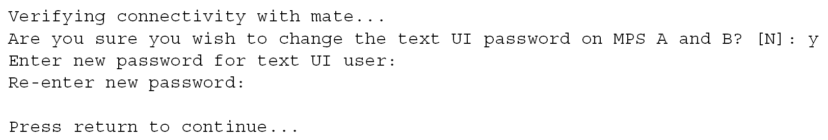
A.2.4.7 Change Password
The Change Password option 5 from the ELAP Configuration Menu changes the text-based user interface password for the elapconfig login name for both MPS A and MPS B.
See Figure A-19 for the option 5 output.
Figure A-19 Change Password
A.2.4.8 Platform Menu and Options
The ELAP Platform Menu option 6, from the ELAP
Configuration Menu, accesses the Platform menu so that the
elapconfig user can
access and manage platform functions. See Figure A-20 for
the option 6 output.
Figure A-20 Platform Menu Output
MPS Side A:  hostname: mps-a  hostid: 0
             Platform Version: 5.5.0-75.11.0
             Software Version: ELAP 10.0.0_100.13.0
             Wed Apr 10 09:34:14 EDT 2013

 /-----ELAP Platform Menu----------\
/-----------------------------------\
|  1 | Initiate Upgrade             |
|----|------------------------------|
|  2 | Reboot MPS                   |
|----|------------------------------|
|  3 | MySQL Backup                 |
|----|------------------------------|
|  4 | RTDB Backup                  |
|----|------------------------------|
|  e | Exit                         |
\-----------------------------------/

Enter Choice: 2
Initiate Upgrade
The Initiate Upgrade menu option 1 initiates an upgrade on the selected ELAP. For upgrade procedures, contact Customer Care Center.
Reboot MPS
The Reboot MPS menu option 2 initiates a reboot of either MPS or both. The default is BOTH.
Note:
Theelapconfig user can abort rebooting the MPS by pressing the Escape key at the displayed prompt.
Reboot MPS A, MPS B or [BOTH]:
Caution:
Rebooting the MPS stops all ELAP processes. Databases cannot be updated until MPS is fully booted.MySQL Backup
The MySQL Backup menu option 3 backs up the MySQL database.
Note:
ELAP software must be stopped or MySQL backup will abort and return to the ELAP Platform Menu.
Are you sure you want to back up the MySQL database on MPS A? [N]: y
Connecting to local MySQL server...
Getting read lock...
Tarring the NPDB...
Disconnecting from local MySQL server...
RTDB Backup
The RTDB Backup menu option 4 backs up the RTDB.
Note:
ELAP software must be stopped or RTDB backup will abort and return to the ELAP Platform Menu.
Are you sure you want to back up the RTDB database on MPS A to
"/var/TKLC/appl/free/rtdbBackup_mps-a_20050926110224.tar"? [N]: y
ELAP Platform Menu Exit
The Exit menu option e exits from the ELAP Platform Menu and returns to the ELAP Configuration Menu.
A.2.4.9 Configure NTP Server and Options
The Configure NTP Server option 7 allows for the display, addition, and removal of an external NTP server.
Figure A-21 Configure NTP Server Output

Display External NTP Server
The Display External NTP Server menu option 1 displays External NTP Server information. If a server is present, the server name and IP address are displayed. If an NTP Server is not present, the following message is displayed.
There are no External NTP Servers. Press return to continue... Add External NTP Server
The Add External NTP Server menu option 2 adds an External NTP Server.
Note:
The IP address must be a valid address for an External NTP Server.Are you sure you wish to add new NTP Server? [N]: y
Enter the ELAP NTP Server IP Address: 192.168.61.69
Verifying NTP Server. It might take up to 1 minute.
External NTP Server [server 192.168.61.69 prefer] has been added.
Press return to continue...
Verifying NTP Server. It might take up to 1 minute.
External NTP Server [server 192.102.61.91 prefer] has been added.Remove External NTP Server
The Remove External NTP Server menu option 3 removes an External NTP Server. If a server is present, selecting the Remove External NTP Server removes the server. If an NTP Server is not present, the following message appears:
There are no External NTP Servers. Press return to continue... ELAP Configure NTP Server Menu Exit
The ELAP Configure NTP Server Menu Exit menu option e exits the ELAP Configure NTP Server Menu, and returns to the ELAP Configuration Menu.
A.2.5 ELAP Configuration Procedure
Initialization and configuration are provided through a text-based user interface (UI) described in this chapter.
The first time user elapconfig logs into MPS A, the system performs an auto-configuration on both MPS ELAP pairs. The sync network and main and backup DSM networks are initialized to their default values, described in Network Connections and defined in Installation Guide for EAGLE. Various internal configuration parameters are also set to their default values. The installer must perform initial configuration on MPS A on EAGLE A and MPS A on EAGLE B.
A.2.5.1 Configuration Terms and Assumptions
-
The initial configuration steps assume that each MPS has previously undergone successful Initial Product Manufacture (IPM).
-
The network paths must be present and verified before the MPS servers are ready for configuration.
-
Initial configuration can be implemented on only the MPS A side of EAGLE A and MPS A side of EAGLE B. Attempting to perform initial configuration on MPS B of EAGLE A is not allowed, and the
elapconfiguser will be notified. The attempted configuration will be aborted with no impact on either MPS A or B.After the initial configuration of MPS A on EAGLE A and MPS A on EAGLE B, both ELAPs should be operational unless the system failed to successfully initialize during reboot or the configured values for the Sync and/or DSM networks conflict with other equipment in the network. Changing the default network values is not recommended.
-
The provisioning values displayed for the following initialization and configuration steps are example values only.
-
Default values can be accepted just by pressing the Return key at the prompt; default values are shown enclosed in brackets [ ].
-
The customer is responsible for determining the timing and frequency of performing database backups. Databases should be backed up when they are initially populated with data; however, the priority that the customer assigns to data and time lost in restoring the data dictates the frequency of database backups.
-
Adding an NTP server is optional. Additionally, only one NTP server is needed to provide time synchronization for all the MPS servers on both EAGLE pairs.
-
The ELAP terms local and remote are relative with respect to the ELAP configuration software. In other words, if the user is running the configuration software on the physical MPS (that is, the MPS that the user is physically on-site and has a terminal connected to), the configuration software refers to that MPS as local. However if the user connects through the network into the MPS A on EAGLE B, the configuration software executing at EAGLE B sees itself as local, and identifies the MPS to which the user is physically connected as the remote.
The local MPS is whichever MPS A that the configuration software is being executed on, regardless of where the user is physically located.
The MPS of EAGLE A is the first MPS to which the user physically connects and on which initial configuration of the ELAPs is always begun.
To avoid confusion of these relative terms, the MPS A on EAGLE A is considered to be the on-site MPS to which the user has the physical connection. This document refers to the MPS to which the user does not have the physical connection as MPS A on EAGLE B.
A.2.5.2 Configuration Symbols
During the Configuration Procedure, the installer will initialize and configure the MPSs to perform various functions. Special instructions are required occasionally for an MPS on EAGLE A, an MPS on EAGLE B. To assist the installer, this manual uses these symbols to indicate individual instructions to be performed for those specific MPSs.
Table A-5 MPS Configuration Symbols
| MPS Symbol | Symbol Description |
|---|---|
|
|
This symbol indicates installation instructions to be performed specifically for the MPSs (MPS A and MPS B) on EAGLE A. |
|
|
This symbol indicates installation instructions to be performed specifically for the MPSs (MPS A and MPS B) on EAGLE B. |


A.2.5.3 Initial Setup and Connecting to MPSs
Installation personnel may choose to employ various methods for connecting to an MPS. The ELAP software requires that an MPS be configured from side A. This procedure describes a likely method for connecting to EAGLE A and then EAGLE B. Installers require that all console output be captured.
A.2.5.4 Procedure for Configuring ELAPs
Perform the configuration procedure by following these steps in the text-based user interface. After you have connected to an MPS (as described in Initial Setup and Connecting to MPSs), you can perform this procedure to configure the ELAPs in your network.
Note:
Initial configuration cannot be performed through the GUI. The IP addresses required for browser connectivity are not defined until the initial configuration, using the text-based UI, is completed.Using the set up and connection described previously, the installer connects to an MPS to perform configuration. In a typical installation, the installer connects directly to the MPS at EAGLE A to configure it, then uses ssh to connect to the MPS at EAGLE B and configure it.
A.3 MPS Health Check Procedure
Run the syscheck utility to obtain the operational status of the MPS platform with the following procedure.
Refer to Login Screen and User Administration Menu for more details and information about logins and permissions.
For more information about the syscheck utility, see Alarms and Maintenance for ELAP.
- Log into the User Interface screen of the ELAP GUI as
elapplatform.The Main menu displays.Check the banner information above the menu to verify that you are logged into the correct ELAP.Figure A-22 Main Menu View
 The Platform folder opens.
Figure A-23 Platform Folder Open View

- When the GUI shows you are logged into the desired ELAP, select .The Run Health Check dialog opens.
Figure A-24 Run Health Check View
