3.2 Overall Design
The main functions of ELAP are:
-
Accept and store data provisioned by the customer from LSMS over the provisioning network
-
Update and reload provisioning data to the EAGLE Service Module cards.
The Multi-Purpose Server (MPS) hardware platform supports high-speed provisioning of large databases for the EAGLE. The MPS system is composed of hardware and software components that interact to create a secure and reliable platform.
During normal operation, information flows through the ELAP with no intervention.
ELAP provides two direct user interfaces for performing configuration, maintenance, debugging, and platform operations. See Overview of the ELAP User Interfaces.
Figure 3-1 illustrates a typical ELAP installation.
Figure 3-1 Typical ELAP Installation
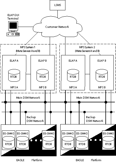
An MPS system consists of two mated EAGLE Application B Cards (E5-APP-B cards), which are MPS Server A and MPS Server B, installed as part of an EAGLE. Each server runs ELAP: ELAP A on MPS Server A and ELAP B on MPS Server B.
Two Ethernet networks, referred to as the A and B DSM networks, connect the Service Module cards and the ELAPs. Another Ethernet network connects the two ELAPs, and is referred to as the ELAP Sync network. (See Network Connections.)
Figure 3-1 shows the network layout. Table 3-3 shows examples of typical IP addresses of the network elements.
The ELAPs connect to the LSMS at ELAP initialization and receive provisioning data from the LSMS. The ELAPs store the provisioning data in redundant copies of the Real-Time Database (RTDB) and use the data to provision the EAGLE. Each Service Module card holds a copy of the RTDB.
The A and B DSM networks are redundant, load-balanced, 1GigE full duplex networks that carry provisioning data from the RTDBs on the ELAP to the RTDBs on the Service Module cards. If one DSM network fails, the Active ELAP uses the other DSM network to continue provisioning the RTDBs on the Service Module cards.
One ELAP runs as the Active ELAP and the other as the Standby ELAP. In normal operation, the RTDB on each Service Module card is provisioned through the DSM network by the Active ELAP. In case of failure of the Active ELAP, the Standby ELAP takes over the role of Active ELAP and continues to provision the RTDBs on the Service Module cards.
The LNP feature uses the “master” or “golden” Real-Time Database (RTDB) that is loaded from the ELAP to Service Module cards on the EAGLE. Up to 18 Service Module cards can be used to contain the RTDB on the EAGLE.
ELAP and the LNP feature support a maximum of 24 million to 756 million Telephone Numbers (TNs) in the RTDB. LNP quantity feature part numbers with feature access keys are used to enforce quantity limits. The LNP ELAP Configuration feature indicates that ELAP is used for LNP in the system. The LNP ELAP Configuration feature must be enabled before LNP can be enabled and must be turned on before LNP becomes operational in the system.
Two additional features, LNP NPANXX QTY, and LNP LRN QTY, regulate the maximum capacity allowed in the system and contain a finite increment of the quantity field.
3.2.1 Overview of the ELAP User Interfaces
ELAP provides two user interfaces:
- The text-based User Interface provides the Configuration menu and other menus to performs the ELAP initialization and first configuration. Use of the interface is described in ELAP Software Configuration.
- The Graphical User Interface provides GUI menus and screens that are used to maintain, debug, and operate the platform. The GUI and its associated error messages are described in this chapter.
Communication with the ELAP using either interface requires a PC connected to the MPS. The ELAP GUI Interface requires a network connection and a network browser. To set up a PC workstation, see Setting Up an ELAP Workstation.
3.2.2 ELAP Switchover
ELAPs assume an Active or a Standby role through negotiation and algorithm. This role impacts the way the ELAP handles its various external interfaces. External provisioning is allowed only through the Active ELAP. Only the Active ELAP can provide maintenance information to the EAGLE.
An ELAP can switch from an Active to a Standby role under the following circumstances:
-
The ELAP maintenance component becomes isolated from the maintenance component on the mate ELAP and from the EAGLE.
This implies that the maintenance subsystem has attempted and failed to establish communication with each of these:
-
The mate ELAP maintenance task across the Sync network
-
The mate ELAP maintenance task across the main DSM network
-
Any Service Module card on any DSM network
-
-
The RTDB becomes corrupt.
-
All of the UDT channels have failed.
-
A fatal software error occurred.
If the Active ELAP has one or more of the four switchover conditions and the Standby ELAP does not, a switchover occurs. Table 3-1 lists the possibilities.
Table 3-1 ELAP Switchover Matrix
| Active state | Standby state | Event | Switchover? |
|---|---|---|---|
|
No switchover conditions |
No switchover conditions |
Condition occurs on Active |
Yes |
|
Switchover conditions exist |
Switchover conditions exist |
Conditions clear on Standby; switches to Active |
Yes |
|
No switchover conditions |
Switchover conditions exist |
Condition occurs on Active |
No |
|
Switchover conditions exist |
Switchover conditions exist |
Condition occurs on Active |
No |
|
Switchover conditions exist |
Switchover conditions exist |
Condition occurs on Standby |
No |
|
Switchover conditions exist |
Switchover conditions exist |
Conditions clear on Active |
No |
The exceptions to the switchover matrix is:
- If the mate maintenance component cannot be contacted and the mate ELAP is not visible on the DSM networks, the ELAP assumes an Active role if any Service Module cards are visible on the DSM networks.
If none of the Standby conditions exist for either ELAP, the MPS servers negotiate an Active and a Standby. The mate is considered unreachable after two seconds of attempted negotiation.
3.2.3 Network Connections
This section describes the three networks and the IP address assignment for the networks that require them.
Table 3-2 Sample Network IP Addresses Configured from UI
| Network Connection | Sample MPS A Value | Sample MPS B Value |
|---|---|---|
|
Hostname |
MPSA-000000 |
MPSB-000001 |
|
Provisioning Network IP Address |
10.25.50.45 |
10.25.50.46 |
|
Provisioning Network Netmask |
255.255.255.0 |
255.255.255.0 |
|
Provisioning Network Default Router |
10.25.50.250 |
10.25.50.250 |
|
Sync Network IP Address |
169.254.1.100 |
169.254.1.200 |
|
DSM Network A IP Address |
192.168.120.100 |
192.168.120.200 |
|
DSM Network B IP Address |
192.168.121.100 |
192.168.121.200 |
Note:
These values are examples only. The values entered to configure the ELAPs are unique to each network configuration. The method to determine the actual network values is described in Hardware Reference.DSM Networks
The A and B DSM networks are redundant, load-balanced, 1GigE full duplex networks that carry provisioning data from the RTDBs on the ELAP to the RTDBs on the Service Module cards. These networks also carry reload and maintenance traffic to the Service Module cards. If one network fails, the other network carries all of the traffic normally carried by the both networks. Each network connects ELAP A and ELAP B to each Service Module card on a single EAGLE.
The first two octets of the ELAP network addresses for this network are 192.168. These are the first two octets for private class C networks as defined in RFC 1597.
The third octet for each DSM network is configured, usually to the default value .120 for the network A and the default value .121 for the network B. These are not visible to any external networks, and should not need to be changed.
The fourth octet of the address is selected as if:
-
ELAP is configured as ELAP A, the fourth octet has a value of 100.
-
ELAP is configured as ELAP B, the fourth octet has a value of 200.
Table 3-3 summarizes the derivation of each octet.
The configuration menu of the ELAP user interface contains menu items for configuring the ELAP network addresses. See ELAP Software Configuration.
Table 3-3 IP Addresses on the DSM Network
| Octet | Derivation |
|---|---|
|
1 |
192 |
|
2 |
168 |
|
3 |
Usually already configured as: 120 for DSM network A 121 for DSM network B |
|
4 |
100 for ELAP A 200 for ELAP B 1 - 25 for Service Module cards on the networks |
ELAP Sync Network
The Sync network is a redundant, 1GigE, bonded network that connects ELAP A and ELAP B on a single Multi-Purpose Server (MPS) system. This network provides a high-bandwidth dedicated communication channel for MPS data synchronization. The two ELAPs are connected using Telco switches over two Ethernet ports bonded together to provide redundant paths between the two MPSs.
The first two octets of the ELAP IP addresses for the Sync network are 169.254.
The third octet for each ELAP Sync network address is set to .1.
The fourth octet of the Sync network IP address is .100 for ELAP A, and .200 for ELAP B.
Note:
The Sync network IP address (169.254.1) is a link local IP address which can never be routed and cannot be changed.Redundancy in Synchronization Network
Redundancy in Synchronization Network enables the mate server to be reachable from the local server if the synchronization interface from the ELAP servers to any of the switches is not functioning due to problems with cable connectivity, the switch, or other synchronization network operations.
When the connectivity of the ELAP servers with Switch B is intact, the synchronization network operates through Switch B using the connection from Ethernet Port eth03 of ELAP A server to Port 3 of Switch B and from Ethernet Port eth03 of ELAP B server to Port 4 of Switch B.
If a connectivity problem develops from the ELAP servers to Switch B, the synchronization network continues to function using Switch A because of the synchronization interface on Switch A. The connectivity is from Ethernet Port eth04 of ELAP A server to Port 5 of Switch A and from Ethernet Port eth04 of ELAP B server to Port 6 of Switch A.
Provisioning Network
The provisioning network is the only network connected directly to the customer network. All provisioning information from the customer provisioning system travels over this network. In addition, all traffic required to keep remote MPS systems synchronized also travels across this network.
The provisioning (customer) network carries ELAP user interface traffic and traffic between ELAP and the LSMS.
The port is a 1GigE, auto-sensing device; it automatically runs as fast as the customer equipment allows. A dedicated network is recommended, but it is possible that unrelated customer traffic could also use this network.
3.2.4 LSMS-to-ELAP Connection
All normal LNP provisioning is conducted through the LSMS. Localized retrieval of data can be accomplished through the ELAP user interface.
The LSMS communicates only with the HA-Active ELAP in the MPS system using a Virtual IP (VIP) address interface. The LSMS connects to the HA-Active ELAP at initialization.
Although there are three ELAP states (HA-Active, HA-Standby, and Down) only the HA-Active member of the ELAP HA pair is connected to the VIP and listens for provisioning, audit and bulk download connections from the LSMS.
The LSMS provisions LNP data to the HA-Active ELAP across a TCP/IP connection in the customer network.
The LSMS collects subscription data from the Number Portability Administration Center (NPAC). It also collects local provisioning data (for default NPANXX, split NPANXX and other types of LNP records). This data is sent to the HA-Active ELAP, which performs minimal parsing and validation before updating its Real Time database (RTDB) and replicating the data to the mate ELAP RTDB. The ELAP with the LSMS primary connection ensures that the RTDBs on both ELAPs receive the provisioning data.
3.2.5 Network Time Protocol (NTP)
The Network Time Protocol (NTP) is a Internet protocol that synchronizes clocks of computers to Universal Time Coordinated (UTC) as a time reference. NTP reads a time server's clock and transmits the reading to one or more clients; each client adjusts its clock as required. NTP assures accurate local timekeeping with regard to radio, atomic, or other clocks located on the Internet. This protocol is capable of synchronizing distributed clocks within milliseconds over extended time periods.
If left unchecked, the system time of Internet servers will drift out of synchronization with each other.
The MPS A server of each mated MPS pair is configured, by default, as a “free-running” NTP server that communicates with the mate MPS servers on the provisioning network. (“Free-running” refers to a system that is not synchronized to UTC; it runs off of its own clocking source.) This allows mated MPS servers to synchronize their time.
All MPS servers running the ELAP application have the option to be configured to communicate and synchronize time with an LSMS server or with a customer-defined NTP time server. The prefer keyword prevents “clock-hopping” when additional MPS or NTP servers, LSMS servers for example, are defined.
If this optional feature uses an LSMS, the LSMS must be configured as an NTP server. Refer to LSMS Configuration Guide for configuration instructions. After the LSMS has been configured, configure the MPS servers to synchronize with the LSMS. See ELAP Software Configuration for instructions on configuring the MPS servers through the application user interface.
Understanding Universal Time Coordinated (UTC)
Universal Time Coordinated (UTC) is an official standard for determining current time. The UTC is based on the quantum resonance of the cesium atom. UTC is more accurate than Greenwich Mean Time (GMT), which is based on solar time.
The term universal in UTC means that this time can be used anywhere in the world; it is independent of time zones. To convert UTC to your local time, add or subtract the same number of hours as is done to convert GMT to local time. The term coordinated in UTC means that several institutions contribute their estimate of the current time, and the UTC is calculated by combining these estimates.
UTC is disseminated by various means, including radio and satellite navigation systems, telephone modems, and portable clocks. Special-purpose receivers are available for many time-dissemination services, including the Global Position System (GPS) and other services operated by various national governments.
Generally, it is too costly and inconvenient to equip every computer with a UTC receiver. However, it is possible to equip a subset of computers with receivers; these computers relay the time to a number of clients connected by a common network. Some of those clients can disseminate the time, in which case they become lower stratum servers. The industry-standard NTP is one time dissemination implementation.
Understanding NTP
NTP is an Internet protocol used to synchronize clocks of computers using UTC as a time reference. NTP primary servers provide their clients time that is accurate within a millisecond on a LAN and within a few tens of milliseconds on a WAN. This first level of accuracy is called stratum-1. At each stratum, the client can also operate as a server for the next stratum.
A hierarchy of NTP servers is defined with several strata to indicate how many servers exist between the current server and the original time source external to the NTP network, as follows:
-
A stratum-1 server has access to an external time source that directly provides a standard time service, such as a UTC receiver.
-
A stratum-2 server receives its time from a stratum-1 server.
-
A stratum-3 server receives its time from a stratum-2 server.
-
This NTP network hierarchy supports up to stratum-15.
Normally, client workstations do not operate as NTP servers. NTP servers with a relatively small number of clients do not receive their time from a stratum-1 server. At each stratum, it is usually necessary to use redundant NTP servers and diverse network paths to protect against broken software, hardware, or network links. NTP works in one or more of these association modes:
-
Client/server mode, in which a client receives synchronization from one or more servers, but does not provide synchronization to the servers
-
Symmetric mode, in which either of two peer servers can synchronize to the other, in order to provide mutual backup
-
Broadcast mode, in which many clients synchronize to one or a few servers, reducing traffic in networks that contain a large number of clients. IP multicast can be used when the NTP subnet spans multiple networks.
The MPS servers are configured to use the symmetric mode to share their time with their mate MPS servers. For an ELAP system, customers using the application user interface have the option to configure the MPS system to receive NTP from LSMS or a customer-provided NTP server.
3.2.6 Support ELAP Reload Via Database Image Function
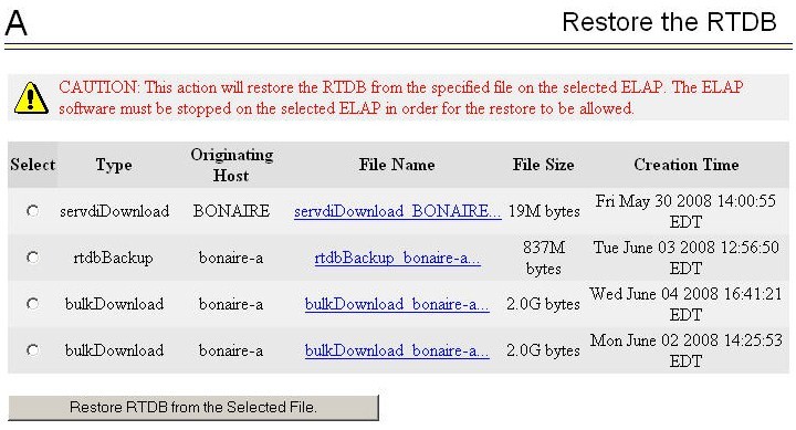
The Support ELAP Reload via Database Image (SERVDI) function performs bulk data downloads (BDD) that significantly reduce the time needed to reload an ELAP database. SERVDI is included with optional LNP feature.
The SERVDI function is executed on the LSMS system and creates an LNPRTDB image file directly from the LSMS LNP databases. The servdiDownload file must be transferred to the ELAP system backup directory. Once transferred, the file can be activated by using the restore from backup process in the ELAP GUI. For more information on the restore from backup process, refer to the "Restore RTDB on ELAP 9.0" section in LNP Database Synchronization User's Guide.
Note:
Although the exchange of ELAP Secure Shell (SSH) Keys is performed automatically by the configuration software at the start of the ELAP configuration, exchange of SSH keys with the LSMS must be performed manually for the ELAP to receive bulk downloads from the LSMS. See Procedure for Configuring ELAPs. The
key exchange must also be performed from the LSMS. Login as lsmsadm on the LSMS Active server CLI and execute the command
keyexchange elapdev@<ELAP VIP> to
exchange the key with the elapdev user.
See also Restore RTDB.
Figure 3-2 ELAP Restore the RTDB GUI with servdiDownload Option
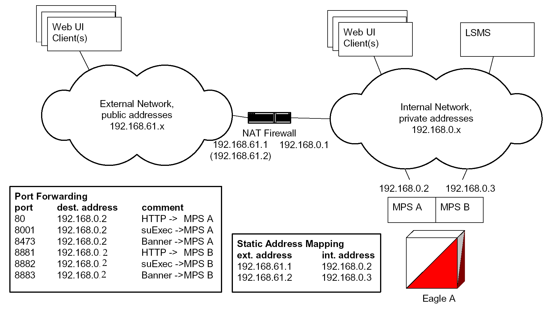
3.2.7 Network Address Translation on MPS
The MPS supports 2 types of network address translation (NAT), Port Forwarding and Static Address Mapping. In both cases, the MPS will have private IP addresses that are not available outside of the firewall protected internal network. The firewall will translate particular addresses and port numbers to the internal addresses for the MPS.
The addresses in Figure 3-3 are examples. Addresses are not restricted to particular classes/ranges.
Port Forwarding
Port Forwarding allows a single external address to be used for multiple internal systems. The Port Forwarding firewall maintains a list of services (basically port numbers) and corresponding internal addresses.
Although the MPS has two individual internal IP addresses, external clients are allowed to reach the internal network using only one external address. The MPS servers must use different port numbers for each externally available service in order to distinguish MPS A from MPS B to external clients.
The MPS uses 3 ports for the Web UI and another 2 ports for the LSMS and EBDA connections. At a minimum, one MPS side must be must be configured with 3 Web UI ports different from the default values. The firewall must be configured to forward 3 Web UI ports to MPS A and 3 different Web UI ports to MPS B.
The LSMS does not currently allow configuration of alternate LSMS and EBDA ports. Until this changes, the LSMS is required to be on the internal network of a Port Forwarding firewall. Do not change the default values for these ports.
Figure 3-3 NAT on MPS
Static Address Mapping
Static Address Mapping makes systems that are behind the firewall appear to have public addresses on the external network. A one-to-one mapping exists between internal and external addresses.
An external address must be assigned to the NAT firewall for each MPS side. The external addresses must be entered into the MPS database in order for the Web UI to be fully functional.
3.2.8 ELAP Security Functions
ELAP Security functions control access to an ELAP GUI to specific IP addresses. The specified allowed IP addresses are kept in an ELAP list and can be added to, deleted from, and retrieved only by an authorized user. These functions also allow an authorized user to toggle IP authorization checking on and off through the GUI.
The administrator or user with IP action privileges can add, delete, and retrieve IP addresses. Deleting an IP would result in that IP address no longer residing in the IP table, hence preventing that IP address from being able to connect to an ELAP.
Note:
While each of the IP action privileges can be assigned to any individual user, the IP action privileges of add and delete should be granted only to users who are knowledgeable about the customer network.The ability to add, delete, and retrieve client IP addresses and to toggle IP authorization checking is assignable by function. This is accessible through the ELAP GUI (see User Administration Menu). The IP mechanism implemented in this feature provides the user a means of further enhancing ELAP privilege control.
The ELAP Security functions are available through the ELAP GUI and are available initially to only the administrator. The ability to view IP addresses on the customer's network is a security consideration and should be restricted to users with administration group privileges. In addition, privileged users can prepare a custom message to replace the standard 403 Forbidden site error message.
Note:
IP access and range constraints provided by the web server and the ELAP Security functions cannot protect against IP spoofing. (The term ‘spoofing’ refers to the creation of TCP/IP packets using another's IP address; it is IP impersonation or misrepresentation). The customer must rely on the security of the customer’s intranet network to protect against spoofing.ELAP maintains a list of the IP addresses that are authorized to access the graphical user interface. Only requests from IP addresses on the authorized list can connect to the ELAP GUI. Attempts from any unauthorized address are rejected.
Note:
No IP addresses are restricted from accessing the ELAP GUI until the administrator toggles IP authorization to ‘enabled’. When IP authorization checking is enabled, any IP address not present in the IP authorization list will be refused access to the ELAP GUI.ELAP Security functions also provide the means to enable or disable the IP address list once it is provisioned. If the list is disabled, the provisioned addresses are retained in the database, but access is not blocked from IP addresses not on the list. The ELAP GUI restricts permission to enable/disable the IP address list to specific user names and passwords.
The IP actions for adding, deleting, retrieving authorized IP Addresses and for toggling authorized IP checking are available only from the ELAP GUI (described in Overview of ELAP Graphical User Interface), but not from the ELAP text-based UI described in ELAP Software Configuration.
3.2.9 LSMS/ELAP PING Enhancement
Depending on customer network architecture, the LSMS and ELAP may be on different internal networks. To increase security, as few ports as necessary should be required to be open inbound to the ELAP network. The original LSMS/ELAP interface supports a UDP PING function to monitor the connectivity between the two systems. The LSMS/ELAP PING enhancement feature moves the monitoring function within the HSOP interface, such that the UDP PING port is no longer required.
The LSMS continues to support the original UDP PING method to address operation with ELAPs that have not been upgraded, as well as continued UDP PING operation in conjunction with the HSOP keep alive.
The procedures to set up the LSMS/ELAP PING function are done on the LSMS.