Platform
The Platform section of the Settings window contains configuration options for defining the monitored SIP network. Operations Monitor requires this information for accurately mirroring SIP messages.
Platform Devices
The Platform Devices section is used to define the topology of the monitored network. This section defines the SIP devices and how they behave in order for Operations Monitor to properly merge calls and provide accurate overall and per-device statistics.
Figure 7-7 Platform Devices Settings

Table 7-4 Columns and Descriptions in the Platform Devices page
| Columns | Descriptions |
|---|---|
| Add | A wizard guides you through to add additional platform devices options. |
| Edit | To edit a device, double click its table row, or select the device and click the Edit button. A wizard dialog box opens, pre-filled with the current values for the selected device. |
| Delete | To delete a device, select it and click the Delete. |
| Import | Import a device configuration |
| Export | Export a selected device configuration as a .csv file or JSON file. |
Device Types
Operations Monitor supports the device types shown in Device Type Settings figure, and described in the table below. The Show in groups check box in the Platform Devices page, groups devices of the same type in a group.
Figure 7-8 Add a New Platform Device
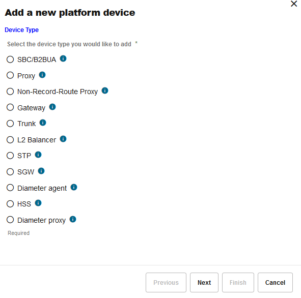
Table 7-5 Device Types
| Device Type | Description |
|---|---|
|
SBC/B2BUA |
Select this option for devices that terminate an incoming leg and originate one or more independent outgoing legs from the same call (creating at least two SIP sessions). Examples include, session border controllers (SBCs), application servers (AS), and private branch exchanges (PBX). Because a B2BUA works by accepting the incoming call leg as a UAS, and creating a new leg as a UAC, it is difficult to determine whether two call legs are part of the same call. Therefore, on selecting this option, the wizard displays more configuration options for merging the call legs. For more information Choose the 3PCC option for SBC/B2BUA devices that work as 3PCC servers. These servers create a call between two parties using two outgoing call legs. The configuration options are available in the 3PCC Options page. When the 3PCC option is enabled on a SBC/B2BUA device type, the OCOM must determine whether two outgoing legs are part of the same call. On selecting this option, a wizard displays more configuration options for 3PCC legs. If the device is capable of originating two outgoing legs with a common header in the context of the same call, only select the 3PCC option to configure. For Skype for Business calls, ensure that you configure the SfB Server as a B2BUA device. This is required for the outbound and inbound messages to be correlated and for the SfB calls to be shown as two distinct calls in the Calls page. This is shown in the Active Calls KPI. |
|
Proxy |
Select this option for devices that route calls without creating a new SIP dialog. The Call-ID in the outgoing call leg is usually left unchanged and SIP soft-switches and SIP layer load balancers are usually implemented as proxies. |
|
Non-Record-Route Proxy |
Select this option for devices that route INVITE messages but are skipped by the next messages in the dialog. These devices usually keep the Call-ID and the tag in the From SIP header field, as well as the URIs in the From and To headers unchanged. |
|
Gateway |
A SIP gateway is a device that connects the SIP platform to other types of networks (for example, PSTN, H.323). Operations Monitor only monitors the calls terminated and created by the gateway on the SIP side. Call merging is not created for gateway devices. If you need SIP/ISUP call merging, use an SGW (Signaling Gateway) device. |
| Trunk |
This is not a physical device, but a peering with other carriers in which the peering IP addresses are known. Operations Monitor can display the calls going to and from this peer, as well as statistics about them. In addition to static IP addresses, the trunks can be defined using the OTG and DTG URI parameters. |
| L2 Balancer |
A SIP load balancer acts at Layer 2 (of the OSI stack), keeping the IP addresses untouched and only modifying the hardware addresses. Operations Monitor supports these setups by identifying the devices by their hardware addresses in addition to the IP addresses. |
|
STP |
A Signaling Transfer Point (STP) monitors SS7/Sigtran routers and supports call merging for these protocols. |
|
SGW |
A Signaling Gateway (SGW) transfers between different types of protocols. These multi-protocol signaling routers convert between ISUP and SIP and allow call merging between different types of call signaling protocols. For more information, see. Note: A simple (or SIP) GATEWAY is always seen as a terminating device. |
|
Diameter agent |
Select this option if you are monitoring Diameter devices in Control Plane Monitor. For example, Mobile Management Entity (MME). |
|
HSS |
Select this option if you are monitoring Diameter messages exchanged with a Home Subscriber Server (HSS) in Control Plane Monitor. |
|
Diameter proxy |
Select this option if you are using an intermediate device to monitor a proxy that relays Diameter transactions in Control Plane Monitor. |
SBC/B2BUA Call Merging
Call merging across B2BUA devices is a crucial point for SIP troubleshooting. Operations Monitor can use a large set of criteria for matching the calls, has several easy-to-use presets, and can also combine the criteria in a very flexible way by using custom algorithm expressions.
For STP devices, a similar choice of options applies. For SGW devices, the only options are the default or custom matching algorithm.
The wizard panel offers the high-level options:
image
Figure 7-9 Choosing the Call Matching Type for a B2BUA Device
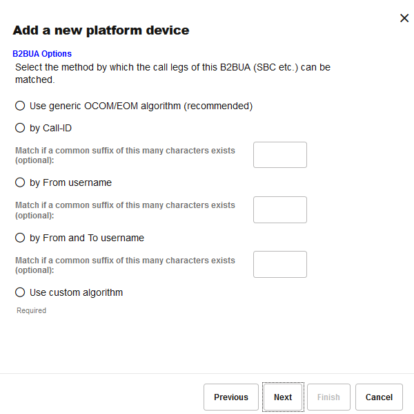
Table 7-6 B2BUA Device Options
| Option | Description |
|---|---|
| Use generic Oracle Communications Operations Monitor/Enterprise Operations Monitor algorithm (recommended) |
The algorithm was developed to accurately detect which call legs belong to the same call for the most common SBC/B2BUA configurations. The algorithm takes into account the time difference between the calls, the session-id from the SDP, the From and To users, the P-Asserted-Identity header, the Diversion header, etc. Oracle recommends using this option and to adjust if necessary. For more information about the generic algorithm, see "Call Merging Algorithms". |
|
by Call-ID |
To be used if the SBC/B2BUA is configured to copy the Call-ID header from the incoming call leg to the outgoing call leg. If the suffix parameter is given, then only the last suffix characters are compared. This is useful, for example, if the SBC/B2BUA only prepends a string to the Call-ID to make it unique. |
|
by From username |
To be used if the SBC/B2BUA is configured to keep the same From user between call legs, and this does not lead to false positives in most cases. If the suffix parameter is given, only the last suffix characters are compared. This is useful if the SBC/B2BUA only changes the prefix of the numbers (for example, from +49 to 0049). |
|
by From and To username |
To be used if the SBC/B2BUA is configured to keep the same From user and To user between call legs. If the suffix parameter is given, only the last suffix characters are compared. This is useful if the SBC/B2BUA only changes the prefix of the numbers (for example, from +49 to 0049). |
|
Use custom algorithm |
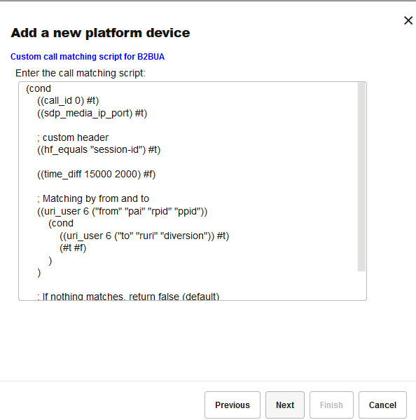
This allows flexible combining available criteria for matching, ordered tests, and nested tests, as well as matching on arbitrary SIP headers. For more information on how to write a custom algorithm, see "Call Merging Algorithms". If this is selected, another wizard panel will be shown for entering the algorithm. The Operations Monitor generic algorithm is pre-filled as a starting point. |
Figure 7-10 Entering a Custom Match Algorithm
3PCC Options
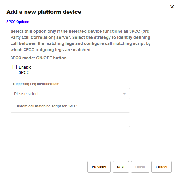
Third-Party Call Control (3PCC) servers initiate two outgoing legs to establish a single call between two parties. OCSM correlates the two SIP sessions using a custom header that is common to both outgoing legs. This feature is configurable per SBC/B2BUA device. The default value is disabled.
Figure 7-11 Configuring 3PCC Options
Identifying the Triggering Leg
The triggered leg or Callee leg is the leg that defines the call state. The other leg is the triggering leg or Caller leg. For example, a 3PCC server originates a call to both a SIP User Agent and a PSTN user. The outgoing leg towards the User Agent is the triggering leg and the outgoing leg towards the PSTN user is the triggered leg.
There are two ways to identify the triggering leg:
-
Hostname in
FROM and TO Headers being the same in INVITE: The INVITE in the
triggering leg contains the same hostname in the
FromandToheaders. - Provisional Response: The triggering leg generates a provisional response (18x) relatively faster than that of the triggered leg.
Select one of the strategies to identify the triggering leg.
Call Matching Script
The call matching script correlates the two outgoing legs in the context of 3PCC calls.
The following is the basic template for a call matching script.
(cond
  ((hf_equals <any 3PCC custom header>) #t)
  ((time_diff 2000 0) #f)
  ; If nothing matches, return false (default)
)
If the 3PCC header is
X-Genesys-CallUUID, the
script looks like the following.
(cond
  ((hf_equals "X-Genesys-CallUUID") #t)
  ((time_diff 2000 0) #f)
  ; If nothing matches, return false (default)
)
The functionality of
hf_equals() is
explained in the Call Merging Algorithms chapter, but the
time_diff() method
varies slightly in a 3PCC call matching script. The syntax is
time_diff(interval1,
			 interval2)
.
interval1- The maximum time difference between the initial INVITE message of one outgoing call leg and the initial INVITE of another outgoing call leg. The maximum value is 5 seconds.interval2- Since there won't be any matching incoming call legs for outgoing call legs in 3PCC calls, this value has no significance and is not used. Use the default value of 0.
Note:
The algorithm configured, in this 3PCC options page, will not be used to correlate incoming calls and outgoing calls.Enable the 3PCC option only when a device functions as a 3PCC server by originating two outgoing legs in the context of the same call. Because 3PCC is more resource intensive, choose this option only when needed.
Device Identification
The devices are usually identified by only their IP addresses. Exceptions are the trunk devices, which can be also identified by the OTG and DTG parameters, and the set-ups in which the hardware addresses are significant. Either IPv4 or IPv6 addresses may be supplied. IP ranges with bitmasks smaller than 24 (for IPv4) or 120 (for IPv6) might impact performance significantly.
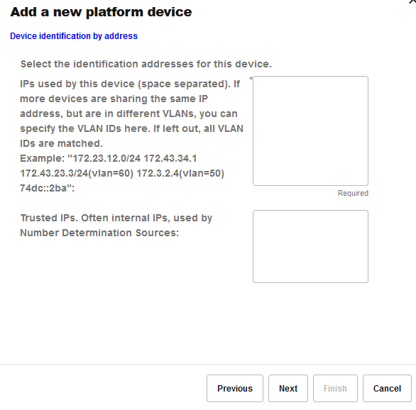
In the Device identification by address wizard panel, specify the identification addresses for the device you create. Enter the IPs used by the device in a list separated by spaces. If multiple devices share an IP address, but are in different VLANs, you can also specify the VLAN IDs.
You can specify VLAN IDs in multiple ways. You can enter:
-
IP(VLAN=x) with x>=0, which matches packets with VLAN ID x.
-
IP without a specified VLAN. The IP matches any packets, with or without a VLAN.
-
IP(VLAN=0) or IP(VLAN=off) which only matches packets with no VLAN. This restricts the IP to only non-VLAN packets.
Figure 7-12 Device Identification Settings
Identifying Trunk Devices
For trunk devices, there is also the option of identifying by using the OTG and DTG parameters, offered by an extra wizard panel.
Figure 7-13 Trunk Identification Settings
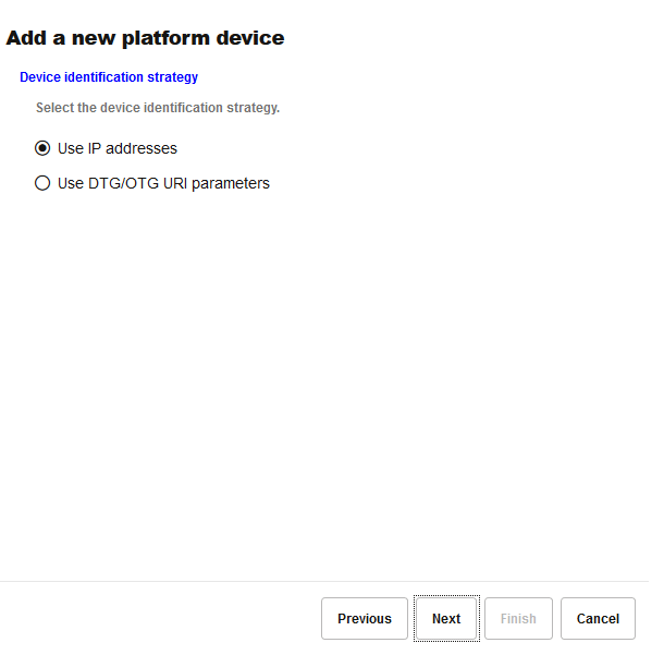
The parameters OTG and DTG are the originating and destination trunk identifiers found in the From header field of the URI, respectively, Request-URI.
Trusted IP Ranges
For the Number Determination algorithm, only these IPs (or point codes) on each device are considered when identifying a call. Set this field to the source IPs for messages that you wish to take number information from.
Providing a Name
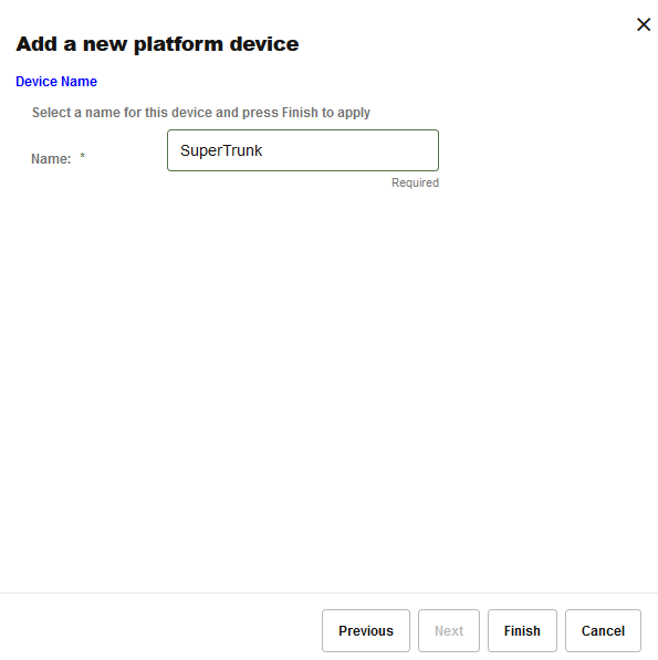
The last step in the creation wizard is to set a name for the device. The name may contain spaces, but it is recommended to keep the name short in order to fit in the table columns and SIP diagrams.
Figure 7-14 Device Name Settings
Visibility Configuration
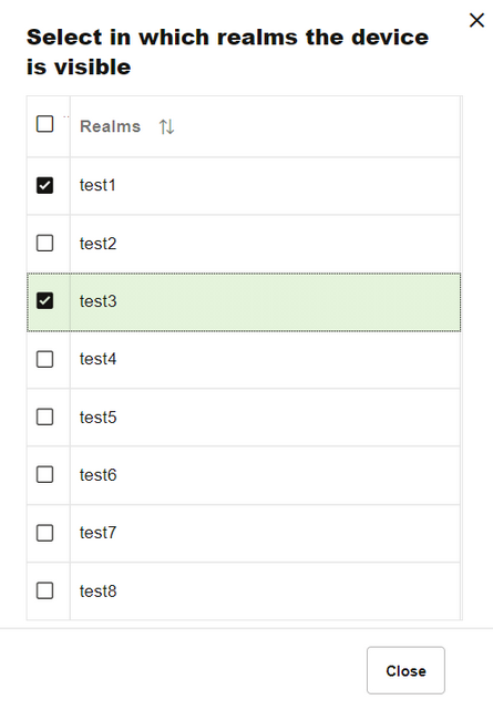
You can configure a device or trunk to be visible or hidden for each realm. Click the Realms button in the toolbar to list the current defined realms as illustrated. If one or more realms are checked, the device/trunk is visible only to the users belonging to those realms.
Figure 7-15 Device Visibility Settings
Configuring Devices for the Mediation Engine Connector
A Mediation Engine Connector allows a user to monitor multiple Mediation Engines that are located in separate geographic locations.
If a call is sent through a device monitored by two Mediation Engines, the Mediation Engine Connector sees the call flow through both Mediation Engines. In order for the Mediation Engine Connector to correlate the call, you must designate one Mediation Engine as internal, and the second Mediation Engine as external. The Mediation Engine Connector consolidates the data from both Mediation Engines and presents the single call flow.
The Toggle external button allows you to select a device and determine if the device is visible to the associated “internal" Mediation Engine, or visible to other “external" Mediation Engines in the Mediation Engine Connector platform.
For more information on correlation, see “Understanding Call Correlation" in “Configuring Mediation Engines" in Mediation Engine Connector User's Guide.
For more information regarding the Mediation Engine Connector, consult your Oracle representative.
Enabling or Disabling Device Map for a Device
A Device Map shows an overview of the status and activity for all configured devices on the monitored platform. You can enable or disable the display of a device in device map for a specific device in the Platform Devices page.
After upgrading to 4.4 from a previous release, with the Device Map Limit set to any value outside of the supported range, the Enabled device map flag is set to False and the individual Device Map Status for all devices in Platform Devices is set to Disabled. This is also applicable to the savepoint configuration from older releases that are restored in 4.4.
To enable Device Map for a device and to set the limit:
Configuring Devices for Voice Quality Measurement
The Voice Quality page lets you to view voice quality statistics based on the MOS, Packet Loss, and Jitter measures. For more information on voice quality, see "Voice Quality".
You can configure a device or trunk to be associated with either of the following voice quality (VQ) statuses.
If a device has no templates applied, then the VQ Status button is enabled for all such devices. If you have upgraded from OCSM 4.x to OCSM 5.0 release, all devices can still use this VQ Status button if no templates are applied. This ensures that you can apply VQ statuses for all the devices post upgrade.
If a device is associated with a template then the VQ Status button is disabled. You can still add VQ counters as part of a custom template for a device. For more information on custom templates, see KPI Templates.
-
No VQ: None of the VQ counters is enabled.
-
Only MOScqe: Only the MOS VQ counter is enabled and the other VQ counters gets disabled.
-
Full VQ: All three kinds of the VQ counters (MOS, Packet Loss, and Jitter) are enabled.
Note:
When you change the VQ status for a device from "Full VQ" to "No VQ" or "Only MOScqe", and from "Only MOScqe" to "No VQ", the existing VQ data of the "Full VQ" status and the "Only MOScqe" status is lost.Figure 7-17 Platform Devices Settings - VQ Status

Note:
If the VQ status displays the word "Partial" in red while associating a device with the VQ status, it implies there has been an issue causing the device counters to not match the VQ status. To resolve this issue, try setting VQ Status back to "No VQ" for the device using the Platform Device Settings page, and then again to "Full VQ" to re-add the VQ counter.Device Monitoring
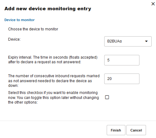
The Devices Monitoring page is used for starting monitoring a device defined in "Platform Devices". Monitoring is realized by counting the number of requests that remain unanswered.
Figure 7-18 Devices Monitoring Settings

Operations Monitor uses the following algorithm for monitoring SIP devices:
-
A counter is kept with the number of incoming SIP requests to the monitored device, which have received no answer. These requests are not sent by Operations Monitor, but are regular requests from the SIP network.
-
Whenever the monitored device sends a message (regardless of what type of message), the counter is set to zero, because the device must be up.
-
If the counter exceeds a configurable threshold, a timer is started to fire after a configurable time interval.
-
If the monitored device sends a message before the timer fires, the timer is canceled and the counter is set to zero again.
-
If the timer fires, the monitored device is marked as down.
Enabling Device Monitoring
In the Device Monitoring table, each line represents a device being monitored. To enable or disable the monitoring of any device, select the device in the table and click the Toggle Enabled button in the toolbar. The Enabled? column from the table shows the current status.
Adding and Editing Monitored Devices
Before you add a device to be monitored, you must configure the device in the Platform Devices settings section.
To add a new monitoring configuration, click the Add button from the upper toolbar. A wizard dialog guides you through the monitoring options.
To edit an existing monitoring configuration line, select the device and click the Modify button in the toolbar. A wizard dialog opens pre-filled with the current values for this monitoring configuration. If you want to permanently delete a configuration type for a device, select it from the table and click Delete.
Note:
Device monitoring does not affect the performance or stability of the monitored device. It is immune to connectivity problems between the monitoring and the monitored device, reducing false positives.
Device Monitoring Parameters
To configure a device monitoring, a couple of parameters are requested:
-
Device name to be monitored.
-
Expiry interval of the timer.
-
Number of unanswered requests needed to start the timer.
Additionally, you can enable device monitoring immediately, or leave it disabled until toggled from the list of monitored devices.
Figure 7-19 Device Monitoring Parameters
IP Tags
The New IP Tag Management window is used to add new IP addresses.
Figure 7-20 Adding a New IP Tag
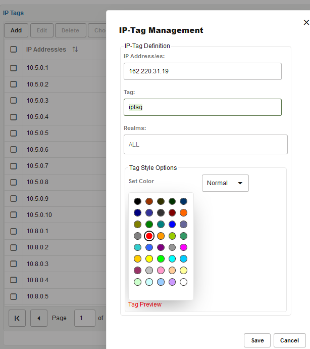
IP tags are a way of assigning friendly names to IP addresses or IP subnets (either IPv4 or IPv6). The IP tag's name appears in brackets in the Call Details window. The color and font style of the tags can be customized. IP tags are visible and editable by all users.
You can assign KPI templates to IP Tags. For more information on Choose Template, and Assigned template, see KPI Templates.
Prefix Tags
The Platform: Prefix Tags window is used to add new Prefix tags.
Figure 7-21 Adding a New Prefix Tag
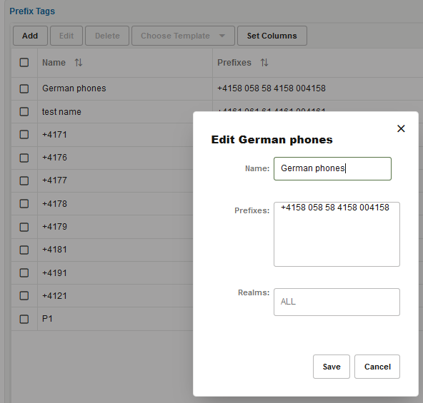
Prefix tags allow assigning a friendly name to phone prefixes. Once the prefix tag is created, the user can create a KPI or metric on. You can, like with devices, configure a prefix tag to be visible or hidden for each realm, with the difference that prefixes in the ALL realm won't be visible for the user in another realm. For more information, see "KPI/Metrics".
When a prefix tag KPI is created in a realm, the value of the KPI is sourced from the calls matching both the prefix and the realm pattern. If you create a prefix tag in one realm and a KPI in a different realm, the KPI will not be visible to users who are restricted to one of the two realms.
You can apply KPI templates to Prefix tags. For more information on Choose Template, and Assigned Template, see KPI Templates.
Note:
You can create a prefix tag using a maximum of 6 characters (including the "+" character if it is needed). For example, 493080.Realms Definitions
You configure Realms Definitions under the Realms section of the Settings menu. Each realm can have one or more realm patterns associated with it.
Realms can be used for limiting the visibility of Operations Monitor's web interface users. They are useful in scenarios such as:
-
You have a set of resellers of the SIP service, and you want to give each of them the monitoring abilities of Operations Monitor, but at the same time restrict their view only to the SIP users served by them.
-
You have a set of support workers, and you want to give them the fast troubleshooting abilities of Operations Monitor, but in the same time restrict their view to a certain set of users, for privacy reasons.
A realm can be defined as a set of telephone numbers or as a set of domains. The set of rules defining a realm are called realm patterns. Additionally, a custom header in SIP can contain a realm identifier.
Note:
Realms do not need to be disjoint. For example, you can have a single telephone number in multiple realms, and you can have one realm containing the union of other two realms.
If a user has his or her visibility restricted to one realm:
-
The user only sees the registered subscribers that are part of the realm. The User tracking feature is restricted as well.
-
The user only sees calls in which the caller or the callee are part of the realm.
-
Statistics are adjusted to reflect only the Realm section, not the whole platform. For example, the Active Calls chart counts only the active calls in which one of the participants is part of the realm.
Note:
Voice quality statistics are an exception. Realm separation does not apply to voice quality statistics. Users assigned to realms see platform wide voice quality values.
-
If the user creates a trace, it will only contain the messages that are from or to subscribers of the realm.
-
Alerts are only sent to the user if the cause of the alert is part of his realm.
In other words, realms are segments of the subscriber base, and if an Operations Monitor user's view is restricted to a realm, Operations Monitor will only show information about that segment.
Note:
Realm names cannot be deleted, only the realm patterns.
Realms are not the only way to limit the view of the web interface users. You can also restrict features by using user rights. For more information, see "User Management".
Realms Table
The Relams panel used for adding, editing and deleting realms. Realms can also be created from the Realm Patterns Table edit window. Deleting a realm will also delete all its associated patterns.
Note:
When deleting a realm, in case there are devices associated with that realm, a warning is displayed showing these devices.
It is the user's responsibility to remove these devices manually. Otherwise, the devices would be still available in the Platform Devices settings section without any realm assigned.
Figure 7-22 Realms Definitions

Realm Patterns Table
The Realm Pattern Definitions page shows the panel used for defining realm patterns. Selecting a realm pattern and then clicking the toolbar Edit button, or double-clicking an entry opens an editing window.
This table describes the fields found in the Add new realm pattern table:
Table 7-7 Add a New Realm Pattern Fields
| Field | Description |
|---|---|
|
Rid |
The ID of the realm. |
|
Realm |
The name of the realm. The edit select menu of the field offers the previous used realms, but also allows entering a new name. By entering a new name and pressing the Create button, a realm with that name is created immediately. |
|
First number |
The first phone number from a number range realm. If this is specified, then the Last number must also be specified. The realm will contain all numbers from the range. |
|
Last number |
The last phone number from a number range realm. If this is specified, then the First number must also be specified. The realm will contain all numbers from the range. |
|
Domain |
The domain from a domain restricted realm. The realm will contain all the users from the given domain. This can be combined with the First number and Last number options in which case all restrictions apply. If the First number and the Last number are provided, the caller or callee number must be in the range between those values. If Domain (optional) is provided, then the number must be in between the First number and Last number. Additionally, the domain must match the value provided in the Domain field. Therefore, between First number, Last number, and Domain, there exists an AND relationship. The caller or callee information must fulfill all the conditions to be assigned to the realm. |
|
Custom Pattern |
Give a custom header pattern for matching of calls to this pattern. If a call's invite contains this header pattern then it is counted in the realm. For more information, see Realms Header Specification. You can also provide a Custom Pattern. For Custom Pattern, either the First number, Last number, and Domain OR the Custom Pattern must match. For a Custom Pattern, there exists an OR relationship. |
|
Creator |
The user who created this realm. |
|
Comment |
(Optional) Comment line, only for convenience. |
Note:
In order for the domain restricted realms to work, Operations Monitor needs to be configured to consider the domains in the user identifiers. Set the Use User Domains to true. For more information, see Use User Domains.Note:
Configuring a large number of realm patterns will affect the performance of the server.Figure 7-23 The Add or Edit Realm Pattern Window
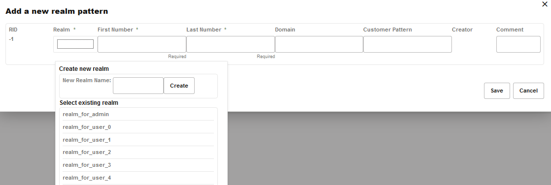
Figure 7-24 Realm Patterns Definitions
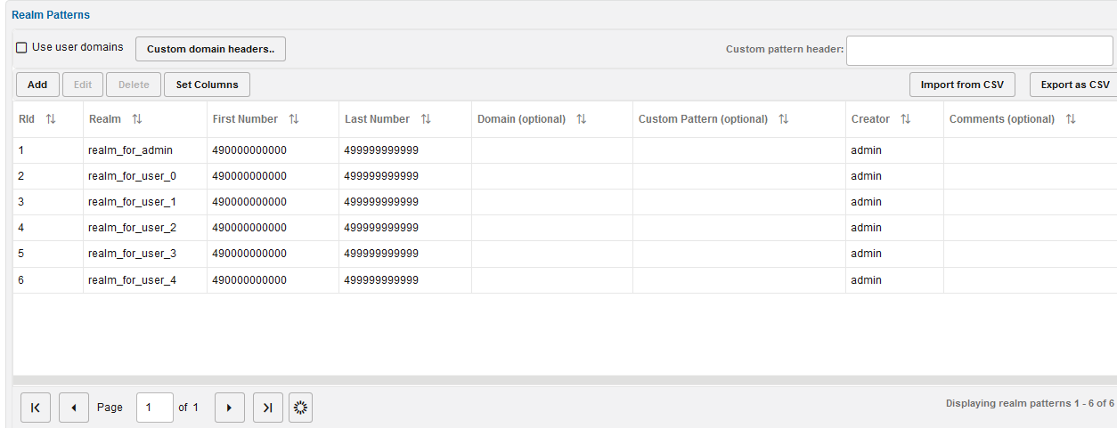
For example, the configuration from the Realms Patterns page defines the realm reseller A to contain:
-
The phone number range 00491234000 to 00491234999, regardless of the domain name.
-
The phone number range 0301234000 to 0301234555, regardless of the domain name.
-
All users that have a.sip.palladion.net as their domain name.
The realms configuration can be exported to and imported from CSV files. This simplifies the realms maintenance in case of many realms patterns. For example, the configuration in Realm Pattern Definitions would be exported to:
name,min,max,domain,comments
reseller A,00491234000,00491234999,,
reseller A,0301234000,0301234555,,
reseller B,0301234556,0301234999,,
reseller B,,,b.sip.palladion.net,
reseller A,,,a.sip.palladion.net,
test,00445213000,00445213500,,Test realm with a single number.
The realms patterns can also be provisioned automatically by uploading a similar CSV file via FTP.
Realms Header Specification
There are two System Settings that modify the way Operations Monitor assigns realms to calls. By default Operations Monitor checks the To: and From: header for each SIP invite message associated with a call and associates this call with all matching realms (“or").
Specify additional header fields in the System Setting named Headers in which to look for realm URIs. Diversion or P-Asserted-Identity could be useful values, depending on the configuration. Operations Monitor generally checks all the occurrences of each of these fields in each SIP Invite message. Exceptions are possible for header fields whose repetition is forbidden by the SIP standard.
Further customizing is possible by matching a custom pattern against an arbitrary header field. Use the Custom header for realm definition System setting to specify which header to search for; use the Custom Header Pattern (optional) column on the Realms Definitions page to specify a pattern for each realm. The pattern matching works similar to the number matching.
Be aware that each additional header and the custom header matching are affecting Operations Monitor's performance.
Automatic Realm Pattern Import
You can create an external list of realm patterns and import the list into Operations Monitor. You can compose a list as a CSV file, upload the file by using FTP, and configure Operations Monitor to have the CSV file processed at a defined interval to import the realm patterns.
This is an alternate method of adding realms to Operations Monitor. Importing realm patterns from an external CSV file may be preferable if you have a large number of entries to add or if you make frequent changes to the realm definitions. See "Realms Definitions" for more information on adding realms using the Operations Monitor interface.
Caution:
Importing new realm patterns overwrites existing realm patterns. The import feature is not additive; rather, all numbers for all realms should always be present in the CSV file.
About Formatting the CSV File
Each line in the CSV file contains the realm name and the number pattern separated by a comma.
For example:
RealmName, NumberPattern
Assign each realm name and number pattern a unique value and order the list alphabetically. Only enter single number entries (even if there are number ranges belonging to the realm). Do not include duplicate entries. The import function of Operations Monitor compacts the numbers to the least possible amount of patterns by grouping them into the ranges.
Following is an example of a list of realm names and number patterns:
03940394, 444333222111
40404044, 404040404040
realmone, 133334444555
realmone, 133334444666
second, 12224444333
Sorting Realms
If you are unsure of the uniqueness or ordering of realm names and number patterns, you can use the UNIX sort function on the file you have created.
From the command line, enter:
/var/vsi/ftp/realms# cat list.csv | sort -u > ordered_list.csv
The listing of users can be sorted on name, email, or realm.
When sorting on realm, ALL comes first (or last, respectively), even if there is an entry coming alphabetically before ALL. Similar logic applies for realm NONE, which, however should never appear unless you have a broken database or misconfiguration.
If you use the sort function in Operations Monitor, use the command to remove the original list after the sorting is complete. Since all entries must be unique, allowing the original list to remain following the sort would introduce duplicate entries. The original list would also exist in an unsorted state.
Run the following command to remove the original list:
/var/vsi/ftp/realms# rm list.csv Importing Realms at a Daily Frequency
You can set a specific time at which the new realm patterns are automatically imported each day.
To enable importing realms at a daily frequency, at the command line:
-
Create a folder within the FTP directory:
mkdir /var/vsi/ftp/realms -
Open the etc/iptego/vsp.conf file and add the following text:
[realms]
import-enabled=1
import-task-hour=hour
import-task-minute=minute
The hour and minute variables indicate the hour of the day and the minute of the hour that the feature processes the CSV file. Valid values for the hour field are 0 through 23. Valid values for the minute field are 0 through 59.
The following example schedules an import to take place every day at 03:10 a.m. server time:
import-enabled=1
import-task-hour=3
import-task-minute=10
-
Save and close the file.
-
Restart the respective process to make above changes active:
systemctl restart pld-vsp.service
Editing the CSV File
Edit the CSV file externally, then recommit it by using FTP to the realms folder. Make sure the CSV file is ordered and with unique entries. On the configured import time, the change will take effect.
There can be multiple CSV files present in Operations Monitor. Ensure that the entries are unique across all the CSV files.
