9 Sender and Receiver Data Transfer Interface
-
Sender
-
Receiver
The Interface is very complex and changing any of its settings arbitrarily could result in data not transferring across successfully. It is therefore recommended that Oracle Hospitality Cruise is informed before making any serious changes. Among the changes to coordinate are moving the Interface to another computer, changing the operating system (OS) of the computers or queue names, running the Interface, or modifying the transfer setup in FMS_TRANSFER table.
Also, note that increasing or decreasing the Batch Size for different tables or the Thread counts should not be done merely because the option exists. Its settings are based on a lot of testing and changing these could result in longer transfer times, bottlenecks on the satellite and exhausting the resources of the computers running the Interface or the Database Server. Furthermore, Oracle Hospitality Cruise recommends that even general setup changes from within the Interface should be coordinated and carried out by one designated person for the whole fleet.
When setting up the interface, do take into consideration the use of Mod Date Adjustment Hours described below which apply to both the Sender/Receiver Data Transfer.
MOD DATE ADJUSTMENT HOURS: This is a negative number defining the number of overlapping hours from the last transfer date and time. When the daily scheduled transfer takes place, it picks up data that has been modified since the last transfer date for each table it has to transfer. So if the last transfer time was at 04:00 hrs of the previous day, the Interface picks up all data modified from 01:00 hrs of the previous day. This accommodates most scenarios involving time changes, modifications done during transfer.
Configuring Sender
-
Go to
C:\Program Files (x86)\Oracle Hospitality Cruise\OHC
FMS Sender
. -
Open OHC FMS Sender.Config file and update the ServiceUrl.
-
Set the flag Y/N IsActiveDirEnabled.
-
Set the flag Y/N isShipSide.
-
Save the settings.
-
Set the TNS Names File and the Data Source.
-
Login with your user name and select the appropriate schema name.
-
Click Apply to save the settings and launch the FM Sender application.
-
Click the Settings tab and select the desired destination.
-
Right-click the Queue Info window and add a new Queue.
The settings are saved in an XML file called ConfigSettings. The password is saved in a 128 bit encrypted form. You can always modify these settings by clicking on the Config Settings button under the Settings tab of the OHC FMS Sender.
Note:
You must restart the interface for the settings to take effect if you modify any of the settings or add new queue entries.Activity Status
The Activity Status shows the activity status of Fleet Management Sender and the Log Header tab shows the log of the Sender. Both are also used by Support team for debugging.
Table 9-1 Activity Status
| Activity Status | Description |
|---|---|
|
Direction |
The transfer tables are divided into various groups for ease of transfer settings. Each direction above shows a different set of tables. The settings of tables are explained later in the Settings tab. |
|
Status |
The status of the direction group that is being transferred. |
|
Last Transferred Date |
The last date in which the data was transferred for that Direction Group. |
|
Next Transfer At |
The next scheduled date and time in which the next transfer would take place for that Direction Group. |
Table 9-2 Columns of the Data Grid
| Columns | Description |
|---|---|
|
Destination |
Receiving end of the transferred data. |
|
Direction Group |
The direction group of data that is being transferred. |
|
Ship |
Ship number. |
|
Table |
Table that is being transferred from the visible direction group. |
|
Transferred On |
Date along with time on which the table is transferred. |
|
Batch |
Each transfer table is divided into batches for transfer. The batch number getting transferred and the total number of batches shows up here. |
|
Records |
The number of records transferred of the batch. |
|
Remarks |
Any error/warning or remark of the batch being transferred is shown. |
Settings
The Settings tab shows the direction groups, the transfer timings and MSMQ level information. Direction groups can be added/edited and configured from here.Table 9-3 Direction Groups
| Name | Description |
|---|---|
|
ShipToShore |
Selection of tables that need to be transferred once a day. Set to transfer at 5 AM daily. |
|
Setup data |
All tables requiring transfer more than once a day. For example, table that gets changed frequently and /or impact the business. Set to transfer every 3 hours. |
|
Lob data |
All tables with Blob/picture fields are transferred separately as they take more time to transfer. They are also set to transfer once a day. Set to transfer at 6 AM daily. |
|
Trans-tables |
Contain the settings related to transfer tables. These tables are used by support team for investigation problems. Set to transfer at 8 AM daily. |
Config Settings
This setting allows you to change the settings such as SMTP or schema info.
To modify the config settings, click the Settings, then Config Settings. The General settings are thread level settings of the interface.
Table 9-4 SMTP Details
| SMTP Details | Description |
|---|---|
|
Server IP Address |
IP address of the email server. |
|
Server Port |
The default is 25. Change if it is different for your mail system. |
|
Email From |
From identifier of the email sender. For example, Test FM Sender. |
|
Email To |
Email address of the receiving group/person. |
|
Attach Error File |
Checking the Attach Error File would attach the error file to the email and the email would be sent to the defined email addresses. |
|
Schema Info |
Gives the information of the database schema sender is sending data from. |
Setup and Configuration
Microsoft Message Queuing (MSMQ)
The Interface sends messages over MSMQ in compressed and encrypted packets. The responsibility to successfully deliver the packet to the destination queue lies within the MSMQ architecture, which in turn relies on the network connectivity provided between the source and destination. Since ships send data over satellite and this connectivity may drop at any time, MSMQ holds the messages at the source until it re-establishes connectivity and then sends it across, thereby ensuring a successful transfer of every packet.
The Interface transfers data in two modes:- Workgroup and Active Directory (AD). AD mode is a secure mode where messages are encrypted and authenticated using the certificates on the Domain Controller.
Note:
AD mode requires installation of MSMQ on the Domain Controller. It only works if the Sender and the Receiver machines are in the same domain.The MSMQ
component needs to be installed on every machine that runs OHC FMS
Sender/Receiver. Since it is NOT installed by default, it has to be
installed later from the Windows Components under Add/Remove
Programs. During the installation process, make sure ALL
sub controls of MSMQ are installed, and you must select Integration
with Active Directory if the data transfer in AD mode is
required.
A typical one-way communication requires the queues to be created only at the Receiving end, logically this would imply shore side. But if the solution requires a two-way communication, a queue also needs to be created onboard to handle any incoming messages. At the shore side, a queue should be created for each ship.
MSMQ Settings in Workgroup Mode
-
Expand Message Queuing and right-click Private Queues.
-
Select New, Private Queue. The queue is to remain as non-transactional.
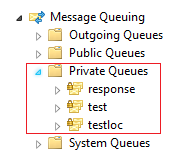
Figure 9-1 MSMQ Private Queue List

The local computer or the domain user can run the Sender/Receiver in workgroup mode and create send queues or receive data using private queues. Additionally, user is required to create a response queue to receive responses from data transferred.
MSMQ Settings in AD Mode
- Login to your machine as a domain user, go to Computer Management, select Services and Applications
-
Expand Message Queuing folder, and right-click Public Queues.
-
Select New, Public Queue. The queue is to remain as non- transactional.
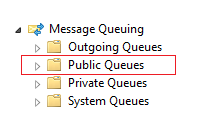
Figure 9-2 MSMQ Public Queue List

Creating Queue Settings in both Workgroup mode using private queues allow the domain user to run Sender/Receiver in both modes (Workgroup and AD mode). The AD mode uses public queues to send or receive data. Also, an additional private response queue (Workgroup mode) and public response queue (AD mode) are configured to receive responses.
Sender Settings
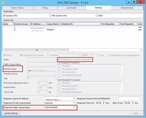
Figure 9-3 Sender Settings Screen

-
AD Mode: Required to Enable Active Directory Integration and select Response Public Queue name.
-
Workgroup Mode: Select Response Private Queue Name.
Since the use of MSMQ is not limited to only Fleet Management, it is recommended to use intuitive queue names to reflect the locations they represent. For example, a fleet with three ships called MV Sun, MV Moon and MV Cloud, the queue names could be FMsun, FMmoon and FMcloud. However, to meet an operator’s compliance guidelines, the names can be set as desired.
At the ship-side, when using two-way communications, the queue is expected to be utilized for administrative system messages. Oracle Cruise naming standard for this queue is FMdata, but like other shore-side queue names, this can be changed to meet a company’s needs.
At queue creation, journaling must be enabled on all FMS MSMQ queues and validate that the queues were created as Non-transactional.
Important:
See Oracle Hospitality Compatibility Matrix for compatible operating system and database clients..When setting up the Interface Servers/PCs that runs the two components of the FM Transfer Interface, one must ensure that there is proper connectivity between the source and destination PCs. This can include troubleshooting routing and firewall.
Note:
While the Interface has been successfully tested on Windows 2019 and Windows 2022 platform, it is recommended to run the latest certified Windows OS, as each higher version of the OS supports a higher version of MSMQ which provides additional administrative functions for the Interface to manage the queue.Interface Preparation and Best Practices
The below listed item is the general practices for any Fleet Management System interface clients.
Turn Off Windows Updates
To ensure all day/every day of uninterrupted processing at the Interface, turn off Windows Updates. Invoke Automatic Updates from the Control Panel to modify settings accordingly.
Important:
The Customer must be informed, so that Technical Administration can be coordinated periodically.Prerequisites
There are separate program executables or installers for both the Sender and Receiver components. Both have its prerequisite for it to be installed and run. You must install the .NET Framework 4.6.1 or higher version before continuing to run the setup file or installers as these are built upon its architecture.
Receiver
The Receiver is the second part of the FM Transfer Interface since it can act only if the Sender has sent any messages to its receiving queues. The Receiver continuously looks for messages within the queues defined in its Settings tab and processes them upon arrival. Like the Sender, the Receiver is a multi-threaded application that can process many messages simultaneously from many queues. Due to the administrative actions that need to be carried out on the receiving queues, the Receiver is limited to working with the queues on its OWN PC (or server). It can NOT work with queues that are setup on remote machines.
See Configuring Sender section for configuration steps and below table for configuration settings..
Note:
If you have modified any of the settings or new queue entries were added, the Interface must be restarted for these settings to take effect.Table 9-5 Config Settings
| Configuration Setting | Description |
|---|---|
|
Root Path |
The Root Path is usually the folder where the executable resides. This is use by the Interface to create the sub-folders/directories where the Activity logs and Exception Log is written. |
|
File Retention Days |
This number defines the days that the log files are retained. Logs greater than the days mentioned is purged. |
|
Thread Pool Max Thread Count |
The Receiver uses multi-threading technology to process many tables simultaneously at a great speed. This number defines the count for the maximum threads that it opens at any given time. This number is usually derived based on the total tables to transfer + configuration of the PC running the Receiver + the configuration of the database servers since each thread makes its connection to the database. The Receiver divides the total threads by the total number of queues to process so all queues get equal resources and all are processed simultaneously. |
|
Enable Tracking Service |
This option allow you to dictate whether to launch the Tracking Service and check if the Receiver is alive or not. If the Receiver is closed gracefully, the service writes an Informational message in the Application Event log and stops. If the Receiver is forcefully closed, the service writes a Critical Error in the Application Event log and stops. This Service can then be managed through any Operational Management tool that sends alerts as required. |
|
Schema Info |
In this grid, the database connection is defined. The TNS
Names file must first be selected to enable the Interface to provide
a list of all possible DB connections. This file typically resides
in the |
Fleet Management Receiver
The Fleet Management screen shows the following tabs:
Table 9-6 Tabs and their description
| Tabs | Description |
|---|---|
|
Activity Status |
The Activity Status tab shows the current activity performed by the FMS Receiver. It also provides some other relevant information like the date and time of the last transfer and next transfer. The grid itself is self-explanatory and gives a running count and description of each message being processed. |
|
Log Reader |
The Log Reader tab enables retrieval and viewing of activity details of any old log file. A browser can be invoked to select the appropriate log file for viewing. Note: A new log file is created daily and named accordingly. All logs are saved in XML format. Logs are retained inC:\Program Files (x86)\Oracle Hospitality
Cruise\OHC FMS Receiver\queue-name\Log sub-folder/directory
for the respective queue.
Important: There are no automated procedures to purge log files. You must perform periodical disk clean-up for disk-space availability. |
|
Setting |
The Settings tab is the place to set up all the queues that you want the Receiver to process. |
|
Queue Info: This panel enables the user to provide the necessary information to define new queues. Note: Be aware that a PC (or server) can have more than one IP address. Additionally, if this is enabled, it could have IP version 6. |
|
|
Time Blocking: This panel enables the user to add time-slots that restricts the Receiver from processing any messages. This functionality is provided to accommodate customers’ DB maintenance windows. The Receiver initiates the Stop Receiving command 5 minutes before the start of any time block. |
|
|
Administration |
The Administration tab currently provides only 2 options; to stop or to start the Receiving process. When the Receiver application starts, the Receiving process starts by default. If for any reason, the Receiver needs to be put offline, just click Stop. The process will stop after processing all remaining messages in the memory. To start the receiving again, just click Start |
Adding Queue Info
-
Right-click into the grid and select Add.
-
Right-clicking on the specific queue enables the edit function, and brings the cursor to the lower half of the panel where you can select the correct IP address of the current machine.
-
Select a valid IP address. List of respective Private Queues are populated.
-
Select the correct queue and click Apply.
Syncing Data
- Select a Date from the calendar view and then click OK. If no specific tables are selected in the left-pane (not recommended during a historical database synchronization process), the system will prompt for a confirmation.
- If user click Yes, it will update
the
Fidelio.FMS_Transfer.LAST_TRANSFEREDfor all the tables. - Proceed to the Manual Transfer, and leave the default select box From Last Transferred.
- Click Transfer to commence the data transfer process, and the application reverts to the Activity Status.
- The listed Status shows Transfer in progress … immediately after Validating Transfer Table …, and the data-synchronization commences.
Tracking Record (Batch Level)
The batch level tracking records is a feature of Sender and Receiver. This section explains the tracking process and how to configure the tracking record.
Record Level Tracking Process
For records level tracking, the columns in FIDELIO and FCONSOL Schema are as follows:
-
SUCCESS_ROWS >> FMS_TRAN_LOG
-
STATUS >> FMS_TRANS_AUDIT
-
ERROR>>FMS_TRANS_AUDIT
-
REMARKS>>FMS_TRANS_AUDIT
Status column is marked as required, and the initial status is 0. The receiving side status became 7 or 8 (depending upon success or error) and the same is applied to the sending side. The Sending side will retain records whose status is <>7 for resending.
The record level tracking process is as follow:
- Sending Side: ACC >> Records in a Batch ID. For example, there are 10 records that has status initial as 0 in the fms_trans_audit table. Each record in trans_log with the same batch_id will be inserted as batch level information and send to the Receiver on the Receiving Side.
- Receiving Side: Receiver processes the batch_id and inserts 10 records in the fms_trans_audit table. For example, if two (2) of the records are Error and 8 records are Success. The Receiving Side will send the same status to the Sender as a Response message.
- Sending Side: The Sender processes the response message and marks the status in the fms_trans_audit on the Sending Side. Each of success record is marked as 7 and it will be deleted. For each of error record, it is marked as 8 and the Sender will resend the failed records until they are fixed.
Note:
Some errors may require the help from support team or a Database Administrator (DBA). For instance:-
When you try to add data to a mandatory column but the column is missing from the database table.
-
The FMS Transfer entries were incorrect.


