3 Projects
This chapter describes information for:
Working with Projects
A project is used to configure the structure of an application. Each project represents a single, logical RPASCE application; however, one or more applications may reside on one PDS instance. The hierarchies, dimensions, styles, and taskflow are defined within a project and are available for use within all solutions in a given project.
Note:
A solution can use a subset of the hierarchies and dimensions defined within the project. Within a project, you can additionally define certain properties (which are part of the Data Interface Tool) that describe how measures will be loaded into the application.
The RPASCE platform data is stored in a PDS instance. Only during PDS initial creation and patching, a simple domain is created from the application configuration. This simple domain is also referred as “sandbox” and is used for further building/patching the PDS instance. After the PDS instance is built/patched, RPASCE data is manipulated directly through the PDS instance instead of the sandbox.
Hierarchies are application-specific, which means that they are defined at the project (application) level and can be used by all solutions that are defined within that project (application). There is no requirement that each solution use all of the hierarchies defined in the project.
For example, a project may contain five hierarchies and three solutions, but each solution might only use four of those hierarchies in the base intersections of its measures, so even though five hierarchies exist, each solution may not use all of them.
Create a Project
Complete the following steps to create a project.
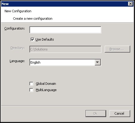
Navigate: From the File menu, select New and then Project, or right-click in the Configuration Manager and select New and then Project. The Figure 3-1 opens.
-
In the Configuration field, enter the name of the configuration/project.
The Use Defaults option under the Configuration field points the user to a default path for storing the configuration. Clear the Use Defaults check box to enable the user to navigate to the appropriate directory using Browse.
-
Select the default language for the application in which this configuration will be used to create. The default is English.
-
The options of Global Domain and MultiLanguage are deprecated and no longer configurable. The change of this setting has no effect in RPASCE.
-
Global Domain – The Global Domain setting is internally hardcoded to False since the starting sandbox is created as a simple domain.
-
MultiLanguage – The MultiLanguage setting is internally hardcoded to true since RPASCE applications are built to be multi-lingual. Multi-lingual applications allow for most data elements in an RPASCE application to be translated into another language. The translation process is managed by the Oracle translation group and is handled as a separate agreement with Oracle.
-
-
Click OK to save any changes and close the window.
Save Changes to a Project
Navigate: From the File menu, select Save, or right-click in the Configuration Components pane and select Save. This saves the project under the same name that was used to create it and within the same directory.
Using the Save As Option to Save a Project Using a Different Name
Complete the following steps to use the Save As option to save a project using a different name.
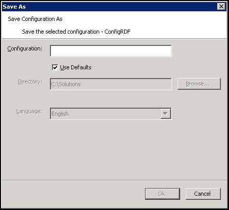
Navigate: From the File menu, select Save As, or right-click in the Configuration Components pane and select Save As. The Save As window opens.
-
In the Configuration field, enter the new project name.
-
If Use Defaults is selected, click OK to save the project to the path displayed in the Directory field. If Use Defaults is selected and you want to save the project to a different location, clear Use Defaults and either enter the appropriate path in the Directory field or click Browse to navigate to the appropriate location where you want the project saved.
-
Click OK to save the project.
Open an Existing Project
Complete the following steps to open an existing project.
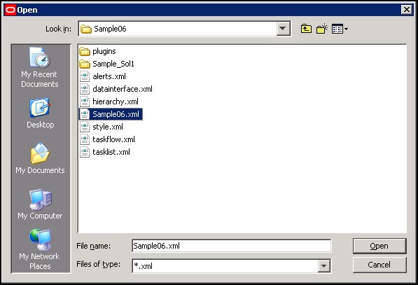
Navigate: From the File menu, select Open or right-click in the Configuration Components pane and select Open. The Open window opens.
-
Choose one of the following methods:
-
Browse to the directory where your project is saved. Select the file whose name is the same as the project with an
.xmlextension and click Open. The project displays in the Configuration Components pane. -
To open a project that was recently opened, select the project from the recently used projects list in the File menu. These projects display as a numbered list where the most recently used project is first in the list. Select the project to open in the Configuration Components pane. The number of projects that display in the most recently used list may be changed from the Workbench Preferences window, which is accessed by selecting Tools Preferences from the File menu.
-
Open an Existing Project from an Older Version of the Configuration Tools
If you attempt to open a project saved in a previous version of the RPASCE Configuration Tools, a window may open that allows you to convert the configuration to the new version.
Complete the following steps to open an existing project from an older version of the Configuration Tools.
Navigate: From the File menu or right-click from the Configuration Components pane, select Open. The Figure 3-3 opens.
-
Choose one of the following methods:
-
Browse to the directory where your project is saved. Select the file whose name is the same as the project with an
.xmlextension and click Open. The project opens in the Configuration Components pane. -
To open a project that was recently opened, select the project from the recently used projects list in the File Menu. These projects will be in a numbered list where the most recently used project is first in the list. Select the project, and it opens in the configuration manager. The number of projects that opens in the most recently used list may be changed by using the Tools Preferences option of the File menu.
A message box opens:
Figure 3-4 Convert This Configuration Message Box
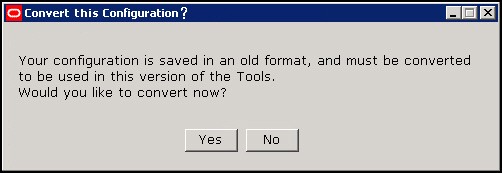
Description of "Figure 3-4 Convert This Configuration Message Box" -
-
To convert at a later time without currently viewing or modifying the project, click No. Click Yes to convert the project so it can be viewed or modified. If Yes is selected, the Figure 3-5 opens.
Figure 3-5 Choose a Backup Location Message Box
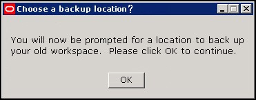
Description of "Figure 3-5 Choose a Backup Location Message Box" -
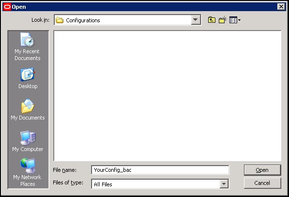
Click OK. The Figure 3-6 opens and prompts you for a location to store a backup of the project that is to be converted.
Figure 3-6 Open Window for Saving Configuration Backup
Description of "Figure 3-6 Open Window for Saving Configuration Backup"Note:
You may either rename the original configuration that is to be backed up or specify a new directory to store the original.
-
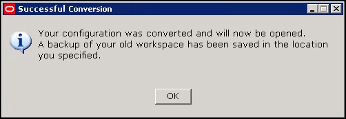
Select the directory to store the backup and click Open. The conversion process begins. If the conversion successfully completes the following message displays. Click OK to continue and view the project.
An error message opens if this process fails. The original project remains untouched and it will not open.
Close a Project
Complete the following steps to close a project.
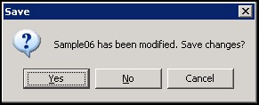
Navigate: From the File menu or right-click from the Configuration Components pane, select Close. If no changes were made to the Project, the project is closed. If changes were made, the Figure 3-8 opens.
Complete one of the following options:
-
Click Yes to save the changes made to the project and close it.
-
Click No to discard the changes made to the project since the last save and close it.
-
Click Cancel to return to the configuration manager without closing the project.
Understanding Hierarchies
A hierarchy is a top-to-bottom set up of parent-child relationships between elements of the same type. Hierarchies provide a means to define relationships between dimensions (aggregates, roll-ups, and alternate roll-ups) and groups belonging to the same entity (for example, Time = years, months, weeks, and days).
The following hierarchies are automatically created and cannot be deleted within the Configuration Tools:
-
CLND (Calendar)
-
PROD (Product)
-
LOC (Location)
-
ADMU (User)
-
LNGS (Languages)
These hierarchies are required by RPASCE-based solutions and cannot be removed, but additional hierarchies can be added to support the required business process.
Hierarchies define the path of data aggregation and spreading. In a workbook, the configuration administrator can view data at any required level of detail by drilling down or rolling up through dimensions in the hierarchy.
Note that ADMU and LNGS are not configurable hierarchies; therefore, they cannot be created or modified. ADMU and LNGS are built by RPASCE, and the RPASCE Configuration Tools makes them available for use in configurations. ADMU is the user hierarchy, and it exists to allow a measure to use the user dimension as part of its base intersection. LNGS is the language hierarchy, and it exists to support translation in multi-language applications. It is also available so that you can create a measure with the language dimension as part of its base intersection.
You can create and define dimensions for each of these hierarchies and for any additional hierarchies that are added to the project.
Note:
The names for the automatically generated hierarchies (CLND, PROD, LOC, ADMU, and LNGS) cannot be changed, but the default user labels for CLND, PROD, and LOC (Calendar, Product, and Location) can be changed. The user labels of ADMU and LNGS cannot be changed.
The CLND, ADMU, and LNGS hierarchies must exist in all applications, but PROD and LOC are not mandatory. If there are no dimensions created for the PROD and LOC hierarchies, the hierarchies are not created in the resulting PDS.
RPASCE does not impose any limit on the number of hierarchies that can be configured in a project. .
Configuration of Attribute Hierarchy Information
Dimension Attributes provide the ability to specify information about attributes that describe the positions within a hierarchy. For instance, Product Hierarchy positions may be represented by attributes describing color, brand, material, and so on.
Some applications that support processes that are heavily attribute driven make use of a construct often called an Attribute Hierarchy. An attribute hierarchy commonly contains two dimensions: a base dimension whose positions correspond to defined values for attributes and a parent dimension whose positions represent the attributes used by the application.
Using the color attribute as an example, an application containing an attribute hierarchy for Product would define positions for blue, green, red, and so on, on the attribute value dimension, which would then roll-up to the color position of the attribute position.
The existence of the attribute hierarchy allows applications to provide configured content that is aware of attributes and can use the values of attribute as an input into application processes. Examples of such functionality include rules whose execution logic depends upon the attribute values of the positions being evaluated or the ability to allow users to select attribute values from a drop-down list (as opposed to typing the attribute values into a text field.)
In order to leverage the existence of attribute hierarchies and to allow platform functionality to make use of the information contained within attribute hierarchies to simplify and improve the workflow of users, the hierarchy definition tool supports associating an attribute hierarchy with the hierarchy for which it provides attribute information.
In the previous example, an application contains an attribute hierarchy PATH (for Product Attribute) that contains information about attributes of the product hierarchy. By specifying PATH in the attribute hierarchy property of the product hierarchy, the configurer can provide this information to the platform so that core platform features can make use of the attribute information contained within PATH.
Figure 3-9, Figure 3-10, and Figure 3-11 illustrate how to configure the dimension attribute in Configuration Tools.
Figure 3-9 Associate Hierarchy to Attribute Hierarchy

Description of "Figure 3-9 Associate Hierarchy to Attribute Hierarchy"
Figure 3-10 Associate Attribute Measure to Dimension

Description of "Figure 3-10 Associate Attribute Measure to Dimension"
Configuration of Virtual Hierarchy Information
Applications such as IPOCS-Demand Forecasting sometimes require mirrored hierarchies and dimensions replicating other hierarchies and dimensions for their business logic. For example, IPOCS-Demand Forecasting contains both PROD and PROR hierarchies, while PROR mirrors the PROD hierarchy. Measures can be registered at an intersection that combines the PROR and the original PROD hierarchies. Workbooks can also have worksheets defined on the PROR hierarchy.
The mirrored hierarchy is called the virtual hierarchy of the original hierarchy, and the dimension within the mirrored hierarchy is called the virtual dimension of the original dimension. In the IPOCS-Demand Forecasting example, PROR is the virtual hierarchy of PROD, and the dimensions along the PROR hierarchy are the virtual dimensions of the dimensions along the PROD hierarchy.
With Virtual Hierarchy, the mirrored hierarchy can be implemented as a simple alias of the original hierarchy instead of as a complete individual hierarchy. Whenever any dimension of the virtual hierarchy is accessed, the accessor is automatically directed to the original dimension. Since the virtual hierarchy is simply an aliased version of the original hierarchy, what happens to the original hierarchy is immediately reflected in the virtual hierarchy. Virtual Hierarchy configuration avoids loading the essentially same hierarchy twice and improves performance in many ways.
The user must configure the virtual hierarchy and the virtual dimension in the Hierarchy Definition window (more details are provided in later sections). In a built RPASCE PDS, a virtual hierarchy is simply an alias of the original hierarchy, including all the dimensions. The virtual hierarchy and all its dimensions do not maintain their own position set and dimension dictionary in an RPASCE PDS. They always reference the original hierarchy's position set and dimension dictionary. Any changes made to the original hierarchy/dimension will then be automatically reflected in the virtual hierarchy/dimension. In the built workbook, the virtual hierarchy will be materialized and become a real hierarchy as part of the workbook build, so there will be no virtual hierarchy within the workbook. This is because the workbook may require the original and the virtual hierarchies to have different ranges. In the case of IPOCS-Demand Forecasting, the two ranges are complimentary, so it is possible that there is no common intersection in positions.
The positions in the virtual hierarchy and the virtual dimension inherit the translation from the original hierarchy and dimension, and there is no need to load the translated labels for the virtual hierarchy and the virtual dimension.
Virtual Hierarchy and Dimension Constraints
The following constraints apply:
-
Cannot be defined for RPASCE internal hierarchies.
The virtual hierarchy can be defined for regular loaded hierarchies such as product, location, and calendar, but cannot be defined for RPASCE internal hierarchies such as Meta, Data, Rgps, and so on.
-
Virtual in PDS only and not in the workbook.
The virtual hierarchy and dimension are only virtual in the PDS. They cannot be virtual in the workbook because the mirrored dimension may have a different range than the original one. In the workbook, when the workbook property Sync DPM to Virtual Dimension is not set, if the user adds a DPM position to the original dimension, the position will not be available in the same workbook, although it will be immediately available in the PDS’s virtual dimension. To pull the new position into the mirrored dimension in the workbook, the user must rebuild the workbook.
Users can set Sync DPM to Virtual Dimension property to true to synchronize DPM positions created on the original dimension to the virtual dimension at the end of the DPM creation process in the same workbook. Refer to Sync DPM Positions to Virtual Dimension section in Chapter 4 for details.
-
No DPM support for virtual hierarchies in workbook.
Users must only do DPM on the original hierarchy.
-
Cannot be partitioned.
RPASCE only allows one partitioning dimension in one PDS configuration. So even though the user can define a virtual hierarchy for PROD, the virtual hierarchy will not be partitioned.
-
Cannot be considered as Calendar.
This is the same as the as partitioning issue. Within the RPASCE application, only one hierarchy can be considered as Calendar. Note that the hierarchy name must be
clndfor it to be considered as Calendar. Even though the user can define a virtual hierarchy mirroring the calendar, the virtual hierarchy cannot be considered as Calendar nor used for calendar functions. -
Cannot share dimension attributes, images, or any measure-based data with its original hierarchy in the workbook.
A measure registered against the original hierarchy is not accessible for the virtual hierarchy in the workbook. The original dimension and the virtual dimension may have different ranges in the workbook, so data stored for the original hierarchy will not be available for the virtual hierarchy in the workbook. The virtual hierarchy must define and manage its own data, such as attribute, images, and so on, as long as they are stored in measures.
-
Dynamic hierarchies and hier mods not supported for the virtual hierarchy in Workbook.
In the workbook hierarchy pane of the Workbook Designer, the dynamic hierarchies and hier mods are unavailable for virtual hierarchies. If such functions are required, they must be provided on the original hierarchy. It is preferable that the virtual hierarchy be presented in its original topology.
The Hierarchy Definition Window
The Hierarchy Definition window allows you to define and construct hierarchies, dimensions for each hierarchy, and the relationships between dimensions. It also offers the following features:
-
Provides a visual representation of a hierarchy and its dimensions
-
Provides a means to define the hierarchy data load file
-
Allows existing hierarchies/dimensions to be reused in a new solution in the same project
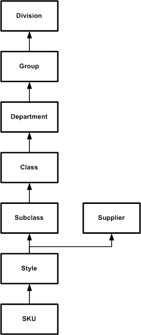
The Figure 3-12 diagram represents a typical structure of an organization's product hierarchy.
In the Figure 3-12 example, the Style dimension has two parents: Subclass and Supplier. Each position in the Style dimension will have a parent position in both the Subclass and Supplier dimension.
About the Hierarchy Definition Window
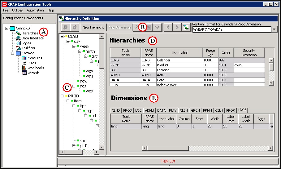
To access the Hierarchy Definition window, select Hierarchies (A) from the Configuration Components pane. The Hierarchy Definition window opens in the workspace.
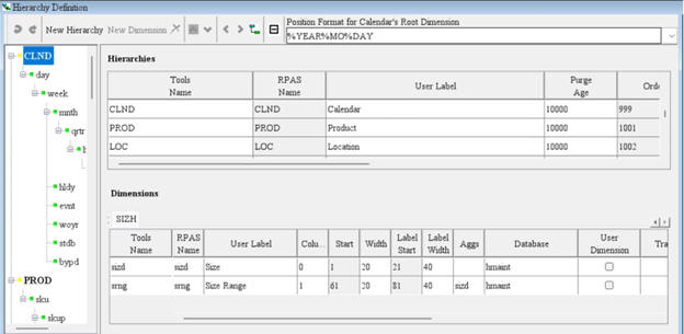
Figure 3-13 Example of Hierarchy Definition Window
Description of "Figure 3-13 Example of Hierarchy Definition Window"
The Hierarchy Definition window contains the following elements:
Table 3-1 Hierarchy Definition Window Elements
| ITag | Element | Description |
|---|---|---|
|
A |
Configuration Components pane |
|
|
B |
Hierarchy Definition toolbar |
This toolbar displays options that can be performed. Buttons are enabled or unavailable based on the item selected on screen. |
|
C |
Hierarchy navigation tree |
The navigation tree provides a visual representation of your hierarchies. Bold elements at the top of the tree structure represent the hierarchies. The items listed underneath each bold hierarchy are the dimensions defined in that hierarchy. Click Plus or Minus to expand the tree. The Hierarchy tree is also used to select a hierarchy or hierarchy dimension. Once an item is selected, you can modify its properties from the Dimension region in the Hierarchy Definition window. The Hierarchy navigation tree also provides a context menu when you right-click a tree item. The available options in the context menu depend on whether a hierarchy or dimension is selected. This context menu can be used to create a new hierarchy or dimension at the selected level. It also allows you to rename the selected item. When an item is renamed from the tree, it is the Tools Name that is being modified, which displays in the Dimensions region of the window. |
|
D |
Hierarchies region |
This area displays the defined hierarchies and their properties. |
|
E |
Dimensions region |
This area contains hierarchy tabs and allows you to define the dimension properties for your hierarchies. The tabs represent the hierarchies defined. Select the appropriate hierarchy tab to display its dimensions and modify dimension properties. |
Gray fields in the Hierarchy Definition window indicate fields that cannot be modified. Any elements that display in red indicate problems or issues must also display in the Task List pane along with a brief description of the issues identified.
Working with Hierarchies
This section describes how to:
Create a New Hierarchy
When a new project is created, following default hierarchies are automatically created: Calendar (CLND), Product (PROD), Location (LOC), User (ADMU), and Languages (LNGS). Additional hierarchies and dimensions can be created to meet your business needs.
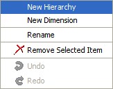
Navigate: Select New Hierarchy from Hierarchy Definition toolbar, or from the Hierarchy Definition tree, right-click and select New Hierarchy from the menu.
Note:
If multiple projects are open, make sure you are working from the desired project before adding a new hierarchy.
Modify the Tools Name
To change the Tools Name of the newly created hierarchy in the Hierarchy navigation tree of the Hierarchy Definition window.
-
Choose one of the following methods:
-
Right-click on the hierarchy name and select Rename.
-
Double-click the hierarchy name.
-
-
Enter the new name.
Note:
The RPASCE name can only be up to four (4) characters long.
-
Press Enter or click outside the hierarchy name.
Specify Hierarchy Properties
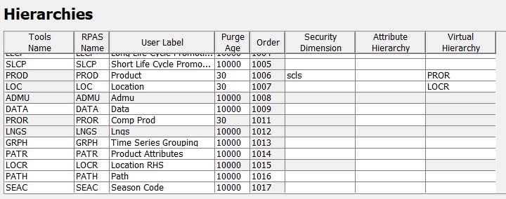
Hierarchy properties are defined from the Hierarchies region on the Figure 3-15.
Note:
Adding new hierarchies and new dimensions to an existing hierarchy are supported during patching. The new dimension can be either a root dimension, a leaf dimension or a dimension in between.
From this location you can modify the following hierarchy properties:
Tools Name
The name of the hierarchy that displays within the RPASCE Configuration Tools. This field is less restrictive than the RPAS Name field, allowing you to view and select a meaningful label for hierarchies and dimensions while working with the configuration rather than using the RPAS Name.
RPAS Name
The RPAS internal name of the hierarchy. This hierarchy name is used only by RPASCE (not the user) within the application.
Note:
The RPAS Name of a hierarchy cannot be edited if it is shaded gray; however, you can change other properties, such as User Label.
CLND is always the innermost dimension. The order of the other hierarchies (PROD, LOC, and so on) can be changed.
User Label
The hierarchy label that is displayed to RPASCE users within the application.
Purge Age
The purge age determines when a position and its corresponding measure data are removed from a PDS instance. Specifically, it represents the number of days before the data is purged from the last time the position was included in the hierarchy input file that is loaded with the loadHier utility during a batch run (most commonly on a nightly or weekly basis). Setting this value to zero means that a position and all of its data will be immediately purged if it is not included in the hierarchy file.
Note:
The value set in this field serves as the default value to use when
loading the corresponding hierarchy. This value can be overwritten
by one of the arguments of the loadHier utility each
time the utility is called. See the Oracle Retail Predictive Application
Server Cloud Edition Administration Guide for more information
on the loadHier utility.
Example 1: A purge age of 0 will purge positions the first night they are not in the input file.
Example 2: A purge age of 1000 will purge the positions the 1000th night after they are last seen on the input file.
Order
Hierarchy order determines the ordering of dimension fields in the physical storage of data in the RPASCE PDS instance. This ordering is the traversal order of data for calculations, which relates to how RPASCE iterates over data when performing calculations. Data in the PDS is stored in Oracle database tables that have columns representing dimensions, with each dimension belonging to a different hierarchy.
To change the order of a hierarchy, select the hierarchy from the Hierarchies region or from the Hierarchy navigation tree and use the up and down arrow buttons located on the Hierarchy Definition toolbar to move the hierarchy to the desired location.
The hierarchy can also be arranged by dragging and dropping in the Hierarchy navigation tree. The order numbers are automatically changed and generated regardless of the utilized reordering technique.
For performance reasons, the Calendar hierarchy (and therefore all of its dimensions) is always the innermost dimension and defaults to an unedited number of 999. The ordering of any hierarchy can be changed with the exception of Calendar (CLND). The lower the order number, the nearer the hierarchy is to the innermost dimension.
Consider the following example for the Calendar, Product, and Location hierarchies:
-
CLND order = 999
-
PROD order = 1001
-
LOC order = 1002
-
Two products: P1 and P2
-
Two locations: L1 and L2
-
Two calendar periods: C1 and C2
The sequence of physically storing and iterating over the data with calendar as the innermost dimension and location as the outermost dimension is:
C1,P1,L1
C2,P1,L1
C3,P1,L1
C1,P2,L1
C2,P2,L1
C3,P2,L1
C1,P3,L1
C2,P3,L1
C3,P3,L1
C1,P1,L2
C2,P1,L2
C3,P1,L2
C1,P2,L2
C2,P2,L2
C3,P2,L2
With Calendar being the innermost dimension, data is first processed for all positions in the Calendar hierarchy and for the first position of the other hierarchies. In this example, data would be processed for all calendar positions for the first product and first location. This is followed by all calendar positions for the second product and first location, and so on.
It is recommended that retailers order their hierarchies with Calendar as the innermost dimension (required), followed by other hierarchies in their order of importance/traversal – most commonly Product, Location, and then other hierarchies (if applicable).
Note:
Certain RPASCE-based solutions (such as Advanced Inventory Planning and Demand Forecasting) have additional hierarchies that are in a predefined order that should not be changed.
The Order column also indicates the order in which the hierarchy information is expected in the file used for measure data loading purposes.
Note:
The values 1000 or 1020 are not used as a hierarchy order as they are used internally by RPASCE.
CLND is always the innermost dimension and ADMU is always the outermost dimension.
The order of the other hierarchies (PROD, LOC, and others created by the configuration administrator) can be changed within the ConfigTools.
The relative hierarchy order in PDS is patchable.
Security Dimension
Selecting a security dimension for a hierarchy enables position-level security in the application for the corresponding hierarchy. Any dimension along any hierarchy except the Calendar hierarchy is valid. For example, if the security dimension for the product hierarchy is set to Dept (Department Level Security) within the application, access to departments can be granted or denied by the administrator for individual users, user groups, or all users. If position-level security is to be enabled in RPASCE, select the security level. Refer to the Oracle Retail Predictive Application Server Cloud Edition Administration Guide for additional information about position-level security.
Note:
The Security Dimension hierarchy can be changed and patched. It will not adversely affect the results if changed.
Attribute Hierarchy
Specifying an attribute hierarchy for a hierarchy instructs the system that the information contained within the attribute hierarchy should be used to assist operations involving attributes for the hierarchy so specified. For example, specifying the value PATH for the Product hierarchy specifies that a hierarchy named PATH exists in the application whose positions contain attribute information about the Product hierarchy.
Note:
The Attribute hierarchy can be changed and patched.
Virtual Hierarchy
Specifying a virtual hierarchy for this hierarchy. This is an optional property and can be left blank when no virtual hierarchy exists for this hierarchy.
The hierarchy order of the virtual hierarchy must be different than its original hierarchy.
Both the Security Dimension and Purge Age columns are not editable for the virtual hierarchy since the virtual hierarchy inherits them from its original hierarchy.
The attribute hierarchy of the virtual hierarchy can be configured by the user. The virtual hierarchy can have the same or a different attribute hierarchy than its original hierarchy.
A virtual hierarchy cannot have another hierarchy defined as its virtual hierarchy as its virtual hierarchy column is unavailable from editing.
All dimensions within a virtual hierarchy are virtual dimensions and should be configured so in the Dimensions table. If a hierarchy has virtual hierarchy, not all dimension within the original hierarchy must have a corresponding virtual dimension. This might be a common case in a multi-application situation. For example, both MFP and IPOCS-Demand Forecasting have PROD hierarchy, and PROD in IPOCS-Demand Forecasting has virtual hierarchy PROR configured. In the merged PROD hierarchy in PDS, the dimensions that are only configured inside MFP application configuration do not have corresponding virtual dimension in PROR hierarchy. See Multi-Application Support for more details.
Note:
The virtual hierarchy can be changed and patched in the RPASCE application. The virtual hierarchy must sync with the changes in the Virtual Dimension table. If a virtual hierarchy is changed from set to unset in the Hierarchies table, then all its virtual dimensions must be unset as well in the Dimensions table, and vice versa.
Position Filter Measure
Specify a position filter measure for a hierarchy to support position visibility filtering (PVF). This is an optional property and can be left blank when the hierarchy is not filtered. Once the filter measure is specified, for any hierarchy except CLND, only positions contained within the filter measure and their rollup positions are visible to the application. When CLND hierarchy is filtered, only a consecutive range is considered. The CLND filter measure only needs to be loaded with the beginning and ending position, for example, the beginning and ending days.
- For CLND hierarchy, all positions between the beginning and ending points will be visible. Therefore, user can only load the beginning and the ending positions to have the range between them to be visible to the application.
-
For all NON-CLND hierarchies, positions are filtered one by one. Only the positions that are set to true in the Filtering measure will be visible.
Note:
Position Visibility Filter cannot be used to filter DPM positions. It cannot be used to “hide” a DPM position from the creating application. It cannot be used to force a DPM position to be visible to an application that is not the position’s creating application.Note:
Position Visibility Filter cannot be used to circumvent position security setting in Hierarchy property.Positions in virtual hierarchy inherits the same visibility filter from the source hierarchy.
Figure 3-17 Position Filter Measure

-
A Boolean 1-dimensional measure with the base dimension at the root of the filtering hierarchy (ex, SKU, STOR).
-
Must have storage database, have Base and Agg state as READ and Boolean OR as the default ag type.
-
Measure default NAVALUE is false.
-
The measure is updated from the data source only, i.e., either from flat file or from integration interface table. It should not be included in any workbook or batch rules that can update its value.
-
The position filter measure should not be shared on DPM-enabled hierarchy.
When users click the Position Filter Measure field, a drop-down list will be pre-populated with candidate measures and users can then select the right filter measure.
Positions in virtual hierarchy is automatically filtered the same way as the source (i.e. original) hierarchy.
Position security is applied after the visibility filter.
Visibility filter(s) are excluded from the Measure Analysis workbook.
Delete a Hierarchy
Complete the following steps to delete a hierarchy.
Navigate: In the Configuration Components pane, select Project and then Hierarchies. The Figure 3-15 opens in the workspace.
-
Select the hierarchy to delete.
-
Choose one of the following methods:
-
Click Delete. The hierarchy is removed.
-
Press Delete on your keyboard.
-
Use the right-click menu to select Remove Selected Item.
Note:
The CLND, PROD, LOC, ADMU, and LNGS hierarchies cannot be deleted from the configuration.
-
Copy (Clone) Hierarchies
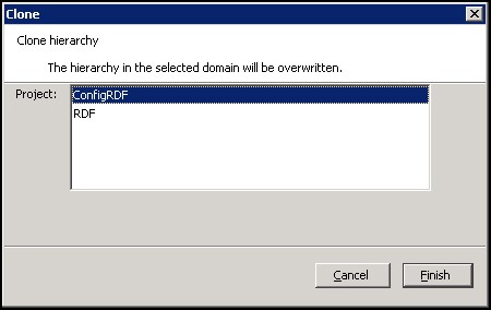
The RPASCE Configuration Tools allows for the hierarchies of an existing project to be copied into a new or existing project.
Complete the following steps to copy (clone) hierarchies.
Navigate: In the Configuration Components pane, select Project and then Hierarchies. The Figure 3-15 opens in the workspace.
-
Right-click Hierarchies in the Configuration Components pane and select Copy. The Figure 3-18 opens.
-
Select the destination project for the hierarchies to be copied.
-
Click Finish. The hierarchies in the selected project are overwritten.
Note:
Each project has a single set of hierarchies. Hierarchies can only be copied from one project to another, thus multiple projects must be open in the RPASCE Configuration Tools before the copy process is initiated.
Working with Position Formats
The Position Format is the date/time format used for the names of positions in the root dimension of the CLND (Calendar) hierarchy (typically day). Positions in the root dimension of the CLND hierarchy need names in a special format for RPAS CE to map abstract positions to actual dates and times in order to support time-aware calculations.
Note:
See Appendix – Calculation Engine User Guide and Appendix – Rules Function Reference Guide for more information.
Specifying the Position Format
Navigate: In the Configuration Components pane, select Project and then Hierarchies. The Figure 3-15 opens in the workspace.
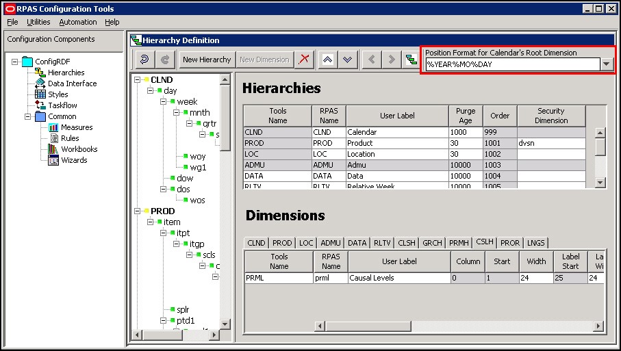
Figure 3-19 Example of Position Format in Hierarchy Definition Window
Description of "Figure 3-19 Example of Position Format in Hierarchy Definition Window"
The Figure 3-20 is located in the upper right-hand side of the Hierarchy Definition toolbar.
This is a combo box that is populated with some of the more commonly used formats. However, the configuration administrator may also type directly in the combo box if a different format is desired.
Specify the position format as a concatenated sequence of strings and arguments using the appropriate syntax. Refer to Position Format Syntax for more information.
Position Format Syntax
The Position Format field uses the following syntax conventions:
-
%YEAR – Four-digit Gregorian calendar year.
-
%YR – Two east significant digits of the year (for example, 15 is 2015).
-
%MO – Two-digit representation of month (for example, 01 is January).
-
%MON – Three-character abbreviation of the month name.
-
%MONTH – Varying length full name of the month, displays up to nine characters.
Note:
Even when configuring a solution in another language, RPASCE expects the month names and abbreviations (%MONTH and %MON) used in the position names to be in English (for example, Jan, Feb, Mar, and so on).
-
%DAY – Two-digit representation of the day of the month (for example, 01 is the first day of the month)
-
%HR – Two-digit representation of the hour of the day (for example, 22 is 10 p.m.).
-
%MIN – Two-digit representation of minutes past the hour.
-
%SEC – Two-digit representation of seconds past the current minute.
-
%MSEC – Three-digit milliseconds past the current second.
The Position Format is not case sensitive, so %YEAR is the same as %year.
The length of the position name must not exceed 24 characters. The Position Format field performs validation on the Position Format in order to enforce this limitation. For example, the Position Format %YEAR%MONTH%DAY evaluates to a total of 15 characters (4 for the year, 9 for month, and 2 for day).
Examples:
-
Format: %YEAR%MO%DAY
-
A position that represents the January 31, 2013 would have the name 20130131
-
Format: %YR%MON%DAY
-
A position that represents the January 31, 2013 would have the name 13Jan31
Working with Dimensions
Dimensions are the components within a hierarchy that define the structure and roll up within a hierarchy. For example, the dimensions for a calendar hierarchy can be day, week, month, and year, or they can be accounting periods.
Create a Dimension
Complete the following steps to create a dimension.
Navigate: In the Configuration Components pane, select Project and then Hierarchies. The Figure 3-15 opens in the workspace.
-
Select the hierarchy or dimension under which to create the new dimension.
Note:
When this guide uses terms like top and bottom level dimensions or over and under, these terms are to be interpreted visually. The bottom level is at the top of the hierarchy, and the top levels are at the end of the hierarchy branches. For example, the top dimension visually is the root dimension, which is the lowest dimension in the hierarchy. The highest dimensions in the hierarchy are at the bottom end of the hierarchy branches. For instance, Day is the bottom level of a Calendar hierarchy, but it falls directly beneath CLND.
-
Choose one of the following methods:
-
From the Hierarchy Definition right-click menu, select New Dimension.
-
Click New Dimension from the toolbar.
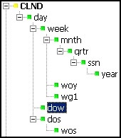
Create the first dimension, which becomes the root dimension, for a new hierarchy when positioned on the hierarchy. Once the root dimension is defined, new dimensions cannot be defined directly under the hierarchy. New dimensions are added under other dimensions. For example, after "Day" is added to the CLND hierarchy, CLND cannot be selected again to add "Hour." However, "Week" can be added under the "Day" dimension. There can only be one root dimension created per hierarchy.
Note:
Certain processes that support the purging of data or positions and the mapping of real dates/times to positions require a dimension in the CLND hierarchy that is named "day" and represents the day level. Such a dimension must be defined, although the user label can be changed from "day" if needed for localization purposes.
There is no limit on the number of dimensions that may be created for a hierarchy.
-
-
Define the dimension as necessary. Refer to "Defining Dimension Properties" for more information.
Defining Dimension Properties
Complete the following steps to define the dimension properties.
Navigate: In the Configuration Components pane, select Project and then Hierarchies.
-
Select a dimension using one of the following methods:
-
From the Hierarchy tree, select the dimension you want to modify.
-
From the Dimensions region of the Hierarchy Definition window, select the hierarchy tab that contains the dimension you want to define or modify.
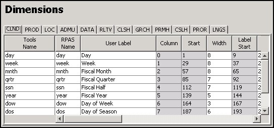
Figure 3-21 First Half of the Dimensions Properties Window PROD Tab Selected
Description of "Figure 3-21 First Half of the Dimensions Properties Window PROD Tab Selected"Figure 3-22 Second Half of the Dimensions Properties Window PROD Tab Selected

Description of "Figure 3-22 Second Half of the Dimensions Properties Window PROD Tab Selected"Figure 3-23 First Half of the Dimensions Property Window PROR Tab Selected
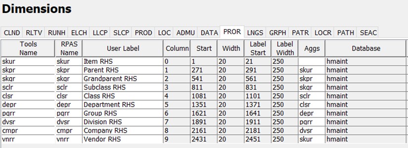
Description of "Figure 3-23 First Half of the Dimensions Property Window PROR Tab Selected"Figure 3-24 Second Half of the Dimension Properties Window PROR Tab Selected

Description of "Figure 3-24 Second Half of the Dimension Properties Window PROR Tab Selected" -
-
In the Dimensions properties region, select or double-click in the field to edit. Scroll to the right to see all of the fields. You can resize the columns by placing the cursor over the column until the double-sided arrow displays and then drag the column to the desired width.
Other than the RPAS name, the columns can be reordered by dragging and dropping the headings. The column positions will return to the default order when the session is closed.
You can specify the following dimension information:
Note:
Only four of the dimension properties are patchable in an existing PDS. Once the PDS is built, changes made to any other dimension properties are ignored.
If a dimension's property is patchable, it stated in a note in its description listed in Dimension Properties Descriptions.
Dimension Properties Descriptions
Tools Name
The name of the dimension that is displayed within the RPASCE Configuration Tools. This field allows you to assign meaningful labels while working with a configuration in the Configuration Tools. For example, the Tools Name displays in Select Intersection window, making it easier for you to assign the appropriate intersections.
RPAS Name
The RPAS internal name of the dimension. This dimension name is used only by RPASCE (not the user) within the application.
User Label
The dimension description that is displayed to RPASCE users in the RPASCE Client.
Note:
Any alpha-numeric characters are allowed. Single or double quotes are not allowed.
Column
Identifies the order in which the dimension's positions fall in the meta-data load file. Use the left and right arrow buttons to change the order and the column value of the dimensions. Changing the column value will not affect the hierarchy structure or aggregation paths.
Note:
The up and down arrow buttons are used for defining the sequence of hierarchies.
Example:
Change the column values if the dimensions in the data load file are not in the same order as in the tree structure. Dimensions will be moved up or down in the table without impacting the aggregates.
Start
This is a read-only, calculated field. This field identifies the start position of the position names for this dimension in the hierarchy load file.
Width
This field identifies the width of position names for this dimension in the hierarchy load file.
Label Start
This is a read-only, calculated field. This field identifies the start position of the position label for this dimension in the hierarchy load file. The sum of the dimensions of the Start and Width fields determines the value of the Label Start.
Label Width
This field identifies the width of position labels for this dimension in the hierarchy load file.
Note:
When using comma separated value (CSV) files to load data into RPASCE, the following dimension are ignored: Column, Start, Width, Label Start, and Label Width. See the Oracle Retail Predictive Application Server Cloud Edition Administration Guide for more information on Comma Separated Value (CSV) flat file format data load and export.
Aggs
This field establishes the relationship of the dimension to the other dimensions in the same hierarchy. Specifically, this field references the child dimension that aggregates up to this dimension (the parent dimension). It can be edited by using the drop-down list, or you can drag and drop dimensions in the left-hand side hierarchy pane.
User Dimension
When selected (checked), this field indicates that the dimension is user maintained. User-defined definitions (UDD) cannot have another dimension as a parent. Positions and position mappings (parent-child relationships) for user-defined dimensions are established in the RPASCE Administrative workbook template, “Hierarchy Maintenance." This meta-data cannot be loaded like regular (non-user-defined) dimensions in the hierarchy load process. A DPM-enabled dimension cannot be set to User Dimension and vice versa.
Translate
When selected, this field enables the position labels for the dimension to be translated into multiple languages. Positions are loaded into the PDS in the native language of the PDS via the standard hierarchy load process. Position labels for additional languages are loaded into special measures that are used in this multi-lingual PDS. With the proper setup, these translated position labels can be displayed in workbooks in the RPASCE Client instead of the loaded position labels. See the Oracle Retail Predictive Application Server Cloud Edition Administration Guide for detailed instructions for enabling position label translation.
Note:
The PDS is always built as multi-lingual. Enabling the translation of a dimension is patchable and does not adversely affect the expected results if altered. However, disabling translation is not patchable and may result in failure.
Cardinality
Use this field to specify the approximate size of a dimension in terms of the number of positions the dimension is expected to contain. Based on the range you select, RPASCE allocates a number of bits within its internal representation of the dimension and all measures that contain that dimension in their intersection. This ability to configure the amount of space necessary to represent the positions of a dimension will result in smaller PDSs. The range options are:
-
Very small: between 1 and 100 positions (8 bits)
-
Small: between 100 and 800 positions (10 bits)
-
Medium: between 800 and 12,000 positions (14 bits)
-
Large: between 12,000 and 100,000 positions (17 bits)
-
Very Large: between 100,000 and 500,000 positions (20 bits)
-
Extremely Large: between 500,000 and 2,000,000 positions (22 bits)
-
Ultra Large: between 2,000,000 and 4,000,000 positions (23 bits)
-
Custom: selecting this option allows you to enter a specify bit number. An input window opens. Enter the bit number and click OK.
Figure 3-25 Input Window for Custom Cardinality Option
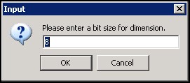
Description of "Figure 3-25 Input Window for Custom Cardinality Option"
Note:
The cardinality property of a dimension is patchable.
Enable DPM
Dynamic Position Maintenance (DPM) allows informal positions to be added to a dimension on-the-fly from the RPASCE Client. Select the Enable DPM option for the dimensions that will be enabled to support DPM. After Enable DPM is defined for the dimension, you must also specify workbooks and the dimensions in each workbook that will use DPM (see the Workbook Designer window for more details). A user defined dimension cannot be enabled to support DPM, and vice versa.
Note:
DPM can be enabled for all hierarchy dimensions except for CLND, ADMU, and LNGS.
When Enable DPM is selected for a specified dimension, it is also selected for all dimensions that roll up to it.
For more information on managing DPM positions using the Online Administration Tasks templates, see the Oracle Retail Predictive Application Server Administration Guide.
For more information on working with DPM positions in a workbook instance, see Oracle Retail Predictive Application Server User Guide.
Enabling DPM is patchable and will not adversely affect the expected results if altered. However, disabling DPM is not patchable. DPM may be unavailable for the templates, but not for the dimension.
DPM positions are application specific. Positions that are created in a specific application are visible only to the application. These positions will continue to be exclusive to the application until they are formalized. They are not controlled by the Position Visibility Filter and the application cannot hide these positions by using the PVF. Only after these positions are formalized, will their visibility to the application be determined by the Position Visibility Filter settings.
Enable Images
Select this option to enable the association of images (image paths) to positions along the specified dimension. To disable this feature, clear the option for the appropriate dimensions. This option is available for all hierarchy dimensions, except the calendar hierarchy. For the calendar hierarchy, the Enable Images column is unavailable or grayed. RPASCE supports GIF, BMP, and JPEG image formats. Once Enable Images is defined for a dimension, you must also specify the workbook that will use this feature (see the Workbook Designer window for more details). This is the legacy functionality for displaying images in the application. It is still supported for backward compatibility; however, the new preferred way for displaying images is using a dimension attribute measure of type string with the UI Type property set to media. For more information, see "Images and Contextual Help" in Oracle Retail Predictive Application Server Cloud Edition Administration Guide.
Note:
Enabling and disabling images is patchable and will not adversely affect the expected results if altered.
Attribute Measure
Attribute Measure is used to support dimension attributes and store dimension attribute values for the current dimension. See the Oracle Retail Predictive Application Server Cloud Edition Administration Guide and Oracle Retail Predictive Application Server Cloud Edition User Guide for more information on Attribute Measure.
Attribute Measure is available for selection if the hierarchy of the current dimension has Attribute Hierarchy defined and qualified measures exist in the application. The candidate measures must meet the following criteria: String type, have storage database in the application, 2-D measure with the base intersection at current dimension and the attribute name dimension. The user can select, at most, one attribute measure from the drop-down list. The selected measure is displayed in the Attribute Measure field.
In the following example, the Prod hierarchy has the attribute hierarchy PATH configured with the attribute value dimension. PATV rolls up to the attribute name dimension PATN. Suppose the PATV dimension has position Blue, Red, Green, Brand1, Brand2, Brand,3 and the PATN dimension has the position color and brand. The PATV positions Blue, Red, and Green roll up to the PATN position color, and
Brand1, Brand2, and Brand3 roll up to the PATN position brand. Then the Sku dimension has the qualified measure skuattrval1 available for selection.
Figure 3-26 The Example Content of the Attribute Measure skuattrval1
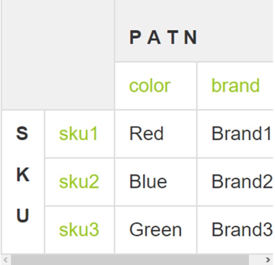
Description of "Figure 3-26 The Example Content of the Attribute Measure skuattrval1"
Figure 3-27 The Dimensions Properties Table Showing Attribute Measure Field
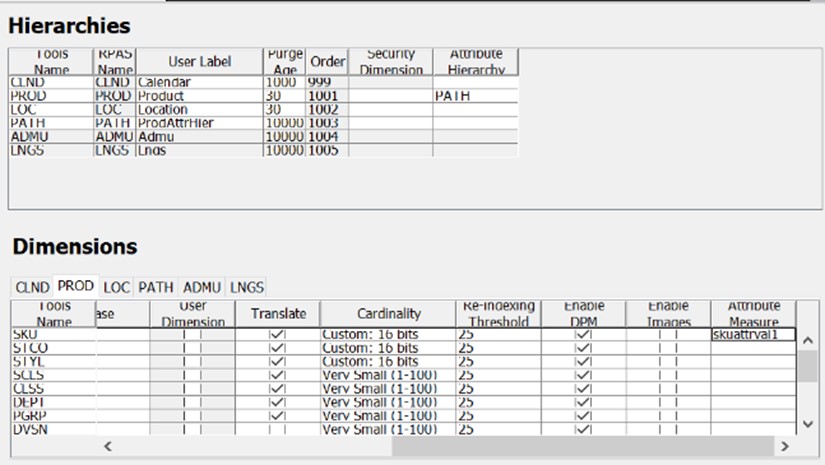
Description of "Figure 3-27 The Dimensions Properties Table Showing Attribute Measure Field"
The Dimensions Properties Table Showing Attribute Measure Field
Note:
If the attribute measure setting is changed between configurations, the existing PDS must be patched with the new configuration to sync up the RPASCE metadata.
Virtual Dimension
Select a dimension from the drop-down list to enable the association of the virtual dimension with its original dimension. The drop-down list is only enabled if a virtual hierarchy has been specified for this hierarchy in the Hierarchies table. Only then is the drop-down list pre-populated with all the dimensions from the virtual hierarchy. The user can select only one dimension from the drop-down list as the virtual dimension for this dimension. If this field is left blank, then this dimension has no virtual dimension.
The following dimension properties cannot be set for the virtual dimension since the virtual dimension will inherit them from its original dimension: Column, start, width, Label Start, Label Width, Database, Cardinality, Re-indexing Threshold, and Translate.
The following dimension properties cannot be set for the virtual dimension because they do not apply to virtual dimensions: User Dimension and Enable DPM, Virtual Dimension. Virtual dimensions cannot be user-defined dimensions and DPM-enabled.
Note:
The Virtual dimension can be changed and patched in the RPASCE application, but the user must be careful when changing them. The change to the virtual dimension must be consistent with the virtual hierarchy setting.
If a hierarchy is set to virtual, then all its containing dimensions must be set to virtual dimensions and the topology (such as dimension roll up relationship and so on) of the virtual hierarchy must match the original hierarchy.
Delete a Dimension
Complete the following steps to delete a dimension.
Navigate: In the Configuration Components pane, select Project and then Hierarchies. The Hierarchy Definition window opens in the workspace.
-
From the Dimensions region or from the Hierarchy navigation tree, select the dimension to be deleted.
-
Complete one of the following options:
-
Click the Delete icon.
-
Click Delete.
-
Select Delete from the right-click menu in navigating in the Hierarchy navigation tree.
-
Note:
Deleting a dimension causes all of the dimensions that are structurally dependant on it (its parents, grandparents, and so on) to also be deleted.
Note:
The user dimension contained in the ADMU hierarchy cannot be deleted.
Edit a Dimension
Complete the following steps to edit a dimension.
Navigate: In the Configuration Manager, select Project and then Hierarchies. The Hierarchy Definition window opens in the workspace.
-
Select the Hierarchy in which a dimension is to be edited.
-
From the Dimensions region, select the dimension to edit.
-
Update the dimension property as necessary. Refer to Defining Dimension Properties for more information about updating the dimension property.
-
To change the order of the dimension, click the left or right buttons to change the order of the dimensions. Re-ordering dimensions only affects the file, not the parent-child relationship of data.
Note:
The up and down arrows are used to change the order of hierarchies only.
Create a Branch in a Hierarchy
Complete the following steps to create a branch in a hierarchy.
Navigate: In the Configuration Components pane, select Project and then Hierarchies. The Hierarchy Definition window opens in the workspace.
-
From the Dimensions region or from the hierarchy navigation tree, select the dimension that will be the base of the branched hierarchy. The base of the branched hierarchy is the root dimension.
Note:
Ensure that the root dimension will have more than one parent (that is, where the branch starts), and create another parent dimension. Branches can never join together (for example, both style-subclass-class and style-supplier-class roll-ups in the same hierarchy are invalid).
-
Choose one of the following methods:
-
From the Hierarchy Definition right-click menu, select New Dimension.
-
Click New Dimension on the toolbar.
-
Press Insert.
The new dimension is created underneath the selected dimension.
-
Labeled Intersections
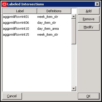
The Labeled Intersections window supports the addition, removal and modification of hierarchy intersections. A hierarchy intersection defines the dimensionality at which data is defined. An intersection may be defined as using no dimension (scalar), using a single dimension from a hierarchy, or multiple dimensions from different hierarchies.
Note:
See the section Measure Definition and Base Intersections for more information on defining intersections for data.
Navigate: In the Configuration Components pane, select Project and then Hierarchies. The Hierarchy Definition window opens in the workspace.
From the Hierarchy Definition toolbar, select the Labeled Intersection icon. The Labeled Intersections window opens. This window allows you to add new intersections or remove or modify existing intersections.
Adding a Labeled Intersection
Complete the following steps to add a labeled intersection.
-
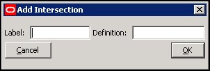
Click Add from the Labeled Intersection window. The Add Intersection window opens.
-
Complete the following:
-
In the Label field, enter a label for the Labeled Intersection.
-
In the Definition field, enter the dimension names for the intersection.
-
Click OK. The window closes, and the new entry displays in the Labeled Intersection window.
Note:
If the Definition field is left empty, the measure is assumed to be Scalar. If the level is non-scalar, dimension names are used to define the intersection. If multiple dimension names are to be specified, each dimension name must be separated by an underscore (_). The last dimension specified should not have an underscore following the dimension name. As well, there is no required order of dimensions.
Figure 3-31 Example of New Labeled Intersections
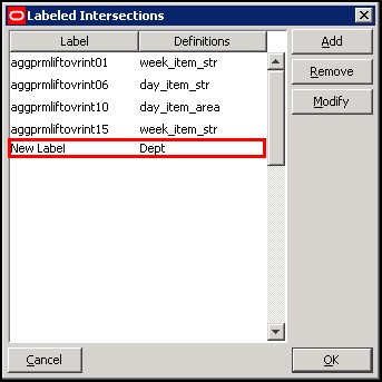
Description of "Figure 3-31 Example of New Labeled Intersections" -
-
Click OK.
-
Once the labeled intersection is added, you can complete the following:
-
Define or update the Base Intersection of major or minor measure component using the labeled intersection.
-
Define or update the Load Intersection of a measure using the labeled intersection.
-
Define or update the Base Intersection of a worksheet using the labeled intersection.
-
Note:
RPASCE imposes a limit of five dimensions that can be defined in a measure or worksheet's base intersection.
Modifying a Labeled Intersection
Complete the following steps to modify a labeled intersection.
-
Select a labeled intersection.
-
Click Modify from the Labeled Intersection menu.
-
Only the Definition field can be modified.
Click OK. If the change is undesired, click Cancel.
When the Definition of an existing labeled intersection is modified, the base intersections of measures and worksheets, and load intersections of measures that are currently assigned the labeled intersection are automatically updated. No action is required.
Removing a Labeled Intersection
Complete the following steps to remove a labeled intersection.
-
Select a labeled intersection.
-
Click Remove from the Labeled Intersection window.
-
Click OK.
When an existing labeled intersection is removed, the base intersections of measures and worksheets, and load intersections of measures that are currently assigned the labeled intersection will be displayed as invalid (red). Warning messages also display in the Task List, indicating the intersections that must be updated. These intersections must be corrected prior to installing or patching a PDS instance.
Configure 2-Dimensional Dimension Attribute
Users can use the combination of Attribute Hierarchy and Attribute Measure to configure 2-dimensional dimension attributes. The 2-dimensional dimension attribute does not replace the static 1-dimensional dimension attribute using 1-dimensional measures. The dimension attributes defined using Attribute Hierarchy can only handle String type measures. The 2-dimensional dimension attribute is a complement, rather than a replacement, of the static 1-dimensional dimension attribute.
Define Attribute Hierarchy and Attribute Measure
To configure 2-dimensional attributes, first, users must configure the attribute hierarchy and attribute measure. See the previous Attribute Hierarchy and Attribute Measure sections for details. Using the examples there, users must configure PATH as the attribute hierarchy for PROD (Product) hierarchy and measure skuattrval1 as the attribute measure for SKU dimension.
The hierarchy PATH contains the PATN and PATV dimensions with PATV rolling up to PATN. New attributes such as Color and Brand are positions along the PATN dimension, and new attribute values such as red, blue, green, brand1, brand2, and brand3 are positions along the PATV dimension.
Add Dimension Attribute Positions
Second, the new attribute name and attribute value positions must be loaded into the application. Within Attribute Hierarchy, the new dimension attributes are simply the new positions on the attribute name dimension. In other words, the new attribute and all its valid positions and child positions must be provided in the attribute hierarchy load file. Usually, the loadHier call is used to add the attribute.
Enable Dimension Attribute
Third, after the dimension attribute positions are loaded into the PDS, the new attributes for the particular dimension must be enabled. As in the previous example, valid values have been loaded into the application’s PATN and PATV dimensions. Now users must enable the Color and Brand attributes for the SKU dimension. This is achieved by running the following commands in the PDS’s root directory:
dattrmgr -d . -register skuattrval1 -dattname color
dattrmgr -d . -register skuattrval1 -dattname brand
The measure name skuattrval1 must match the one
specified as the attrmeas property for the SKU dimension,
and the dattname must be the attribute name in the PATN dimension.
Note:
The 2-dimensional dimension attributes do not support dynamic dimension attributes that are dimension attributes defined on a slice of the multi-dimension measure array. A dynamic dimension attribute requires its own infrastructure to store the slicing information and depends on the 1-dimensional dimension attribute infrastructure.
Data Interface Manager
The Data Interface Manager tool is used to specify information about how data will be loaded into the Planning Data Schema (PDS) using flat files. This includes properties of the file to be loaded and the intersection at which data is loaded into the PDS.
Data can only be loaded into stored, realized measures in the PDS. Therefore, only such measures can be used in the Data Interface Manager. One such measure may correspond to one fact within the PDS, or multiple measures from multiple applications can use the same fact to store the data. Refer to Shared Measure and Working with Measures section of this guide.
In the Data Interface manager table, the measures are displayed in alphabetic order. The user can sort table row by column. The sorting is case-insensitive.
Shared Measure
In the PDS, one shared fact can be used to store data from multiple measures from multiple applications. For example, one measure from IPOCS-Demand Forecasting and one measure from MFP both use the same fact in the PDS to store data. These measures are called shared measures. Shared measures of the same shared fact do not always have the same measure name and same measure base intersection. The base intersections of shared measures can be different because each application may use them at different levels.
Users configure shared measures inside the Data Interface Manager by specifying the Shared Fact Name and Shared Fact Base Intersection. Measures that do not have the Shared Fact Name configured are non-shared measures, that is, they do not share data with measures from other applications.
In this way, even when the PDS instance is initially generated with only one application, the fact table of shared measures are created at the expected intersection. For example, a PDS instance is initially created with MFPRCS, which has shared measure at SCLS base level. However, they are expected to be shared with measures defined at SKU base level in other applications. Users can explicitly set the shared fact intersection at SKU for shared measures, and the fact table will be created at SKU correctly. When a new application such as ASCS or IPOCS-Demand Forecasting that uses the shared measure at SKU is added later, the fact table is valid and no data loss will occur.
Assumptions for Shared Measures
-
Shared Measures must have the common fact name provided by the configurator.
-
Shared Measures can have at most two different base intersections. Their base intersections must be at or higher than the fact intersection, but can only be higher at one base dimension. For example, if the shared measure’s base intersection is week_scls_dstr while the fact intersection is week_sku_stor, this is an invalid configuration.
-
Shared measures must have the same measure navalue, defagg, defspread, and purgeage properties.
-
For the same shared fact, one application cannot have more than one measure mapped to it.
-
If no shared fact intersection is specified, then the shared measures must have the same base intersection. Their base intersection is used as the fact intersection.
-
For shared measures, labels are application-specific.
-
Shared measures must be loaded.
-
The shared measure fact intersection must adhere to the criteria for Shared Fact Intersection listed in the later section.
Specify the Data Interface for a Measure
Complete the following steps to specify the data interface for a measure.
Navigate: In the Configuration Components pane, select Project and then Data Interface. The Data Interface Manager window opens in the workspace.
Figure 3-32 Example of Data Interface Manager Window

Description of "Figure 3-32 Example of Data Interface Manager Window"
-
Click New Meas. The New Measure Specification window opens.
Figure 3-33 Example of New Measure Specification Window
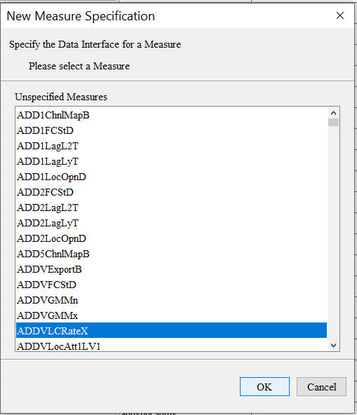
Note:
This is a filtered list of all possible measures in the configuration. Measures will be displayed in ascending alphabetic order in this list if they are realized, stored (has a defined database), and not already defined in the data interface tool.
-
Select the measure requiring a data interface definition.
-
Click OK. The measure displays in the Data Interface Manager window.
Add/Edit Data Interface Properties for a Measure
Complete the following steps to add and or edit data interface properties for a measure.
Navigate: In the Configuration Components pane, select Project and then Data Interface. The Data Interface Manager window opens in the workspace.
By default, the Load Intersection field is populated with the base intersection of the measure. If the data for a given measure is being loaded at a lower intersection than the base intersection of the measure, this value can be overridden to specify the intersection.
Note:
Data can be loaded at the same intersection or lower than the base intersection of a measure. Data cannot be loaded at a higher intersection than the base intersection. Measures are loaded into the PDS instance using CSV-formatted input files with a header using the utility loadFactData. The measure properties Start Position, Column Width, and Clear Intersection, no longer apply.
Figure 3-34 Data Interface Manager Window – Add/Edit

Description of "Figure 3-34 Data Interface Manager Window – Add/Edit"
-
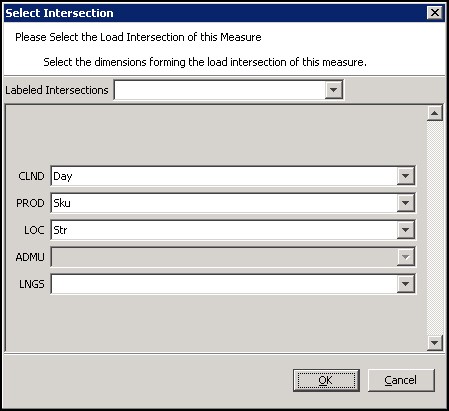
Click the Load Intersection field to change its value. The Select Intersection window opens.
-
To specify the load intersection:
-
Using the list options, select the appropriate dimensions or Labeled Intersection.
Note:
Only those dimensions that are at the same level as the base intersection or lower is displayed for the load intersection.
-
Click OK to save any changes and close the window.
-
-
In the File Name field, enter the file name from which data for the measure will be loaded. The File Name property is used in fact grouping algorithms. This is covered in detail in the Integration Tools chapter.
-
If the Load Intersection was overridden to specify that the data is to be loaded from an intersection lower than the measure's base intersection, the measure's default aggregation method is used to aggregate the data unless the Load Aggregate field is populated to specify an alternate aggregation method. Click the Load Aggregation Method field and select the appropriate aggregation method from the option list.
Note:
Hybrid is not supported for the load aggregation for a measure.
-
If the measure is a shared measure, enter the shared fact name into the Shared Fact Name field and the shared fact base intersection into the Shared Fact Base Intersection field. The explicit specification of the shared fact name is mandatory for shared measures. Measures that do not have the shared fact name configured are considered non-shared measures.
The shared fact name must not exceed 30 characters in length and must not contain spaces. It is recommended to follow measure naming conventions when configuring the Shared Fact field.
-
The specification of the shared fact intersection is optional. Both shared and non-shared measures can specify a value for the Shared Fact Intersection field. The explicitly specified value is used as the fact base intersection during integration configuration generation.; if not specified, the measure's base intersection is used as the fact intersection. . Refer to the Integration Tools chapter.
The shared measure fact intersection must adhere to the following criteria:-
Fact intx must be AT or below the shared measure's base intersection. For example, if the measure base intx is at DEPT, then the fact intx must be at either DEPT or below such as SKU.
-
If fact intx is below its measure's base intx, then the measure's base intx can neither be above the PDS partitioning dimension nor can have more than one aggregated dimensions.
For example, when the PDS partitioning dim is DEPT along PROD hierarchy,
Valid Cases:
Shared Fact Intx SKU STOR WEEK --> Measure Base Intx SCLS STOR WEEK
Shared Fact Intx SKU STOR WEEK --> Measure Base Intx CLSS STOR WEEK
Invalid Cases:
Shared Fact Intx SKU STOR WEEK --> Measure Base Intx PGRP STOR WEEK ( above partition level)
Shared Fact Intx SKU STOR WEEK --> Measure Base Intx CLR STOR WEEK (side branch and not directly below partition level)
Shared Fact Intx SKU STOR WEEK --> Measure Base Intx SKU WEEK (aggregate to top of non-partition dimension, mis-match dimensionality)
Shared Fact intx SKU STOR WEEK --> Measure Base Intx STYL DSTR WEEK (aggregate on more than one dimension)
Such invalid configuration will cause a validation error generated in the ConfigTools Tasklist Pane when the shared fact intersection is displayed in Data Interface Manager. If the user does not correct them, the PDS deploy or patching process will fail during the integration configuration generation.
When a measure’s base intersection is higher than the Shared Fact Intersection, the measure’s data must be loaded instead of being calculated or updated. If such measure is used on the Left-Hand-Side (LHS) of a batch expression or workbook commit rules, the PDS config generation will fail. As a result, the application deploy or patching will fail upon this invalid configuration. Such measures must not be used as LHS measures within any batch rule, workbook commit rules, or batch free expression in batch control files.
-
-
The Source Fact property is used to indicate which measure, that is, the corresponding fact, can be updated via the ORDS Put (write) service. Only the measures that have the Source Fact set to TRUE can have their corresponding facts updated by the ORDS Put web service. For any new measures added into the Data Interface Manager, the Source Fact field defaults to True since measures inside the Data Interface Manager are load measures. Users can explicitly make this measure invisible by clicking this field and selecting False from the drop-down list. More details on Planning Data Schema Default Web Services (through ORDS) can be found in the Oracle Retail Predictive Application Server Cloud Service Administration Guide.
Delete Data Interface Information for a Measure
Complete the following steps to delete data interface information for a measure.
Navigate: In the Configuration Components pane, select Project and then Data Interface. The Data Interface Manager window opens in the workspace.
-
Select the measure you want to remove from the Data Interface Manager.
-
Click Delete Meas.
-
Click Yes. The measure is removed from the table.
Working with Styles
It is possible for the RPASCE Client user to modify the appearance of the data displayed for a given measure in a grid. Text font, size, and color may all be changed. Many attributes, such as precision (for decimal data types), alignment of the value in the cell, and the cell border may also change.
Using the Style Tool, it is possible to define styles that may be applied to measures. These predefined styles may specify any of a body of attributes that determine the appearance of the data within the client. It is then possible to specify a measure as using one of these pre-defined styles. The measure will then be displayed according to the specifications for that style.
Note:
The RPASCE Client is not aware of styles which are a configuration convenience. In the client, the individual properties are maintained individually. A style can therefore be thought of as a mechanism to easily set many individual properties.
The Style Definition Tool
The Style Definition Tool provides the following functionality:
-
Allows the creation and management of named styles. New styles are generated as sub-styles of existing styles.
-
Allows the specification of the attributes of named styles. Style attributes follow an inheritance scheme in which any unspecified attribute will inherit a value from its parent style if that style has a specification.
-
Allows the specified styles to be visible to the Measure and Workbook Tools where measures are marked as using a style.
Style Attributes
A number of attributes may be specified for a style. These attributes will determine how the data for a measure that uses the style is displayed within the RPASCE Client. Style attributes follow an inheritance framework in which an attribute defined in one style is also defined for all of the children of that style unless a style is defined for a child. The attributes of a style that may be specified are as follows:
Name
The name of the style. This is used in the Measure and Workbook Tools to assign a style to a measure. Since styles are a configuration convenience, style names are not visible in the RPASCE Client.
Prefix
A cell value in the RPASCE Client will be prefixed with this string. For example, a prefix could be “$" to denote U.S. currency values. The prefix can be any character sequence but cannot exceed seven characters.
Suffix
A cell value in the RPASCE Client will be suffixed with this string. For example, a suffix could be “%" to denote that the value in the field is a percentage of something. The suffix can be any character sequence but cannot exceed seven characters.
Scale Factor
A cell value in the RPASCE Client could use a scale factor for display purposes. A value that is calculated as a fraction could be displayed as a percent by selecting the scale factor to be 0.01 (The UI divides by the scale factor).
For example, if the value in a cell is 0.5, the scale factor would have to be 0.01 for the cell to display 50.
The value entered in the field should be greater than zero.
Precision
Precision is the number of significant digits to be displayed in the cell of the RPASCE Client. If this number is set to 3, the client must always display 3 positions after the decimal. For example, the measure value is 1, with a Precision setting of 3; it will be displayed as 1.000. The value entered in the field should be greater than zero.
Separator
A cell value in the RPASCE Client could be formatted to have separators in the value. The separator and the format come from the regional settings on the computer. For example, when a separator is used, a value of 1000 would be displayed as 1,000 or 1.000. It can also be displayed in other formats depending on the regional settings.
Text Font
Deprecated.
Note:
Text font is not used by the RPASCE Client.
Text Style
Sets the display style of the text value in the RPASCE Client (Bold, Italic, and so on).
Text Size
Deprecated.
Note:
Text size is not used by the RPASCE Client.
Text Color
Sets the color of the cell values in the RPASCE Client.
Background
Sets the background color of the cells in the RPASCE Client.
Note:
In the RPASCE Client, the measure formatting background color for a measure takes priority over the ‘read/write' background color that can be set for the application. Therefore, the RPASCE Client ‘read/write' color will not be seen if styles are used through the Configuration Tools. If a specific read/write color is desired for all measures, set it as the background color of the default style, and do not override it for any other styles. On the other hand, the RPASCE Client ‘read only' background color takes priority over the measure formatting background color so that ‘protection processing' will be visible.
Alignment
Sets the alignment of values within the cells when viewed in the RPASCE Client (Left, Center, and Right
Border Style
Sets they style of border of cells. Border style determines the kind of borders (for example, single line, dotted line, and so on) and where the borders should be relative to the cell value (top, bottom, left, right, or any combination of these).
Note:
Border style is not used by the RPASCE Client.
Border Color
Sets the color of the border lines for cell values.
Note:
Border color is not used by the RPASCE Client.
Time Format
Sets the time format for styles. Options are No Time, Twenty-Four Hour, and Twelve Hour.
Create a Style
Complete the following steps to create a style.
Navigate: In the Configuration Components pane, select Project and then Styles. The Style Definition window opens in the workspace.
-
Select or create the Style that will be the parent of the new style. All styles must ultimately be descendents of the Default Style.
-
Choose one of the following methods:
-
From the toolbar, click Create a new style.
-
Select New Style from the right-click menu.
-
Press Insert.
If the Style Attributes for Default are populated, all of its descendants will inherit the same attributes unless you specify new attributes for the new styles. A new style will be created with inherited attribute values for all the properties set in its parent style.
The inherited style attribute values are displayed with lighter shade (gray) to differentiate from the un-inherited values (black). Notice that the style attributes for the style Default -are shown in black while the style attributes for the style Percent are in gray.
-
-
Change the values of any of the new style's attributes where a different value is required than that which has been inherited. For those attributes that have been overwritten from the “Default" value will be display in black while those that have not been changed will remain gray to indicate they are inherited.
Remove a Style
Complete the following steps to remove a style.
Navigate: In the Configuration Components pane, select Project and then Styles. The Style Definition window opens in the workspace.
-
Select the style to be removed.
-
Choose one of the following methods:
-
From the toolbar, click Delete Style
-
Select Remove from the right-click menu.
-
Press Delete.
The selected style and all of its child styles will be removed from the style description tool. Any measures using a deleted style will be displayed as invalid.
-
Edit a Style
Complete the following steps to edit a style.
Navigate: In the Configuration Components pane, select Project and then Styles. The Style Definition window opens in the workspace.
-
Select the style to be edited.
-
Select the property of the style to be edited. Depending on the property selected, one of the following is displayed:
-
a color chooser (for all color selection properties like font color, background color, and so on)
-
a window (for Borders)
-
a list (for alignment, font, and text style)
-
a free flow text cursor (for all other properties)
-
-
Make the selection and enter the value for the property.
If the edited value is changed to the same as its parent's value for an attribute, the value is automatically changed to inherit from the parent, and it is displayed as gray rather than black.
-
If the value is to be deleted (does not contain any value), select the property, and press Delete.
Working with Taskflows
The RPASCE Client provides a more flexible approach to user interaction with the workbooks configured for an RPASCE application. This flexibility allows users to focus less on the structural elements that make up the workbook configuration and more on the tasks that they use those structural elements to perform.
This flexibility is found in the RPASCE Client taskflow. The taskflow allows configurators to more closely describe and model their business practices within the client. Configurators can create taskflow elements (activity groups, activities, tasks, and steps) that can be associated with structural elements of the workbook configuration. These taskflow elements then provide a more intuitive and business practice-oriented view of the structural elements of the RPASCE application.
The activity group activity/task/step can be organized however the user wants. The task refers to a template and specific solution. Inside a Configuration Tools configuration, they all refer to the same solution. Names are all qualified by the Solution ID. A single solution taskflow can have multiple activity groups.
When creating an activity, the activity group name, label, and description can be specified. When the sandbox is built, the activities are combined into an activity group based on the specified activity group properties. Each task is specific to a workbook template and therefore a specific solution.
Figure 3-41 shows the activity, task and steps for Item Planning.
Figure 3-41 Activity, Task and Steps for Item Planning
Description of "Figure 3-41 Activity, Task and Steps for Item Planning"
Using the RPASCE Configuration Tool, you have the ability to create a customized activity taskflow for the RPASCE Client. This activity taskflow helps users of the RPASCE Client understand the tasks they must complete in order to meet their planning goals.
The RPASCE Configuration Tool works on a taskflow for a single solution (configuration). Everything within it will be qualified by Solution ID. Within the RPASCE platform, it is not possible to create a deployment of multiple solutions that share a single client instance. As such, the need for preparation of a multi-solution taskflow is negated.
Some RPASCE configured solutions are delivered with preconfigured taskflows. These preconfigured taskflows can be customized using the procedures in the following sections. Or, you can Create a Taskflow.
Here is an example of a taskflow in the RPASCE Client.
Figure 3-42 Taskflow within the RPASCE Client Task Module
Description of "Figure 3-42 Taskflow within the RPASCE Client Task Module"
Figure 3-43 Taskflow Within the RPASCE Client Task Module

Description of "Figure 3-43 Taskflow Within the RPASCE Client Task Module"
Table 3-2 describes the icons that appear with all the entries in the activity taskflow.
Table 3-2 Taskflow Icon Key for the Taskflow within the RPASCE Client Task Module
| Legend | Icon Name | Description |
|---|---|---|
|
A |
Activities |
These tabs represent the predefined activities of the application. |
|
B |
Tasks |
These are the individual tasks within the selected activity. |
|
C |
Steps |
These are the steps available in the selected task. |
|
D |
View Groups (Tabs) |
These are the view groups defined within the selected step. If a step contains configured tabs, each tab is represented by a view group. If a step does not contain configured tabs, a single view group corresponding to the step itself is present. |
Create a Taskflow
Complete the following steps to create a taskflow.
Navigate: In the Configuration Components pane, select Taskflow within the project for which you want to create a taskflow.
Figure 3-44 Taskflow Icon in the Configuration Components Pane
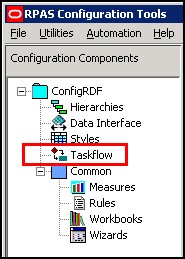
Description of "Figure 3-44 Taskflow Icon in the Configuration Components Pane"
The Taskflow Manager window opens. The first time that you use the Taskflow Manager, it contains one bullet called Taskflow.
Adding an Activity to the Taskflow
Complete the following steps to add an activity to the taskflow.
-
Select the Taskflow bullet inside the navigation pane of the Taskflow Manager. Click Add.
Figure 3-46 Adding an Activity to the Taskflow

Description of "Figure 3-46 Adding an Activity to the Taskflow" -
An activity called Activity1 displays in the navigation pane. Select Activity1. The Activity Properties displays in the detail pane.
-
Enter the name of the activity in the Label field. This is the name of the task as it displays in the taskflow of the RPASCE. The red asterisk denotes that this step is required. Note that as you type the name in the Label field, the name is updated in the navigation pane.
-
[Optional] Enter a description for the activity in the Description field. The description displays when the user rolls the cursor over the activity name in the RPASCE Client.
-
Enter the activity group name in the Activity Group Name field, group label in the Activity Group Label field, and group description in the Activity Group Description field. This step is optional. Note that the Activity Group Name must not contain any spaces. Otherwise, when the user clicks Validate, error messages will show up in the pop-up validation dialog box.
After you have entered the activity properties, the new activity is created.
Adding a Task to the Taskflow
Complete the following steps to add a task to the taskflow.
-
To create a task within an activity you created, select the activity in the navigation pane and click Add.
-
A task called Task1 displays in the navigation pane. Select Task1. The Task Properties display in the details pane.
-
Enter the following information in the Task Properties.
Label
Enter the name of the task as you want it to appear in the RPASCE Client. This step is required.
Description
Enter the description of the task. This description displays when the user rolls the cursor over the task name in the RPASCE Client.
Workbook Template
Choose the workbook template that will be utilized in this task. This step is required.
Show Unassigned Worksheets
By checking the unassigned flag, applications that include the potential for non-configured worksheets can allow those worksheets to be displayed within the RPASCE Client while continuing to maintain the ability to hide worksheets irrelevant to the task at hand for workbooks that do not contain non-configured worksheets.
Non-Authorized Users
Choose whether unauthorized users are able to see the task but are unable to edit it (Disable Task) or are not able to see it at all (Hide Task).
Once you've entered the task properties, the new task is created.
Dynamic Task is no longer supported in RPASCE.
Add a Step to the Taskflow
Complete the following steps to add a step to the taskflow.
-
To add a step to a task you created, select the task and click Add.
-
A step called Step1 displays in the navigation pane. Select Step1. The Step Properties display in the details pane.
-
Enter the following information in the details pane:
Label
Enter the name of the step as you want it to appear in the RPASCE Client. This is required.
Description
Enter the description of the step. This description displays when the user rolls the cursor over the step name in the RPASCE Client.
Worksheets
Select the worksheets that will be utilized in this step. You can select all worksheets to be included by checking the All check box. Alternatively, you can select a subset of worksheets from that workbook template. This is required.
Custom Menu
If you want to include a custom menu in this step, select it in the Available area and then use the arrow to move it to the Selected area. You can change the order of the custom steps by using the up and down arrows.
Once you have entered the step properties, the new step is created.
Add a Tab to the Taskflow
Complete the following steps to add a tab to the taskflow.
-
To add a tab to a step you created, select the step and click Add.
-
A tab called Tab1 displays in the navigation pane. Select Tab1. The Tab Properties displays in the details pane.
-
Enter the following information for the tab:
Label
Enter the name of the tab as you want it to appear in the RPASCE Client. This is required.
Worksheets
Select the worksheets that will be utilized in this tab. You can select all worksheets to be included by checking the All check box. Alternatively, you can select a subset of worksheets. This is required.
Once you have entered the tab properties, the new tab is created.
Delete Items from the Taskflow
Complete the following step to delete items from the taskflow.
-
To delete any activity, task, step, or tab in the taskflow, select it and click Delete.
Figure 3-56 Deleting Items in the Taskflow
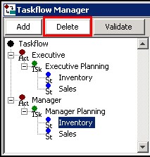
Description of "Figure 3-56 Deleting Items in the Taskflow"
Edit Items from the Taskflow
To edit an activity, task, step, or tab that you have already created, select it in the navigation pane. Its properties display in the details pane. Then edit the properties you want.
Order Items in the Taskflow
To change the order of activities, tasks, steps, or tabs, select the item that you want to move and use the arrow buttons to the right of the navigation pane. Click a single arrow to move it one level in the list. Click the double arrow to move it to the top or bottom of the list.
Figure 3-57 Ordering Items in the Taskflow
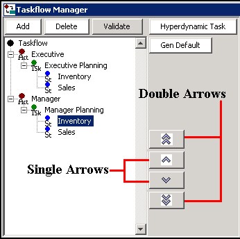
Description of "Figure 3-57 Ordering Items in the Taskflow"
Validate the Taskflow
As you create the taskflow, the Task List underneath the Taskflow Manager displays configuration elements that may cause validation errors. In addition, the Validation Results tool shows you if you have configured elements that are unavailable to users. For instance, if a configured taskflow does not have a task associated with a given workbook template, then the RPASCE Client user is not able to build or open any workbooks built from that template.
Note:
The presence of validation problems does not prevent you from building the PDSBase.
To validate your taskflow, click Validate at any time. The Validation Results window opens. The Validation Results tool checks for the following:
-
Workbook templates that are not associated with a task
-
Worksheets that are not a part of any step
-
Custom menu items that are not available in any step
-
Activity Group names that contain any spaces.
When conditions such as these exist, they display in the Validation Results window. Once you have reviewed the results, you can choose to resolve any issues if necessary.
The RPASCE Configuration Tools also performs validation within the Task List underneath the Taskflow Manager. As you edit within the Taskflow Manager, the Task List reports potential issues and errors within the configuration. For more information, see the Task List section.
Generate Default Mapping
Click Gen Default at any time to revert the taskflow to the default mapping.
The default mapping provides a basic structure to taskflow elements and can serve as either a simple configuration of workbook elements or as a starting point for a customized configuration of the taskflow elements.
The default mapping is set up as follows:
-
There is one activity generated for every workbook group in the application. The label of the workbook group is used as the activity's label and description.
-
Each activity contains a single task for each workbook present in the workbook group associated with that activity. The label of that workbook is used as the task's label and description. By default, workbooks are unavailable for unauthorized users in all tasks.
-
Each task contains a single step for each workbook tab present in the workbook associated with that task. The label of the worksheet is used as the step's label, description, and instructions. Each step includes the worksheets contained within the workbook tab associated with that step and does not include worksheets contained within other workbook tabs present in the workbook. Each step contains all Custom Menus present in the workbook.
-
The default mapping contains no taskflow tab elements.
Creating the Taskflow for a Taskflow Created in a Release Earlier than 13.3.1
If you have a taskflow created in a release earlier than 13.3.1 that you want to use in 14.0 or later (without running through ConfigTools for some reason), at minimum you need to do the following:
Add a single <activity_group> around the existing <activity> tags to group them.
Add a <solution> tag with the solution ID to each task in the taskflow.
Add resources to the property file for the new activity group, for example:
solution1.ActivityGroup1=sample activity group label
solution1.ActivityGroup1.Desc=sample activity group description
Add a resource to the property file for the solution's label:
solution1.Solution.label=sample solution label
You need to qualify all <name> and <description> IDs by putting the solutionId. in front of them. Then do the same in the properties file so they match up.
Upgrading retailers may have multiple taskflows on the same server, where the users who switch between them use profiles. In this case, you probably want to construct a multi-solution taskflow that includes each solution. The simplest way to do this is to combine taskflows from Configuration Tools or construct as previously noted by putting each <activity_group> in the multi-solution taskflow xml, one after another, and then concatenating all the .properties resource files.
Note:
The name of the activity group (for example, the ActivityGroup1 in above) must not contain spaces. Otherwise, the taskflow will not display correctly in the RPASCE UI.
