Install the Cable Management Arm (Optional)
Follow this procedure to install the cable management arm (CMA), which you can use to manage cables connected to the back of the storage server.
Note - Before you install the CMA, ensure that the right-angle AC power cables are long enough to connect to the rackmounted servers when routed through the CMA.
-
Unpack the CMA, which contains the following components.
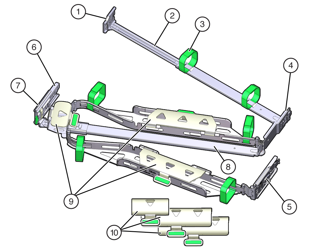 Call OutDescription1Connector A2Front slide bar3Velcro straps (6)4Connector B5Connector C6Connector D7Slide-rail latching bracket (used with connector D)8Back slide bar9Oracle Storage Server X7-2 (1U) flat cable covers10Oracle Storage Server X7-2L (2U) round cable covers
 -
Remove the flat cable covers and install the round cable covers.
-
Lift up on the cable cover handle (the handle is colored green)
and open it 180 degrees to the horizontal position as shown in the
following figure [frames 1 and 2].
Note - The CMA has three cable covers, two with two hinges (one of which is shown in the following figure), and one with a single hinge. All three cable covers are shown in the previous figure.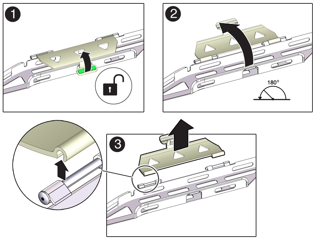
- Apply upward pressure to the outside edge of each hinge connector until the hinge connector comes off the hinge [frame 3].
- Repeat Step 2.a and Step 2.b to remove all three cable covers.
- One at a time, position each round cable cover horizontally over the hinges, and align the hinge connectors with the hinges.
- Using your thumb, apply downward pressure on each hinge connector to snap the hinge connector into place.
- Swing the cable covers down and press down on the cable cover handle to lock them into the closed position.
-
Lift up on the cable cover handle (the handle is colored green)
and open it 180 degrees to the horizontal position as shown in the
following figure [frames 1 and 2].
-
Ensure that the six Velcro straps are threaded into the CMA as shown in
the CMA Components figure at the beginning of this procedure.
Note - Ensure that the two Velcro straps located on the front slide bar are threaded through the opening in the top of the slide bar. This prevents the Velcro straps from interfering with the expansion and contraction of the slide bar when the storage server is extended out of the rack and returned into the rack. - Extend the storage server approximately 13 cm (5 inches) out of the front of the rack.
-
Take the CMA to the back of the equipment rack, and ensure that you have
adequate room to work at the back of the storage server.
Note - References to “left” or “right” in this procedure assume that you are facing the back of the equipment rack.
Note - Throughout this installation procedure, support the CMA and do not allow it to hang under its own weight until it is secured at all four attachment points. -
To install the CMA connector A into the left slide-rail:
-
Insert CMA connector A into the front slot on the left slide-rail
until it locks into place with an audible click [frames 1 and
2].
The connector A tab (see callout 1) goes into the slide-rail front slot (callout 2).
-
Gently tug on the left side of the front slide bar to verify that
connector A is properly seated.
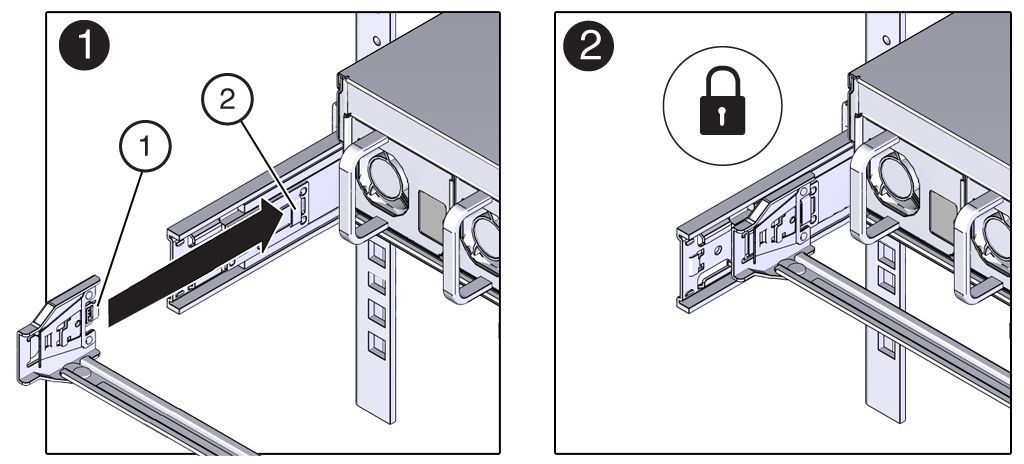 Call OutDescription1Connector A tab2Left slide-rail front slot
-
Insert CMA connector A into the front slot on the left slide-rail
until it locks into place with an audible click [frames 1 and
2].
-
To install CMA connector B into the right slide-rail:
-
Insert CMA connector B into the front slot on the right slide-rail
until it locks into place with an audible click [frames 1 and
2].
The connector B tab (see callout 1) goes into the slide-rail front slot (callout 2).
-
Gently tug on the right side of the front slide bar to verify that
connector B is properly seated.
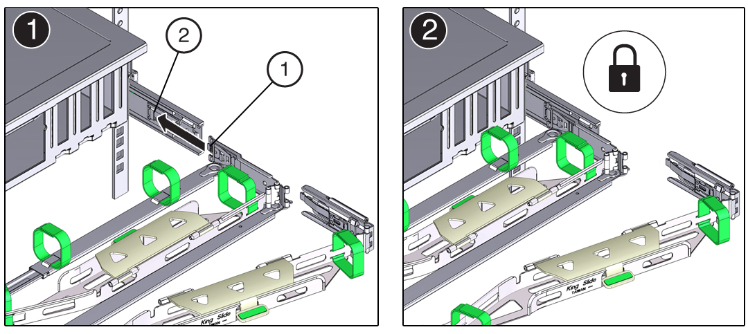 Call OutDescription1Connector B tab2Right slide-rail front slot
-
Insert CMA connector B into the front slot on the right slide-rail
until it locks into place with an audible click [frames 1 and
2].
-
To install CMA connector C into the right slide-rail:
-
Align connector C with the slide-rail so that the locking spring
(callout 1) is positioned inside (storage server side) of the right
slide-rail [frame 1].
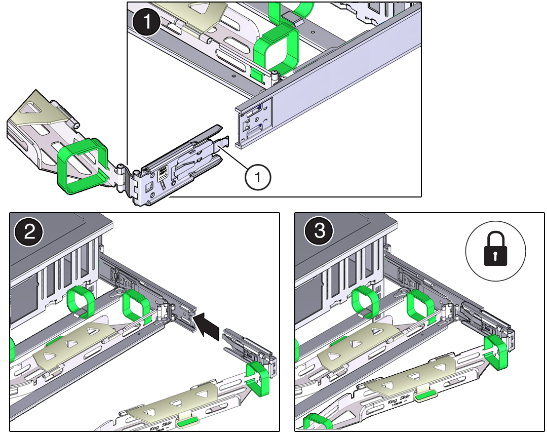 Call OutDescription1Connector C locking spring
 - Insert connector C into the right slide-rail until it locks into place with an audible click [frames 2 and 3].
- Gently tug on the right side of the CMA back slide bar to verify that connector C is properly seated.
-
Align connector C with the slide-rail so that the locking spring
(callout 1) is positioned inside (storage server side) of the right
slide-rail [frame 1].
-
To prepare CMA connector D for installation, remove the tape that secures
the slide-rail latching bracket to connector D and ensure that the latching
bracket is properly aligned with connector D [frames 1 and 2].
Note - The CMA is shipped with the slide-rail latching bracket taped to connector D. Remove the tape before you install this connector.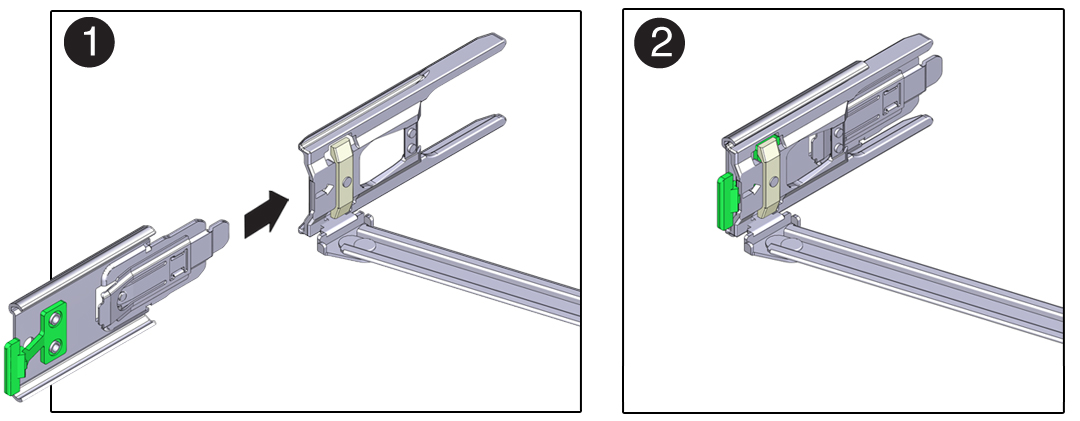
-
To install CMA connector D into the left slide-rail:
-
While holding the slide-rail latching bracket in place, insert
connector D and its associated slide-rail latching bracket into the
left slide-rail until connector D locks into place with an audible
click [frames 1 and 2].
Note - When inserting connector D into the slide-rail, the preferred and easier method is to install connector D and the latching bracket as one assembly into the slide-rail. -
Gently tug on the left side of the CMA slide bar to verify that
connector D is properly seated.
Note - The slide-rail latching bracket has a green release tab. Use this tab to release and remove the latching bracket so that you can remove connector D.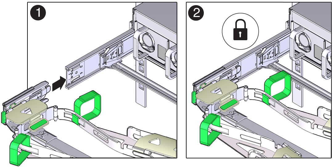
-
While holding the slide-rail latching bracket in place, insert
connector D and its associated slide-rail latching bracket into the
left slide-rail until connector D locks into place with an audible
click [frames 1 and 2].
- Gently tug on the four CMA connection points to ensure that the CMA connectors are fully seated before you allow the CMA to hang by its own weight.
-
To verify that the slide-rails and the CMA are operating properly before
routing cables through the CMA:
-
Ensure that the rack anti-tilt bar is extended to prevent the rack
from tipping forward when the server is extended.

Caution - To reduce the risk of personal injury, stabilize the rack cabinet and extend the anti-tilt bar before extending the server from the rack. For instructions on stabilizing the rack, see Stabilize the Rack.
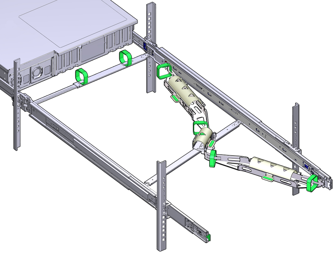
- Slowly pull the server out of the rack until the slide-rails reach their stops.
- Inspect the attached cables for any binding or kinks.
- Verify that the CMA extends fully with the slide-rails.
-
Ensure that the rack anti-tilt bar is extended to prevent the rack
from tipping forward when the server is extended.
-
To return the storage server to the rack:
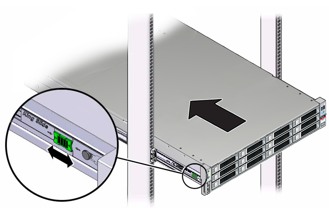
- Simultaneously pull and hold the two green release tabs (one on each side of the storage server) toward the front of the storage server while you push the storage server into the rack. As you push the storage server into the rack, verify that the CMA retracts without binding.
-
To pull the green release tabs, place your finger in the center of
each tab, not on the end, and apply pressure as you pull the tab
toward the front of the server.
-
Continue pushing the storage server into the rack until the
slide-rail locks (located on the front of the storage server) engage
the slide-rail assemblies.
You hear an audible click when the storage server is in the normal rack position.
-
Connect cables to the storage server, as required.
Instructions for connecting the storage server cables are provided in Cabling the Storage Server.
-
Open the CMA cable covers, route storage server cables through the CMA
cable troughs, close the cable covers, and secure the cables with the six
Velcro straps.
Route the cables through the cable troughs in this order:
- First through the front-most cable trough.
- Then through the small cable trough.
-
Then through the back-most cable trough

Caution - When securing the cables with the Velcro straps located on the front slide bar, ensure that the Velcro straps do not wrap around the bottom of the slide bar. Otherwise, expansion and contraction of the slide bar might be hindered when the server is extended from the rack and returned to the rack.
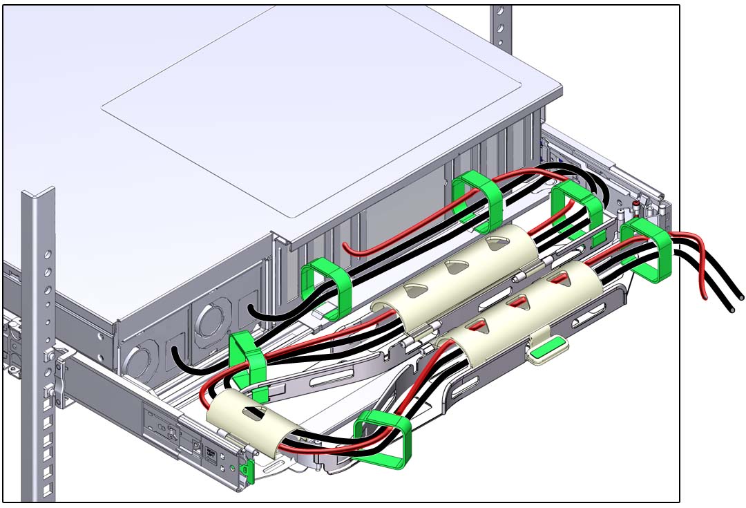
- Ensure that the secured cables do no extend above the top or below the bottom of the storage server to which they are attached; otherwise, the cables might snag on other equipment installed in the rack when the storage server is extended from the rack or returned to the rack.
- If necessary, bundle the cables with additional Velcro straps to ensure that they stay clear of other equipment. If you need to install additional Velcro straps, wrap the straps around the cables only, not around any of the CMA components; otherwise, expansion and contraction of the CMA slide bars might be hindered when the storage server is extended from the rack and returned to the rack.