Remove an Expansion Module

Removal of the Expansion Module is complicated and must be performed by an Oracle Service representative.

Power Down, Lock the Robot, and Remove Magazines

You must park and lock the robot before attempting to remove an Expansion Module.

  1. Power down the library with the option enabled to prepare the robot for removal.
  2. Park and Lock the Robot.
  3. Remove the magazines from the defective module. Remove the magazines from all modules below it, and remove the magazines from the module directly above it.

Remove the Floor, Cables, and Cords

Remove the library floor and any cables or cords connected to the failed module or any module below it.

  1. Grasp the library floor at the thumb-holds within the magazine openings.
  2. Pull the floor out from the front of the bottom module.

    Note:

    If the floor does not move, reach through the magazine opening and push down on the floor behind the touch screen panel to unseat the floor locks. Pull the floor forward with your other hand.

  3. Disconnect the expansion cable plug(s) from the port(s) at each affected Expansion Module controller. Module 6 through Module 10 could have both ports connected.

    Note:

    The original design of the expansion controller had a single port only.

  4. Open the hook and loop strap, extract all cables and cords, then remove the hook and loop strap (open the plunger on the plastic rivet).
  5. Disconnect the power supply cord.
  6. Disconnect the drive interface and Ethernet cables, as applicable.

Remove Operational Expansion Modules Below the Defective Module

To access the defective module, you must remove all modules below it.
  1. Remove tape drives and power supplies to lighten the weight of the Expansion Module.
  2. Remove the Phillips screws securing the Expansion Module to the front of the rack.
  3. Grasp the module, pull it forward until the break in the flange is visible, lower the front of the module, pull it free from the module above it, and away from the rack.
  4. Set the module down and away from the front of the rack.
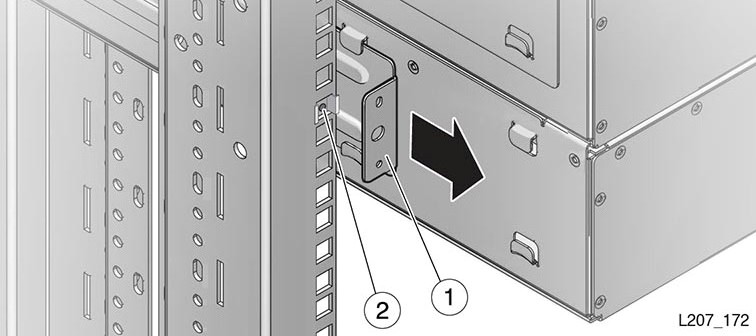
  5. Remove the Phillips screws and rear rails from the module. Leave the clip nut in place.
  6. Repeat until you have removed the all modules below the defective module.

    Figure 10-6 Module Rear Rail Removal

    Module sliding out from rails

    Illustration Legend:

    • 1 - Rear Rail
    • 2 - Clip Nut

Remove Components from the Defective Module

Save functional components to be reused in the replacement module.

  1. Remove the functional components as applicable:
  2. Remove the failed Expansion Module.