| Skip Navigation Links | |
| Exit Print View | |

|
Sun Fire X4170 M2 and X4270 M2 Servers Installation Guide |
1. Preparing to Install the Sun Fire X4170 M2 and X4270 M2 Servers
Server Installation Task Checklist
Sun Fire X4170 M2 Server Supported Components
Sun Fire X4270 M2 Server Supported Components
2. Installing the Server Into a Rack With Slide-Rails
Server Installation Process Overview
Disassemble Bolt-On Slide-Rails
Disassemble Tool-less Slide-Rails
Installing the Mounting Brackets Onto the Server
Attaching the Slide-Rail Assemblies to the Rack
Attach Bolt-On Slide-Rail Assemblies
Attach Tool-less Slide-Rail Assemblies
Installing the Server Into the Slide-Rail Assemblies
Install Server Into the Slide-Rail Assemblies
Installing the Cable Management Arm on the Sun Fire X4270 M2 Server
Verifying Operation of the Slide-Rails and CMA
Verify Operation of Slide-Rails and CMA
3. Attaching Cables and Power Cords
Attaching Cables to the Server
Connecting Power Cords to the Server
4. Connecting to Oracle ILOM and Applying Main Power to the Server
Log In to Oracle ILOM Using a Serial Connection
Log In to Oracle ILOM Using an Ethernet Connection
Test IPv4 or IPv6 Network Configuration
Applying Main Power to the Server
Apply Main Power to the Server
5. Installing or Configuring an Operating System
Installing an Operating System
Configuring a Preinstalled Operating System
6. Configuring the Preinstalled Solaris 10 Operating System
Configuring Server RAID Drives
Configuring the Preinstalled Oracle Solaris 10 Operating System
Configure Oracle Solaris 10 OS
Oracle Solaris 10 Operating System User Information
Oracle Solaris 10 User Documentation
Using the Oracle Solaris Installation Program
Reinstalling the Oracle Solaris Operating System
Download the Solaris Operating System
7. Configuring the Preinstalled Oracle VM Software
Oracle VM Server Configuration
Oracle VM Manager Configuration
Configuring the Preinstalled Oracle VM Software
The cable management arm (CMA) is an optional assembly that you can use to route the server cables in the rack.
Use this procedure to install the optional CMA.
Note - References to “left” or “right” in this procedure assume that you are facing the back of the equipment rack.
The CMA rail extension might be taped to the CMA arm.
Figure 2-8 Inserting the CMA Rail Extension Into the Back of the Left Slide-Rail
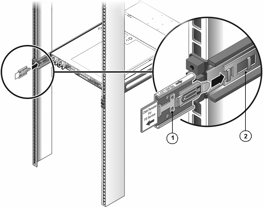
Figure Legend
1 CMA rail extension
2 Left slide-rail
Figure 2-9 Engaging the CMA Rail Extension With the Left Slide-Rail
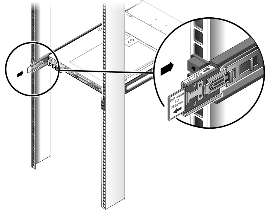
Note - Support the CMA in the remaining installation steps. Do not allow the arm to hang by its own weight until it is secured by all three attachment points.
Figure 2-10 Inserting the CMA Mounting Bracket Into the Back of the Right Slide-Rail
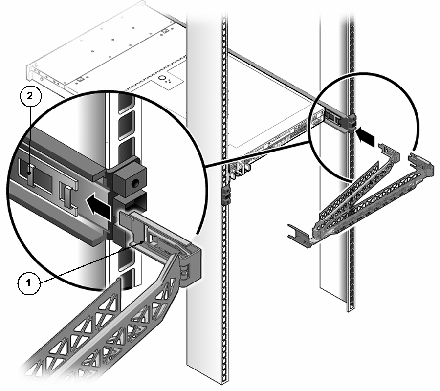
Figure Legend
1 CMA mounting bracket
2 Right slide-rail
Figure 2-11 Inserting CMA Slide-Rail Connector Into the Back of the Right Slide-Rail
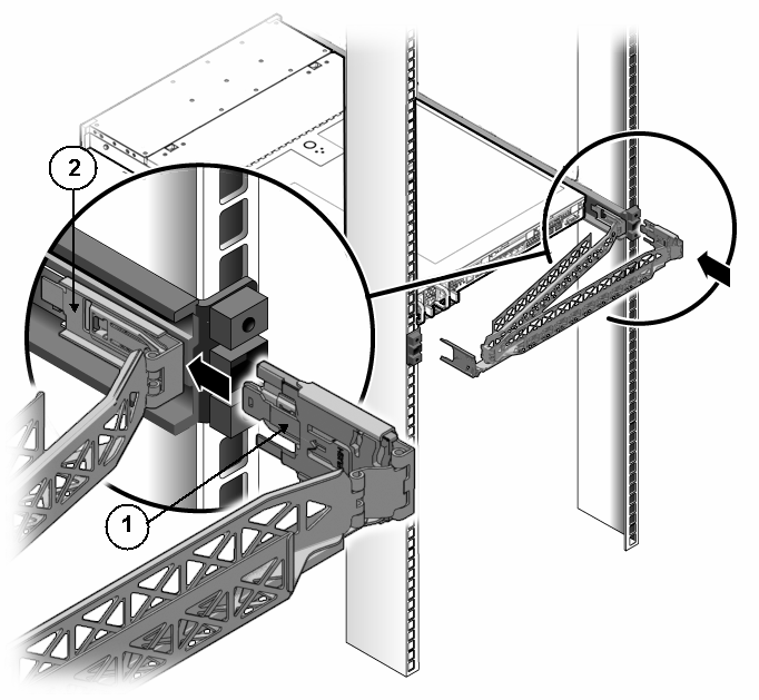
Figure Legend
1 CMA slide-rail connector
2 Right slide-rail
Figure 2-12 Connecting the CMA to the Rail Extension Connector
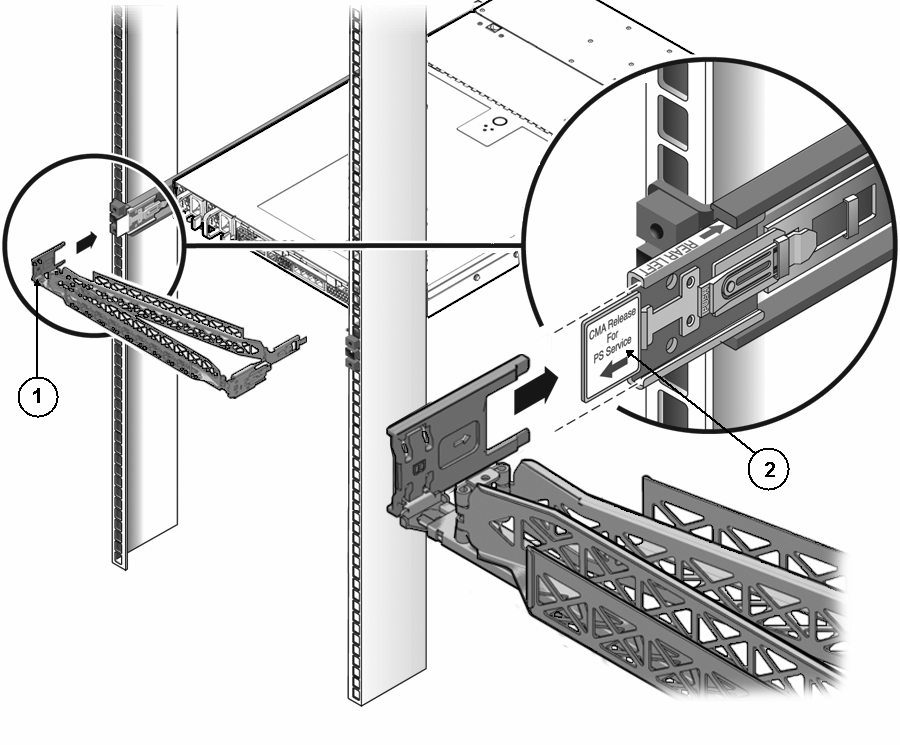
Figure Legend
1 CMA extension arm (on left slide-rail)
2 CMA extension
For best results, place three cable straps, evenly spaced, on the rear-facing side of the CMA and three cable straps on the side of the CMA nearest the server.
Figure 2-13 Installing CMA Cable Straps
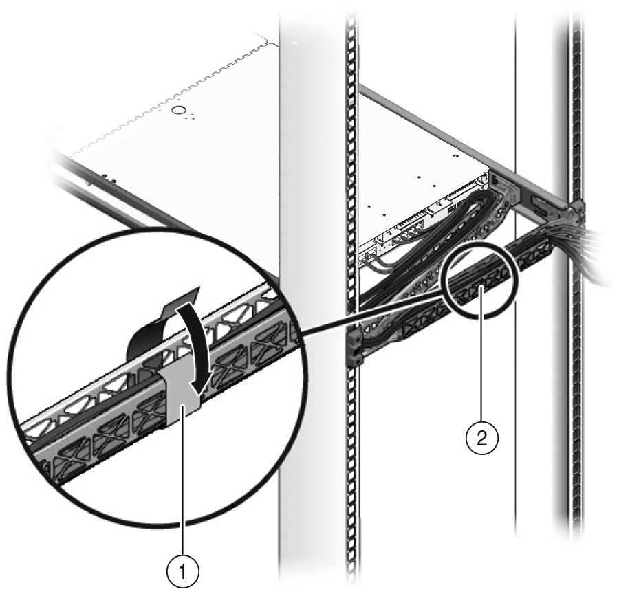
Figure Legend
1 CMA cable strap
2 CMA arm