Skip Headers

Oracle9i Warehouse Builder User's Guide
Release 2 (v9.0.2)

Part Number A95949-01
Go To Documentation Library
Home
Go To Product List
Solution Area
Go To Table Of Contents
Contents
Go To Index
Index

Go to previous page Go to next page

7
Using Mapping Operators and Transformations

This chapter describes how to use Expression Builder to create expressions that operate on the data as it flows from a source to a target. This chapter also describes data flow operators and how to add them to a mapping.

This chapter includes the following topics:

Using Expression Builder

Most of the data flow operators described in this chapter require that you create expressions. An expression is a statement or clause that transforms data. These expressions can be portions of SQL that are used inline as part of a bigger SQL statement. They can also be in other languages such as PL/SQL, SAP, or SQL*Loader. Each expression belongs to a type that is determined by the role of the data flow operator. You can create expressions using Expression Builder, or by typing them into the expression field located in the operator or attribute property inspectors.

You can open Expression Builder from the operator properties inspectors in the following operators:

You can open Expression Builder from the attribute properties inspectors in the following operators:

Figure 7-1 Expression Builder Interface

Text description of expressi.gif follows.

Text description of the illustration expressi.gif

Expression Builder contains the following parts:

To use Expression Builder:

  1. Click the ... button in the expression field located in the operator properties inspector or the attribute properties inspector.

    The Expression Builder displays.

  2. Create an expression.

    You can create an expression by:

    • Typing it into the expression field.

    • Dragging predefined functions available from the navigation tree list and dropping them into the expression field.

    • Clicking operator buttons available below the expression field.

  3. Click Validate.

    This verifies the accuracy of the expression syntax before you save the expression and close the editor.

  4. Click OK.

See "About Mapping Operators" for more information on operators.

Adding Flow Operators to a Mapping

This section describes how to add flow operators to a mapping. Flow operators control the data that moves from sources to targets. They also enable you to change your data as appropriate once it reaches the data target.

To add a flow operator to a mapping:

  1. Drag and drop an icon from the Toolbox onto the Mapping Editor canvas.

  2. Define attributes, procedures, or functions.

  3. Connect the data flow operator to a data source or to a data target.

Before you add data flow operators, you add data source and target operators to your mapping. See "Defining Mappings" for more information.

Adding Mapping Sequences

A Mapping Sequence operator generates sequential numbers that increment for each row. You can connect a Mapping Sequence operator to a target operator input or to the inputs of other types of operators. You can combine the sequence outputs with outputs from other operators.

This operator contains an attribute set named OUTGRP containing two output attributes: CURRVAL and NEXTVAL. NEXTVAL generates a row set of consecutively incremented numbers beginning with the next value and CURRVAL generates from the current value.

You must bind a Mapping Sequence to a repository sequence in one of the modules. You must also reconcile it to that object. The repository sequence must be generated and deployed before the map is deployed to avoid errors in the generated code package for the mapping. See "About Binding Mapping Operators" for more information.

You generate a mapping with a sequence in Row Based mode. Sequences are incremented even if rows are not selected. If you want a sequence to start from the last number, then do not run your SQL package in Set Based or in Set Based With Failover operating modes. See "Setting Runtime Parameters" for more information on configuring mode settings.

The Mapping Sequence operator contains the following property:

To add a mapping sequence operator to a mapping:

  1. Drop the Mapping Sequence operator onto the Mapping Editor canvas.

    The Add Mapping Sequence dialog displays.

  2. Click one of the options.

    • Create a new repository sequence and bind.

    • Import sequence into repository and bind.

    • Select from existing repository sequence and bind.

      This selection contains a search text box and a tree for the sequences stored in the Warehouse Builder repository. Click the appropriate node to locate a sequence. Double-click a sequence to select it.

    For more information on these options, see "Selecting Data Operators".

  3. Connect the sequence to a target attribute.

  4. From the Mapping menu, select Generate and then Mapping.

    The Code Viewer displays generated code for the mapping. The sequence appears in the SELECT list for the insert DML.

Adding Data Generators

Use a Data Generator operator to provide information such as record number, system date, and sequence values. It also provides a place to enter constant information. The Data Generator operator connects the mapping to SQL*Loader to generate the data stored in the database record. The following functions are available:

It is possible for Warehouse Builder to generate data by specifying only sequences, record numbers, system dates, and constants as field specifications. SQL*Loader inserts as many records as are specified by the LOAD keyword.

Setting a Column to the Data File Record Number

Use the RECNUM keyword to set an attribute to the number of the records that the record was loaded from. Records are counted sequentially from the beginning of the first data file, starting with record 1. Because RECNUM is incremented as each logical record is assembled, it increments for records that are discarded, skipped, rejected, or loaded. For example, if you use the option SKIP=10, the first record loaded has a RECNUM of 11.

Setting a Column to the Current Date

A column specified with SYSDATE gets the current system date, as defined by the SQL language SYSDATE function.

The target column must be of type CHAR or DATE. If the column is of type CHAR, then the date is loaded in the format dd-mon-yy. After the load, it can be accessed only in that format. If the system date is loaded into a DATE column, then it can be accessed in a variety of formats that include the time and the date. A new system date/time is used for each array of records inserted in a conventional path load and for each block of records loaded during a direct path load.

Setting a Column to a Unique Sequence Number

The SEQUENCE keyword ensures a unique value for a column. SEQUENCE increments for each record that is loaded or rejected. It does not increment for records that are discarded or skipped.

The combination of column name and the SEQUENCE function is a complete column specification. Table 7-1 lists the options available for sequence values.

Table 7-1 Sequence Value Options 
Value Description

column_name

The name of the column in the database the sequence is assigned to.

SEQUENCE

Specifies the value for a column.

integer

Specifies the beginning sequence number.

COUNT

The sequence starts with the number of records already in the table plus the increment.

MAX

The sequence starts with the current maximum value for the column plus the increment.

incr

The value that the sequence number is to increment after a record is loaded or rejected.

If a record is rejected because of a format error or an Oracle error, the generated sequence numbers are not reshuffled to mask this. For example, if four rows are assigned sequence numbers 10, 12, 14, and 16 in a column, and the row with 12 is rejected, the three rows inserted are numbered 10, 14, and 16, not 10, 12, 14. The sequence of inserts is preserved despite data errors. When you correct the rejected data and reinsert it, you can manually set the columns to match the sequence.

Although the Data Generator operator has only one output group, it has predefined attributes corresponding to Record Number, System Date, and a typical Sequence. Modification of these attributes is not recommended but you can create new attributes. The Data Generator operator is only valid for a SQL*Loader mapping. There can only be one Data Generator operator for a mapping.

The Data Generator contains the following property:

To add a data generator to a mapping:

  1. Drop a Data Generator operator onto the Mapping Editor canvas.

  2. Right-click the RECNUM attribute and select Attribute Properties... from the pop-up menu.

    The RECNUM Attribute Properties inspector displays.
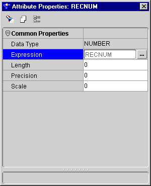
Figure 7-2 RECNUM Attribute Properties Inspector

Text description of recnumpr.gif follows.

Text description of the illustration recnumpr.gif

  1. Enter an expression for RECNUM in the Expression field or click ... to open Expression Builder and define an expression.

  2. Repeat the previous steps for the SYSDATE and SEQUENCE attributes, if necessary.

Adding Constants

The Constant operator enables you to define constants. Constants are initialized at the beginning of the execution of the mapping. Constant values can be used as inputs to a pre-mapping process, a post-mapping process, a mapping output parameter, and other operators in the data flow.

The Constant operator can have only one output attribute group. If the constant defined is of data type VARCHAR or VARCHAR2, the expression must be a valid SQL expression returning a value of data type VARCHAR or VARCHAR2. Constant string literals must be enclosed within single quotes, for example, `my_string'.

The Constant operator contains the following property:

To add a constant operator:

  1. Drop a Constant operator onto the Mapping Editor canvas.

  2. Create an output attribute in the Constant operator output attribute group.

  3. Right-click the attribute and select Attribute Properties from the pop-up menu.

    The Attributes Properties inspector displays.
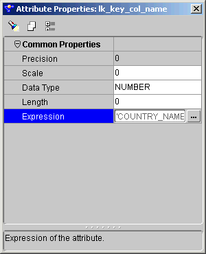
Figure 7-3 Attribute Properties Inspector

Text description of constant.gif follows.

Text description of the illustration constant.gif

  1. Enter an expression into the Expression field or click ... to define an expression using Expression Builder.

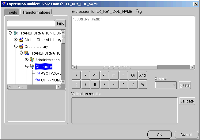
Figure 7-4 Expression Builder Showing A Constant

Text description of constana.gif follows.

Text description of the illustration constana.gif

  1. Close the attribute property editor.

  2. Connect the output attribute to the appropriate target attribute.

  3. From the Mapping menu, select Generate, and then Mapping.

    The Code Viewer displays generated code.

Using Key Lookups

The Key Lookup operator enables you to perform a lookup of data from a lookup object such as a table, view, fact, or dimension. The lookup object is bound to the Key Lookup operator. Use the Key Lookup operator if you have defined surrogate keys on warehouse objects such as dimensions. You can have multiple Key Lookup operators in the same mapping.

The key that you look up can be any unique value. It does not need to be a primary or unique key, as defined in an RDBMS. The Key Lookup operator reads data from a lookup table using the key input you supply and finds the matching row. This operator returns a row for each input key.

The output of the Key Lookup operator corresponds to the columns in the lookup object. If multiple rows in the lookup table match the key inputs, the cardinality of the output differs from the input. This produces results inconsistent with the data flowing into the target operator. To ensure that only a single lookup row is found for each key input row, use keys in your match condition.

You can use Inbound reconciliation on Key Lookup outputs. Outbound reconciliation is disabled. See "Reconciling Mapping Operators with Repository Objects" beginning for more information on reconciliation.

Each output attribute for the key lookup has a property called DEFAULT VALUE. The DEFAULT VALUE property is used instead of NULL in the outgoing row set if no value is found in the lookup table for an input value. The generated code uses the NVL function.

When you validate this operator:

To add a Key Lookup operator:

  1. Drop a Key Lookup operator onto the Mapping Editor canvas.

    The Add Mapping Key Lookup dialog displays.

  2. Click one of the following options:

    • Create a new repository Key Lookup and bind.

    • Select from existing repository Key Lookup and bind.

      This selection contains a search text box and a directory tree for the tables that can be Key Lookup entities. Click the appropriate node to locate a table. Double-click a table to select it.

    A Key Lookup operator displays.


    Note:

    To select multiple items, hold down the Control key as you click each item you want to select. To select a group of items located in a series, click the first object in your selection range, hold down the Shift key, and then click the last object.


  1. Connect the source operator attributes to the input attribute group of the Key Lookup operator.

  2. Right-click the Key Lookup operator header and select Operator Properties from the pop-up menu.

    The Key Lookup Properties inspector displays.
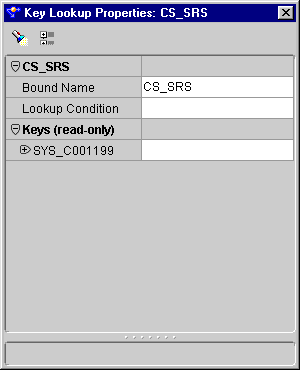
Figure 7-5 Key Lookup Properties Inspector

Text description of mappingk.gif follows.

Text description of the illustration mappingk.gif

  1. Click the field to the right of the Lookup Condition and click the ... button.

    The Lookup Condition dialog displays.
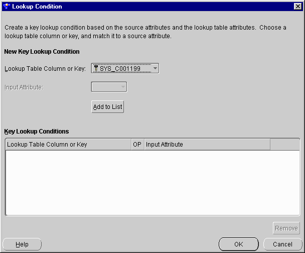
Figure 7-6 Lookup Condition Dialog

Text description of mappinga.gif follows.

Text description of the illustration mappinga.gif

  1. Select the lookup entity attribute from the Lookup Table Column or Key drop-down list.

    Choose attributes to compare to the selected lookup table column.

    For a non-composite key:

    1. Select an Input Attribute from the drop-down list.

    2. Click Add to List.

      The column or input pairs are added to the table at the bottom of the main dialog.

    For a composite key:
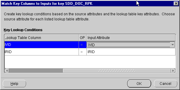
    1. Click Add to List.

      The Match Key Columns to Input for Key dialog displays.

    Figure 7-7 Match Key Columns to Input for Key Dialog

    Text description of mappingm.gif follows.

    Text description of the illustration mappingm.gif

      1. Select the key input attributes from the Input Attribute drop-down list.

      2. Click OK.

    1. Click OK to close the Lookup Condition dialog.

    2. Close the Key Lookup Properties dialog.

    Using Set Operations

    The Set Operation operator enables you to use set operations in a mapping. The operations are:

    • Union (default)

    • Union All

    • Intersect

    • Minus

    The Set Operation operator contains two input groups and one output group. You can add input groups by connecting source operator attributes to the Set Operation operator. Mapping attributes to a Set Operation operator input group creates corresponding attributes with the same name and data type in the Set Operation output group. The number of attributes in the output group matches the number of attributes in the input group containing the most attributes.

    To execute the Set Operation operator:

    • All sets must have the same number of attributes.

    • The data types of corresponding attributes must match.

    Corresponding attributes are determined by the order of the attributes within an input group. For example, attribute 1 in input group 1 corresponds to attribute 1 in input group 2.

    Apply the set operation in top-down order. The order of the input groups determines the execution order of the set operation. This order affects only the minus operation. For example, A minus B is not the same as B minus A. The order of the attributes within an input group determines the structure of a set. For example, {empno, ename} is not the same as {ename, empno}.

    To create sets of data:

    1. Drop a Set Operation operator onto the Mapping Editor canvas.

    2. Connect source operator attributes to the Set Operation operator attribute groups.

    3. Right-click the operator header and select Operator Properties... from the pop-up menu.

      The Set Operation Properties inspector displays.
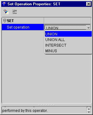
    Figure 7-8 Set Operation Properties Inspector

    Text description of setoppro.gif follows.

    Text description of the illustration setoppro.gif

    1. Click the field to the right of the Set Operation property and select an operation from the drop-down list.

    2. Close the Set Operation Properties inspector.

    3. Connect the Set Operation operator OUTGRP1 attribute group to a target operator input attribute group.

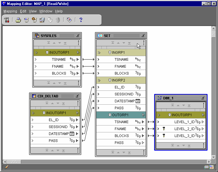
    Figure 7-9 Mapping Showing the Set Operation Operator

    Text description of setopmap.gif follows.

    Text description of the illustration setopmap.gif

    1. From the Mapping menu, select Generate, and then Mapping.

      The Code Viewer displays generated code.

    Joining Data Sources

    You can use the Joiner operator to join multiple row sets from different sources with different cardinalities, and produce a single output row set. The Joiner operator uses a boolean condition expression that relates column values in each source row set to at least one other row set.


    Note:

    Operators placed between data sources and a Joiner can generate complex SQL or PL/SQL. Connect data sources directly to a Joiner.


    If the input row sets are related through foreign keys, that relationship is used to form a default join condition. You can use this default condition or you can modify it. If the sources are not related through foreign keys, then you must define a join condition.

    The following can help you generate queries with optimal performance:

    • Write a join condition statement. You can leave the join condition property for a Joiner operator blank. A blank condition does not generate a validation error in the Expression Builder. By leaving the join condition blank, the Joiner operator brings in all of the source columns despite the number of columns mapped.

    • Define a join condition that relates columns that are not unique or foreign keys in the source table. In this case, create an index on the column in the source row set before attempting to run the generated map.

    • Create a stage table with a column for the transformed column, populate the stage table with another map, and then join the stage table with the other sources. The join condition can contain transformation function calls but this method slows the performance of the generated query.

    • Create a stage table with the transformed data and join the stage table with another source. The join condition can contain arithmetic operators, for example, LINES.PO_OR_ORDER_ID + 10 = ORD.ORDER_ID. All values from the source table must be read and transformed to find the joined rows for a given row.

    The join condition expression cannot contain aggregation functions, such as SUM. Compile errors result when deploying the generated code for the map.

    The Joiner can have an unlimited number of input groups and one output group.

    The Joiner operator contains the following properties:

    • Join Condition (operator level): The text expression template for the Join Condition. For code generation, the input attributes are replaced by the source columns. The expression is a valid SQL expression that can be used in a WHERE clause.

    • Data Type (attributes): The data type of the attribute.

    • Precision (attributes): The precision of the attribute, used for numeric type attributes only.

    • Scale (attributes): The scale of the attribute, used for numeric type attributes only.

    • Length (attributes): The length of the attributes, used for string type attributes only.

    To add a Joiner to a mapping:

    1. Drop the Joiner operator onto the Mapping Editor canvas.

    2. Connect an attribute group from the first source to the INGRP1 group of the Joiner operator.

      The output attributes are created with data types matching the corresponding input data types.
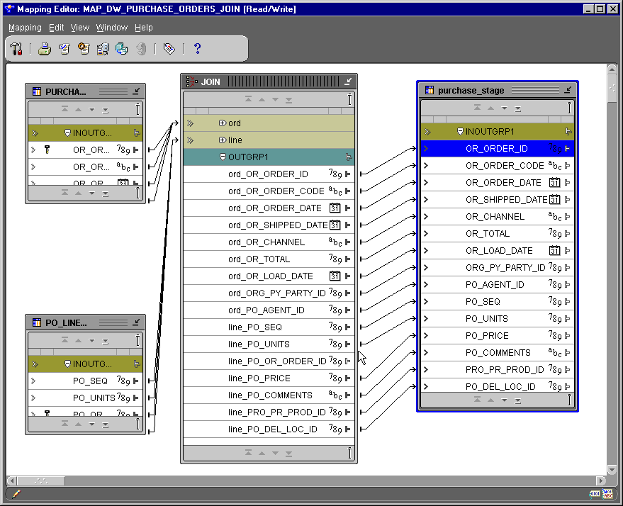

      Tip:

      Rename the input groups on the Joiner operator to reflect their function.


    1. Connect an attribute group from the second source operator to the INGRP2 group of the Joiner operator.

    Figure 7-10 Mapping Editor Showing a Joiner Operator

    Text description of join_ful.gif follows.

    Text description of the illustration join_ful.gif

    1. Right-click the Joiner operator header and select Operator Properties from the pop-up menu.

      The Joiner Properties inspector displays.
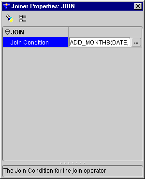
    Figure 7-11 Joiner Properties Inspector

    Text description of join_ope.gif follows.

    Text description of the illustration join_ope.gif

    1. Enter a join condition in the Join Condition field or click ... to define an expression using Expression Builder.

    2. Close the Joiner Properties inspector.

    3. From the Mapping menu, select Generate, and then Mapping.

      The Code Viewer displays generated code. The join condition appears in the WHERE clause of the SELECT query for the insert DML.

    Creating Full Outer Join Conditions

    In an equijoin, key values from the two tables must match. In a full outer join, key values are matched and nulls are created in the resulting table for key values that cannot be matched. A left or a right outer join retains all rows in the specified table.

    In Oracle8i, you create an outer join in SQL using the join condition variable (+):

    SELECT ...
    FROM A, B
    WHERE A.key = B.key (+); 


    This example is a left outer join. Rows from table A are included in the joined result even though no rows from table B match them. To create a full outer join in Oracle8i, you must use multiple SQL statements.

    The Expression Builder allows the following syntax for a full outer join:

    TABLE1.COL1 (+) = TABLE2.COL2 (+) 


    This structure is not supported by Oracle8i. Oracle9i is ANSI SQL 1999 compliant. The ANSI SQL 1999 standard includes a solution syntax for performing full outer joins. The code generator translates the above expression into an ANSI SQL 1999 full outer join statement, similar to:

    SELECT ... 
    FROM table1 FULL OUTER JOIN table2 ON (table1.col1 = table2.col2) 


    Because the full outer join statement complies to ANSI SQL 1999, it is only valid if the generated code is deployed to an Oracle9i database. Specifying a full outer join to an Oracle8i database results in a validation error.

    A full outer join and a partial outer join cannot be used in one SQL statement. If a full outer join and partial outer join are used in the same SQL statement, a validation error occurs.

    To use a full outer join in a mapping:

    1. Follow steps one through four for adding a join operator.

    2. Enter a full outer join statement in the Join Condition field or click ... to define an expression using Expression Builder.

    3. Close the Joiner Operator Property inspector.

    Splitting Data

    You can use the Splitter operator to split a single input row set into several output row sets using a boolean split condition. Each output row set has a cardinality less than or equal to the input cardinality.

    The Splitter operator creates an output group called REMAINING_ROWS containing all input rows not included in any of the other output groups. You can delete this output group, but you cannot edit it.

    The Splitter Operator contains the following properties:

    • Split Condition (output attribute groups): The text expression template for the Split Condition. For code generation, the actual source columns are substituted for the input attribute names in the expression template. Generally, the expression is a valid SQL expression that can be used in a WHERE clause.

    • Data Type (attributes): The data type of the attribute.

    • Precision (attributes): The precision of the attribute, used for numeric type attributes only.

    • Scale (attributes): The scale of the attribute, used for numeric type attributes only.

    • Length (attributes): The length of the attributes, used for string-type attributes only.

    To split data from one source to several targets:

    1. Drop the Splitter operator onto the Mapping Editor canvas.

    2. Connect an attribute group from a source operator to the INGRP1 of the Splitter operator.

      The output attributes are created with data types matching the corresponding input data types.

    3. Right-click the Splitter operator header and select Operator Properties from the pop-up menu.

      The Splitter Properties inspector displays.
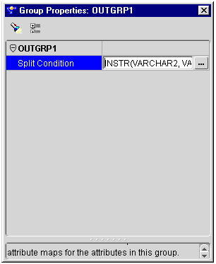
    Figure 7-12 Group Properties Inspector for a Split Condition

    Text description of 07tran19.gif follows

    Text description of the illustration 07tran19.gif

    1. Enter an expression in the Split Condition field or click ... to define an expression using Expression Builder.

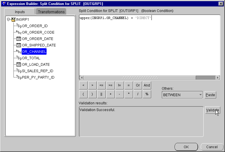
    Figure 7-13 Expression Builder Showing A Split Condition

    Text description of splitter.gif follows.

    Text description of the illustration splitter.gif

    1. Close the Splitter Properties inspector.

    2. Define expressions for each of the output groups.

    3. Connect the output groups to the targets.

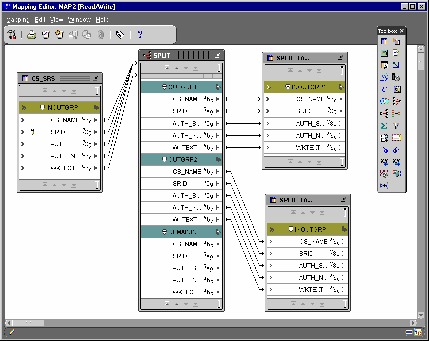
    Figure 7-14 Splitter Operator Mapping

    Text description of splittea.gif follows.

    Text description of the illustration splittea.gif

    1. From the Mapping menu, select Generate, and then Mapping.

      The Code Viewer displays generated code. The generated code displays the split conditions in the WHERE clauses of the SELECT queries for the insert DML. There is a separate select query for each target.

    Removing Redundant Data

    The Deduplicator enables you to remove duplicate data in a source by placing a DISTINCT clause in the select code represented by the mapping.

    To remove redundant data:

    1. Drop the Deduplicator operator onto the Mapping Editor canvas.

    2. Connect the attributes from the source operator to the attribute group INOUTGRP1 of the Deduplicator operator.

    3. Connect the attributes from INOUTGRP1 of the Deduplicator operator to the attributes of the target operator.

    4. From the Mapping menu, select Generate, and then Mapping.

      The Code Viewer displays generated code with a DISTINCT clause in the select statement.

    Aggregating Data

    The Aggregator operator performs data aggregations, such as SUM and AVG, and provides an output row set with aggregated data. Because each Aggregator operator shares a GROUP BY and HAVING clause, each attribute in the output attribute group has the same cardinality. The number of rows in the output row set is less than or equal to the number of input rows.

    The Aggregator operator has one input attribute group and one output attribute group. Connecting the source to the input attribute group produces the corresponding aggregated row set in the output attribute group.

    The Aggregator operator contains the following properties:

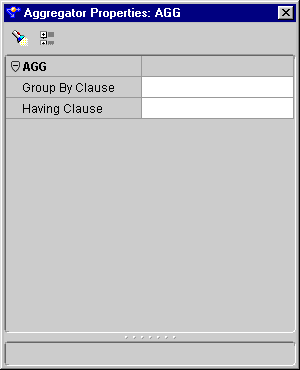
    • Group By Clause (operator level): Defines how the incoming row set is grouped to return a single summary row for each group. An ordered list of attributes in the input attribute group specifies how this grouping is performed.

    • Having Clause (operator level): A boolean condition restricting the groups of rows returned in the output attribute group to those groups for which this condition is true. If this clause is not specified, all summary rows for all groups are returned in the output attribute group. This clause can refer to any attributes or expression of the attributes in the input attribute group.

    • Expression (attribute level): Defines the aggregation functions to be performed on the attribute. If no aggregation function is necessary, specify NONE for the function.

    To add an aggregator to a mapping:

    1. Drop an Aggregator operator onto the Mapping Editor canvas.

    2. Connect source operator attributes to the INGRP1 of the Aggregator operator.

    3. Add the appropriate attributes to the OUTGRP1 attribute group.

      See "Adding or Removing Operator Attribute Groups" for information.

    4. Right-click on an attribute in the Aggregator operator and select Attribute Properties from the pop-up menu.

      The Attribute Properties inspector displays.
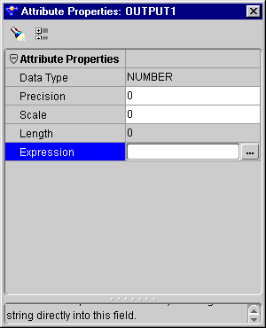
    Figure 7-15 Attribute Properties Inspector

    Text description of aggregat.gif follows.

    Text description of the illustration aggregat.gif

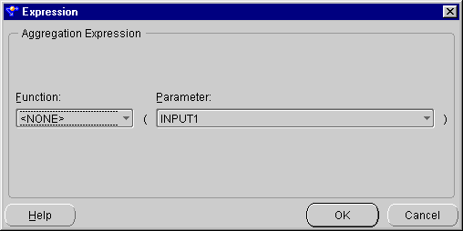
    1. Define expressions for each output attribute.

      1. Click the ... button to the right of the Expression property.

        The Expression dialog displays.

      2. Select a Function and a Parameter from the drop-down lists.

      Figure 7-16 Expression Dialog

      Text description of aggregaa.gif follows.

      Text description of the illustration aggregaa.gif

        1. Click OK.

      1. Click the title bar of the Aggregator operator.

        The Aggregator Properties inspector displays.

      Figure 7-17 Aggregator Properties

      Text description of aggregad.gif follows.

      Text description of the illustration aggregad.gif

      1. Click the ... button to the right of the Group By Clause property.

        The Group By Clause dialog displays.
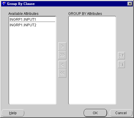
      Figure 7-18 Group By Clause Dialog

      Text description of aggregab.gif follows.

      Text description of the illustration aggregab.gif

      1. Move the attributes to aggregate from the Available Attributes list to the GROUP BY Attributes list.

      2. Click OK.

      3. Click the ... button to define a HAVING clause using Expression Builder.

        Create an expression, for example, sum(INGRP1.OR_TOTAL) > 10000.
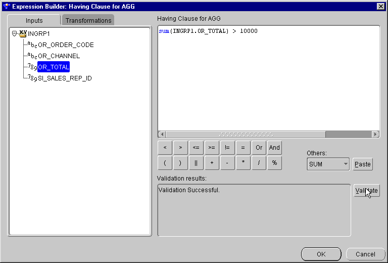
      Figure 7-19 Expression Builder Showing a Sum Statement

      Text description of aggregac.gif follows.

      Text description of the illustration aggregac.gif

      1. Map the attributes you edited from the attribute group OUTGRP1 of the aggregator operator to the attributes in the target.

      2. From the Mapping menu, select Generate, and then Mapping.

        The Code Viewer displays generated code.

      Filtering Data

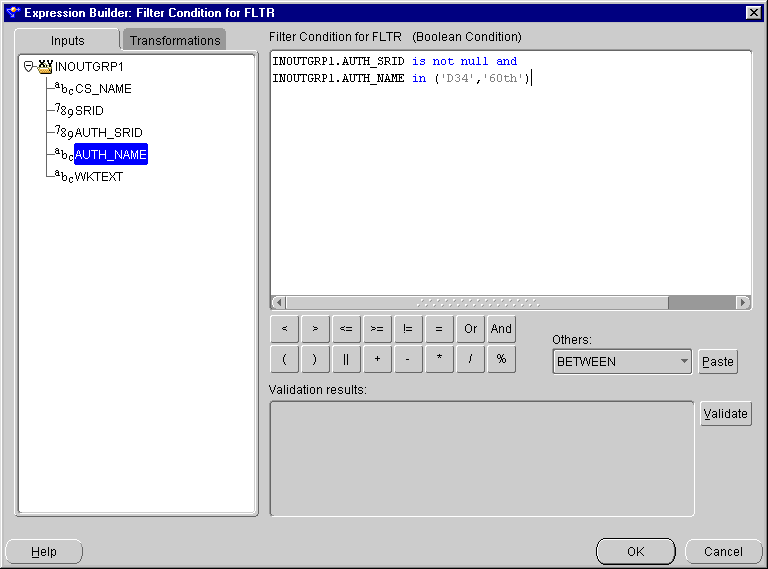
      You can conditionally filter out rows from a row set using the Filter operator. The Filter operator filters data from a source to a target by placing a WHERE clause in the code represented by the mapping. You connect a source operator to the Filter operator, apply a filter condition, and send a subset of rows to the next mapping operator.

      A Filter operator has only one input/output attribute group that can be connected to both a source and target row set. The resulting row set is a filtered subset of the source row set based on a boolean filter condition expression.

      The Filter operator contains the following property:

      • Filter Condition (operator level): The boolean condition that determines which rows are sent to the output row set.

      To filter data:

      1. Drop the Filter operator onto the Mapping Editor canvas.

      2. Connect source operator attributes to the Filter operator INOUTGRP1 attribute group.

      3. Right-click the Filter operator header and select Operator Properties from the pop-up menu.

        The Filter Properties inspector displays.

      Figure 7-20 Filter Properties Inspector

      Text description of filter_o.gif follows.

      Text description of the illustration filter_o.gif

      1. Click the field to the right of the Filter Condition property and enter a filter condition expression or click ... to define a filter condition using Expression Builder.

      Figure 7-21 Expression Builder Showing a Filter Condition

      Text description of filter_e.gif follows.

      Text description of the illustration filter_e.gif

      1. Click OK in Expression Builder and close the Filter Properties inspector.

      2. Connect the Filter operator outputs to the target INOUT attribute group.

      3. Connect source operator attributes to the Filter operator and then to target operator attributes.

      4. From the Mapping menu, select Generate, and then Mapping.

        The Code Viewer displays generated code. The filter condition expressions generated as a WHERE clause for set-based view mode. The filter input names in the original filter condition are replaced by actual column names from the source table, qualified by the source table alias.

      Ordering Data

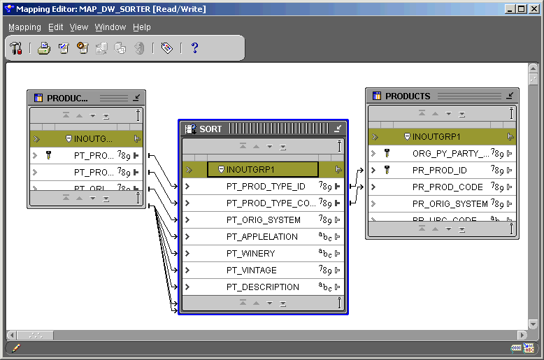
      You can produce a sorted row set using the Sorter operator. The Sorter operator enables you to specify which input attributes are sorted and whether the sorting is performed in ascending or descending order.

      The Sorter operator has one input/output attribute group. This group can be connected from any output or input/output attribute group and to any target input or input/output attribute group. Warehouse Builder sorts data by placing an ORDER BY clause in the code generated by the mapping.

      The Sorter operator contains the following property:

      • Order By Expression (operator level): An ordered list of attributes in the INOUTGRP attribute group specifying that sorting is performed in the same order as the ordered attribute list. You can set ascending or descending sorting for each attribute.

      To order data:

      1. Drop the Sorter operator onto the Mapping Editor canvas.

      2. Connect a source operator attribute group to the Sorter operator INOUTGRP1 attribute group.

      Figure 7-22 Mapping Editor with a Sorter Operator

      Text description of sorter_f.gif follows.

      Text description of the illustration sorter_f.gif

      1. Right-click the Sorter operator header and select Operator Properties from the pop-up menu.

        The Sorter Properties inspector displays.
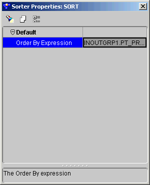
      Figure 7-23 Sorter Properties Inspector

      Text description of sorter_p.gif follows.

      Text description of the illustration sorter_p.gif

      1. Click the ... button in the Order By Expression field.

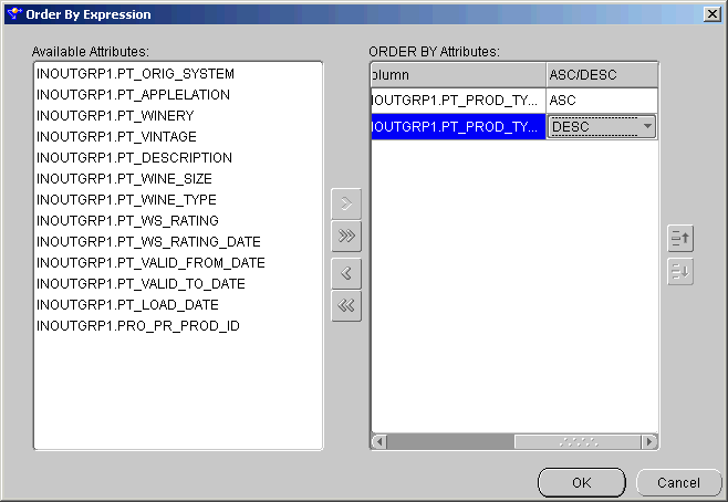
        The Order By Expression dialog displays.

      Figure 7-24 Order By Expression Dialog

      Text description of sorter_e.gif follows.

      Text description of the illustration sorter_e.gif

      1. Select the attributes you want to sort:

        • Select an attribute from the Available Attributes list and click the right arrow button.

        • Click the double right arrow button to select all of the Available Attributes.

      2. Apply an ORDER BY clause to the attribute:

        1. Select the attribute in the ORDER BY Attributes list.

        2. Select ASC (ascending) or DESC (descending) from the drop-down list.

      3. Click OK.

      4. From the Mapping menu, select Generate, and then Mapping.

        The Code Viewer displays generated code.

      Cleansing Name and Address Data

      The Name and Address operator enables you to cleanse data from multiple sources in differing formats. Name cleansing includes both personal name and business name data. You can then map the clean data to a target or to another data flow operator.

      By matching incoming data with data in the Warehouse Builder Name and Address data libraries, the Name and Address operator improves the accuracy and value of your name and address data. This operator enhances the quality of your data by:

      The Name and Address operator parses the data from a source operator into data that can then be reassembled appropriately for your business case. Name and address data is parsed according to these methods:

      • Name Only: Sorts name-related data. Select this when the group contains only name data. A name can include both personal and business names.

      • Address Only: Sorts address-related data. Select this when the group contains only address data and no name data.

      • Name/Address: Sorts both name and address related data (default). Select this when the group contains both name and address data. This option is recommended when you do not know where the name ends and the address begins in your input data.

      After you choose a parsing method, you define Input Roles and Output Components from lists of predefined role types that vary depending on the selected parsing option. Warehouse Builder adjusts the list of available Input Roles and Output Components based on the selected parsing method. Figure 7-25 shows how the Name and Address operator appears on the Mapping Editor canvas.
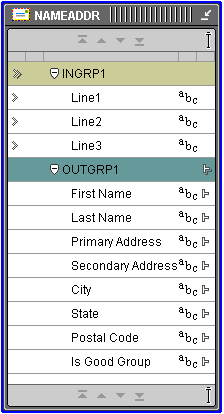
      Figure 7-25 Name And Address Operator

      Text description of nameaddr.gif follows.

      Text description of the illustration nameaddr.gif

      The Name and Address operator contains one input group and one output group, both of which are created automatically when you drop the operator on the mapping editor canvas. You configure the attributes in the input group as Input Roles. An input role represents the input data mapped from a mapping source operator. You configure the attributes in the output group as Output Components.

      Table 7-2 lists the input roles.

      Table 7-2 Input Roles  
      Input Role Description

      None

      This setting causes generation to fail.

      First Name

      First name. This can be a nickname or shortened version of the first name.

      Middle Name

      Middle name or initial.

      Last Name

      Last name (surname).

      First Part Name

      Person, first part, pre-name, first, middle.

      Last Part Name

      Person, last part, last name and title.

      Person

      Full person name, first part and last part.

      Firm Name

      Name of the company or organization, including divisions.

      Address

      Full address line, primary address and secondary address.

      Last Line

      Last address line, city, state, and postal code. Use when city, state or province, and postal code are in one column.

      City

      Name of city.

      State

      Name of state or province.

      Postal Code

      Postal code, such as a ZIP code in the United States or a Postal Code in Canada.

      Country Name

      Full country name.

      Country Code

      The ISO 3166-1993 (E) two-character country code, for example, US for United States or CA for Canada.

      Line1 through Line5

      Intended for use as free-form name, business, personal, and address text. These selections can be used for any type of address system.

      Table 7-3 lists the output components.

      Table 7-3 Output Components  
      Output Component Description

      None

      This setting causes generation to fail.

      Person

      First name, middle name, and last name.

      Pre Name

      Title or salutation appearing before a name.

      First Name

      The first name found in the input name.

      First Name Standardized

      Standard version of first name, for example, Theodore for Ted or James for Jim.

      Middle Name

      Middle name or initial.

      Last Name

      Last name (surname).

      Other Post Name

      Name suffix indicating certification, academic degree, or affiliation (Ph.D, M.D., R.N.).

      Firm Name

      Name of the company or organization, including divisions.

      Gender

      Probable gender (M=Male, F=Female, N=Neutral-gender is not defined).

      Person Count

      Number of personal names found in the Name Only or Name and Address groups.

      Address

      full address line, both primary and secondary.

      Primary Address

      Street name, house number, city map grid direction (SW, N), street type (avenue, street, road, etc.); does not include apartment or unit information.

      Secondary Address

      Unit designator and number, for example, Apt 3G.

      Street Name

      Name of street.

      City

      Name of city; US city names may be converted to United States Postal Service preferred names.

      State

      Name of state or province; this may be a county name for countries such as the United Kingdom.

      Postal Code

      Full postal code with spaces and other non-alphanumeric characters removed.

      Postal Code Formatted

      Formatted version of postal code that includes spaces and other non-alphanumeric characters, such as dashes.

      Last Line

      Neighborhood, city, state (or province), formatted postal code if address was fully assigned. If state contains a county instead of a state or province, it is not included.

      Country Name

      The full country name.

      Latitude

      Latitude in degrees north of the equator; positive for north of the equator, negative for south (always positive for North America).

      Longitude

      Longitude in degrees east of the Greenwich Meridian; positive for east of GM, negative for west (always negative for North America).

      Address Type

      Type of Address. T=Firm, G=General Delivery, H=High-rise apartment or office building, HD= High-rise default (the Name and Address operator can detect a finer level of postal code assignment if further input information were available), B=Box; R=Rural Code; S=Street.

      Is Found

      Indicates whether the address is listed in the postal matching database for the country indicated by the address. T=The address was found in a postal matching database. F=The address was not found in a postal matching database. This may mean that the address is not a legal address, but may also indicate that postal matching is not available for the country.

      Is Parsed

      T=The name or address was parsed successfully. A name or address is considered to be successfully parsed even if some parsing errors exist. F=The name or address may not be parsed.

      Is Good Group

      Indicates whether the name group, address group, or name and address group was processed successfully. For name groups, this means the name has been successfully parsed; for address groups, the address has been found in a postal matching database if one is available, or has been successfully parsed if no postal database is installed. For name and address groups, both the name and the address have been successfully processed.

      Is Good Address

      Indicates whether the address was processed successfully. T=successfully processed: either the address was found in the postal matching database or if no postal matching database is installed for the country indicated by the address, the address was successfully parsed. F=not successfully processed: if a postal matching database is installed for the country indicated by the address, this indicates that address was not found in the database. If no postal matching database is available for the country, this indicates that the address may not be parsed.

      Is Good Name

      Indicates whether the name was parsed successfully. T=The name was parsed successfully. Note that a name is considered to be successfully parsed even if some parsing errors exist. F=The name may not be parsed.

      Is Address Verifiable

      Indicates whether postal matching is available for the address. T= Postal matching is available for the address. This indicates that a postal matching database is installed for the country indicated by the address; matching is not available for the address. No postal matching database is installed for the country indicated by the address.

      After parsing and matching the data, you are ready to map from the output parameter group to a target operator.

      To cleanse name and address data:

      1. Drop the Name and Address operator onto the Mapping Editor canvas.

      2. Connect the source operator attributes to the Name and Address operator attribute group labeled INGRP1.

      3. Right-click the Name and Address operator header and select Operator Properties from the pop-up menu.

        The Name and Address Properties inspector displays.
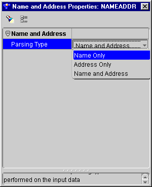
      Figure 7-26 Name and Address Operator Property Inspector

      Text description of nameadda.gif follows.

      Text description of the illustration nameadda.gif

      1. Click the field to the right of the Parsing Type property and select a parsing type from the drop-down list.

      2. Close the Name and Address Properties inspector.

      3. Connect the source operator attributes to the Name and Address attributes.

      4. Define the Input Role for each input attribute.

        1. Right-click an input attribute and select Attribute Properties from the pop-up menu.

          The Attribute Properties inspector displays.
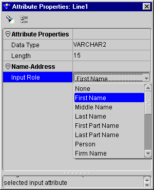
        2. Select an item from the drop-down list to the right of the Input Role field.

        Figure 7-27 Attribute Properties Inspector Showing the Input Role

        Text description of nameaddc.gif follows.

        Text description of the illustration nameaddc.gif

        1. Define the Output Component for each output attribute.

          1. Right-click an output attribute and select Attribute Properties from the pop-up menu.

            The Attribute Properties inspector displays.
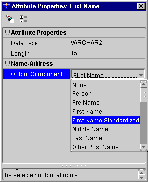
          2. Select an item from the drop-down list located to the right of the Output Component field.

        Figure 7-28 Attribute Properties Inspector Showing the Output Component

        Text description of nameaddb.gif follows.

        Text description of the illustration nameaddb.gif

        1. Connect the Name and Address operator outputs to a target attribute group.

        2. From the Mapping menu, select Generate, and then Mapping.

          The Code Viewer displays generated code.

        Adding a Pre-Mapping Process

        The Pre-Mapping Process operator calls a function or procedure whose metadata is defined in Warehouse Builder prior to executing a mapping. The output parameter group provides the connection point for the returned value (if implemented with a function) and the output parameters of the function or procedure. There are no restrictions on the connections of these output attributes

        When you drop a Pre-Mapping Process operator onto the Mapping Editor canvas, a dialog opens displaying the available libraries, categories, functions, and procedures. You select a function or procedure from the tree, and the operator displays with predefined input and output parameters.

        The Pre-Mapping Process operator has attribute groups corresponding to the number and direction of the parameters associated with the selected PL/SQL procedure or function. You can modify this list by using reconciliation.

        There can be only one Pre-Mapping Process operator for a mapping. Only constants, mapping input parameters, and output from a Pre-Mapping Process can be mapped into a Post-Mapping Process operator.


        Note:

        Constants, Sequences, Data Generators, and Mapping Input Parameters can precede Pre-Mapping Processes.


        To add a pre-mapping process operator to a mapping:

        1. Drop a Pre-Mapping Process operator onto the Mapping Editor canvas.

          The Add Mapping Transformation dialog displays.
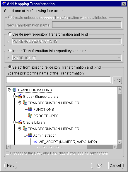
        Figure 7-29 Add Mapping Transformation Dialog

        Text description of preproce.gif follows.

        Text description of the illustration preproce.gif

        1. Select a procedure from the selection list.

        2. Connect the output attribute of the Pre-Mapping Process operator to the input attribute group of a target operator.

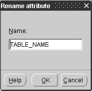
        3. Rename the operator:

          1. Right-click the operator header.

          2. Select Rename from the pop-up menu.

          3. Enter a new name.

          4. Click OK.

        Figure 7-30 Rename Attribute Dialog

        Text description of preproca.gif follows.

        Text description of the illustration preproca.gif

        1. From the Mapping menu, select Generate, and then Mapping.

          The Code Viewer displays generated code.

        Adding a Post-Mapping Process

        The Post-Mapping Process operator calls a function or procedure whose metadata is defined in Warehouse Builder after the map is executed. The output parameter group provides the connection point for the returned value (if implemented via a function) and the output parameters of the function or procedure. There are no restrictions on the connections of these output attributes

        The Post-Mapping Process operator has attribute groups corresponding to the number and direction of the parameters associated with the selected PL/SQL procedure or function. This list of groups and attributes can only be modified through reconciliation.

        There can be only one Post-Mapping Process operator for a mapping. Only constants, mapping input parameters, and output from a Pre-Mapping Process can be mapped into a Post-Mapping Process operator. The Post-Mapping Process operator is not valid for an SQL*Loader mapping.


        Note:

        Constants, Sequences, Data Generators, and Mapping Input Parameters can precede Post-Mapping Processes.


        To add a post-mapping process operator to a mapping:

        1. Drop a Post-Mapping Process operator onto the Mapping Editor canvas.

          The Add Mapping Transformation dialog displays.
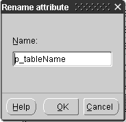
        Figure 7-31 Add Mapping Transformation Dialog

        Text description of postproc.gif follows.

        Text description of the illustration postproc.gif

        1. Select the appropriate procedure from the selection list.

        2. Connect the output attribute of a source operator to the INOUTGRP1 of the Post-Mapping Process operator.

        3. Rename the operator:

          1. Right-click the operator header.

          2. Select Rename from the pop-up menu.

          3. Enter a new name.

          4. Click OK.

        Figure 7-32 Rename Attribute Dialog

        Text description of postproa.gif follows.

        Text description of the illustration postproa.gif

        1. From the Mapping menu, select Generate, and then Mapping.

          The Code Viewer displays generated code.

        Adding Mapping Input Parameters

        A Mapping Input Parameter operator enables you to pass parameter values into a mapping. The Mapping Input Parameter operator has a cardinality of one and it creates a single row set that can be combined with another row set as input to the next operator.

        The names of the input attributes become the names of the mapping output parameters. The parameters can be used by connecting the attributes of the Mapping Input Parameters operator within the mapping editor. You can have only one Mapping Input Parameter operator in a mapping.

        The default value for the mapping input parameter appears in the DEFAULT clause following the function parameter declarations in the generated PL/SQL package. For example, if a mapping parameter named param1 with data type VARCHAR2 is defined with a default value of 'HELLO', the generated main function in the PL/SQL package appears as:

              ... param1 IN VARCHAR2 DEFAULT 'HELLO'...

        If a mapping parameter output named param1 has the data type VARCHAR2, the generated main function in the PL/SQL package appears as:

              ... param1 IN VARCHAR2 ...

        The Mapping Input Parameter operator contains the following properties:

        To add a Mapping Input Parameter operator to a mapping:

        1. Drop a Mapping Input operator onto the Mapping Editor canvas.

        2. Add an attribute to the Mapping Input operator:

          1. Right-click the MAP_INPUT attribute group.

          2. Select Add/Remove Attributes from the pop-up menu.

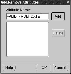
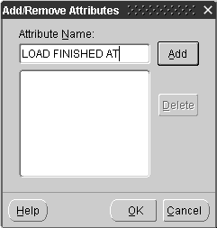
          3. Add a name for the attribute in the Add/Remove Attributes dialog.

          4. Click OK.

        Figure 7-33 Add/Remove Attributes Dialog

        Text description of inputpar.gif follows.

        Text description of the illustration inputpar.gif

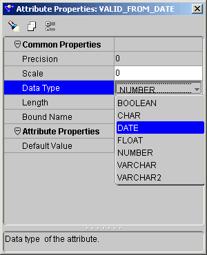
        1. Change the Data Type for the new attribute:

          1. Right-click the new property.

          2. Select Attribute Properties from the pop-up menu.

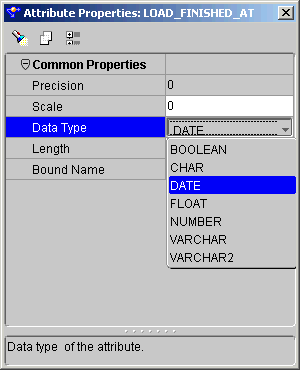
          3. Select a new data type from the drop-down list.

          Figure 7-34 Attribute Properties Inspector

          Text description of inputpaa.gif follows.

          Text description of the illustration inputpaa.gif

          1. Connect the Input Parameter operator MAP_INPUT attribute to an attribute group of the target operator.

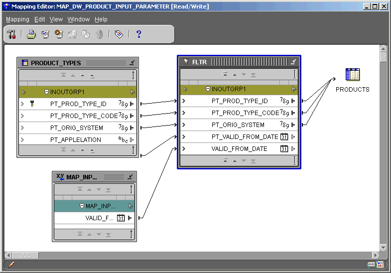
          Figure 7-35 Mapping Editor Showing A Mapping Input Parameter Operator

          Text description of inputpab.gif follows.

          Text description of the illustration inputpab.gif

          1. From the Mapping menu, select Generate, and then Mapping.

            The Code Viewer displays generated code.

          Adding Mapping Output Parameters

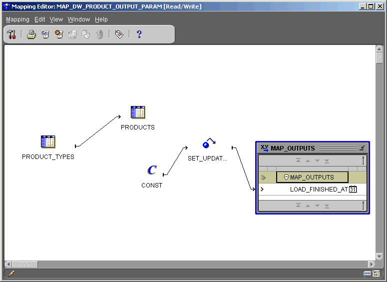
          The Mapping Output Parameter operator enables you to send values out of a mapping. The Mapping Output Parameter operator must have only one input attribute group. You can have only one Mapping Output Parameter operator in a map. Attributes not associated with a row set can be mapped into a Mapping Output Parameter operator. For example, constant, input parameter, output from a pre-mapping process, or output from a post process can all contain attributes not associated with a row set. A Mapping Output Parameter operator is not valid for a SQL*Loader mapping.

          The default value for the mapping output parameter appears in the DEFAULT clause following the function parameter declarations in the generated PL/SQL package. For example, if a mapping parameter named param1 with data type VARCHAR2 is defined with a default value of 'HELLO', the generated main function in the PL/SQL package appears as:

              ... param1 OUT VARCHAR2 DEFAULT 'HELLO' ...

          If a mapping parameter output named param1 has data type VARCHAR2, the generated main function in the PL/SQL package appears as:

              ... param1 OUT VARCHAR2 ...

          The Mapping Output Parameter operator contains the following properties:

          To add a mapping output parameter to a mapping:

          1. Drop a Mapping Output Parameter operator onto the Mapping Editor canvas.

          2. Add an output attribute to the Mapping Output Parameter operator.

            1. Right-click the MAP_OUTPUT attribute group.

            2. Select Add/Remove Attributes from the pop-up menu.

            3. Add a name for the attribute in the Add/Remove Attributes dialog.

            4. Click OK.

          Figure 7-36 Add/Remove Attributes Dialog

          Text description of outputpb.gif follows.

          Text description of the illustration outputpb.gif

          1. Change the data type of the new attribute:

            1. Right-click the new property.

            2. Select Attribute Properties from the pop-up menu.

            3. Select a new data type from the drop-down list.

            4. Close the Attribute Properties inspector.

            Figure 7-37 Attribute Properties Inspector

            Text description of outputpc.gif follows.

            Text description of the illustration outputpc.gif

            Figure 7-38 Mapping Editor Showing An Output Parameter Operator

            Text description of outputpa.gif follows.

            Text description of the illustration outputpa.gif

            1. From the Mapping menu, select Generate, and then Mapping.

              The Code Viewer displays generated code.

            Adding External Processes

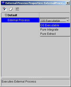
            The External Process operator enables you to represent a process not defined by Warehouse Builder to incorporate it into a mapping. The External Process operator is a self-contained operation and requires no inputs or outputs. During code generation, Warehouse Builder generates a job control code (TCL script) for external process operators that can be deployed as part of the Warehouse Builder workflow.

            The following types of processes are available in Warehouse Builder:

            • OS Executable

            • Pure Integrate

            • Pure Extract

            To add an External Process operator to a mapping:

            1. Drop an External Process operator onto the Mapping Editor canvas.

            2. Right-click the External Process operator header and select Operator Properties from the pop-up menu.

              The External Process Properties inspector displays.

            Figure 7-39 External Process Properties Inspector

            Text description of external.gif follows.

            Text description of the illustration external.gif

            1. Click the External Process field and select one from the drop-down list.

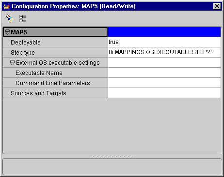
            2. From the Warehouse Module Editor, right-click the map containing the External Process operator and select Configure from the pop-up menu.

              The Configuration Properties inspector displays.

            Figure 7-40 External Process Configuration Properties Inspector

            Text description of externaa.gif follows.

            Text description of the illustration externaa.gif

            1. For OS Executable and Pure Integrate processes, enter:

              • Executable Name: The directory path and name of the executable.

              • Command Line Parameters: The string of parameters to be passed to the executable.

            2. For Pure Extract processes, enter:

              • FTP Directory: Directory for performing FTP.

              • Status File name: The file containing the execution status of the Pure Extract process.

            3. Close the Configuration Properties inspector.

            4. From the Mapping menu, select Generate, and then Mapping.

              The Code Viewer displays generated code.

            Adding Transformations

            You use the Mapping Transformation operator to transform the column value data of rows within a row set using a PL/SQL function, while preserving the cardinality of the input row set.

            The Mapping Transformation operator must be bound to a function or procedure contained by one of the modules in the repository. The inputs and outputs of the Mapping Transformation operator correspond to the input and output parameters of the bound repository function or procedure. Also, if the Mapping Transformation operator is bound to a function, a result output is added to the operator that corresponds to the result of the function. The bound function or procedure must be generated and deployed before the mapping can be deployed, unless the function or procedure already exists in the repository.

            Warehouse Builder provides pre-defined PL/SQL library functions in the runtime schema that can be selected as a bound function when dropping a Mapping Transformation operator onto a mapping. In addition, you can choose a function or procedure from the Global Shared Library.

            The Mapping Transformation operator contains the following properties:

            • Function Call (operator level, read-only): The text template for the function call that is generated by the code generator for the, with the operator attribute names listed as the calling parameters. For the actual call, the operator attribute names are replaced with the actual source or target columns that are connected to the attributes.

            • Function Name (operator level, read-only): The name of the function or procedure, to which this operator is bound.

            • Procedure (operator level, read-only): A boolean value indicating, if true, that the bound transformation is a procedure rather than a function with no returned value.

            • Data Type (attributes, read-only): Indicates the data type of the input, output, or result parameter of the bound function that corresponds to the given attribute.

            • Default Value (input attributes, read-only): The default value (blank if none) for the given attribute.

            • Optional Input (input attributes, read-only): A boolean value indicating, if true, that the given attribute is optional. If the attribute is optional, it need not be connected in the mapping.

            • Function Return (output attributes, read-only): A boolean value indicating, if true, that the given output attribute is the result attribute for the function. The result attribute is a named result. Use this property if another output is a named result, or if you change the name of the result output.

            To add a mapping transformation operator:

            1. Drop a Mapping Transformation operator onto the Mapping Editor canvas.

              The Add Mapping Transformation dialog displays.
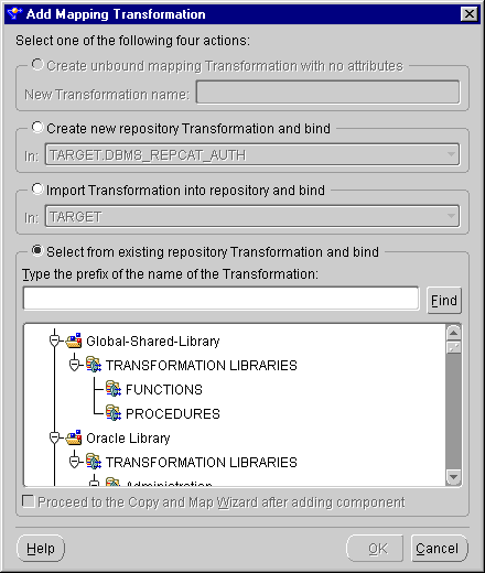
            2. Select one of the following options:

              • Create a new transformation repository and bind.

              • Import existing transformation into repository and bind.

              • Select from existing repository transformation and bind.

                This selection contains a search text box and a directory tree for all the transformations stored in the Warehouse Builder repository. Click the appropriate node to locate a transformation. Double-click a transformation to select it.

              For more information on these options, see "Selecting Data Operators" beginning.


              Note:

              To select multiple items, hold down the Control key as you click each item you want to select. To select a group of items located in a series, click the first object in your selection range, hold down the Shift key, and then click the last object.


            1. Connect the source attributes to the inputs of the Mapping Transformation operator.

            2. (Optional step) Right-click one of the inputs and select Attribute Properties from the pop-up menu.

              The Mapping Transformation Properties inspector displays.
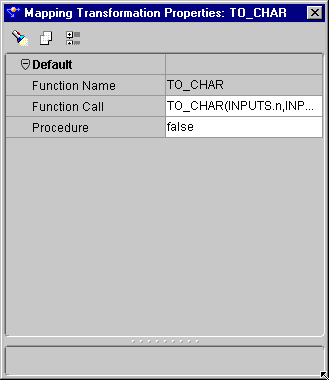
            Figure 7-41 Mapping Transformation Properties Inspector

            Text description of trfm_ope.gif follows.

            Text description of the illustration trfm_ope.gif

              1. Select an input attribute.

              2. If the Procedure property is set to True, then do not connect the input parameter.

              3. Close the attribute property inspector.

            1. Connect the Transformation operator output attributes to the target attributes.

            2. From the Mapping menu, select Generate, and then Mapping.

              The Code Viewer displays generated code.

            Adding Expressions

            The Expression operator enables you to write SQL expressions that define non-procedural algorithms for one output parameter of the operator. The expression text can contain combinations of input parameter names, variable names, and library functions. Use the Expression operator to transform the column value data of rows within a row set using SQL-type expressions, while preserving the cardinality of the input row set. To create these expressions, open the Attribute Property inspector for the output attribute and open Expression Builder.

            You can have only one input attribute group and one output attribute group in the Expression operator, both of which are created automatically when you drop the operator onto the Mapping Editor canvas.

            The output expressions for this operator cannot contain any aggregation functions. To use aggregation functions, use the Aggregator operator.

            The Expression operator contains the following properties:

            • Data Type (attributes): The data type of the attribute.

            • Precision (attributes): The precision of the attribute, used for numeric type attributes only.

            • Scale (attributes): The scale of the attribute, used for numeric type attributes only.

            • Length (attributes): The length of the attributes, used for string type attributes only.

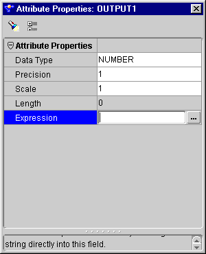
            • Expression (output attributes): The text expression template for the output attribute. For code generation, the input attributes are replaced by the input attribute names in the expression template.

            To add an expression operator:

            1. Drop an Expression operator onto the Mapping Editor canvas.

            2. Connect the appropriate source attributes to the INGRP of the Expression operator.

              This automatically creates the input attributes.
            3. Create an output attribute in the Expression operator output attribute group:

              1. Right-click OUTGRP.

              2. Select Add/Remove Attributes from the pop-up menu.

              3. Add an attribute.

              4. Click OK.

            4. Right-click the output attribute and select the Attribute Properties from the pop-up menu.

            Figure 7-42 Attribute Properties Inspector

            Text description of expressb.gif follows.

            Text description of the illustration expressb.gif

            1. Click the field to the right of the Expression property and enter a filter condition expression or click ... to open Expression Builder and define an expression.

            2. Close the attribute properties inspector.

            3. Connect the Expression output attribute to the appropriate target attribute.

            4. From the Mapping menu, select Generate, and then Mapping.

              The Code Viewer displays generated code.

            The next chapter, Chapter 8, "Configuring and Generating Mappings" shows you how to configure your mapping for generating deployment code.


Go to previous page Go to next page
Oracle
Copyright © 1996, 2002 Oracle Corporation.

All Rights Reserved.
Go To Documentation Library
Home
Go To Product List
Solution Area
Go To Table Of Contents
Contents
Go To Index
Index