10g (9.0.4)
Part Number B10188-01
Home |
Solution Area |
Contents |
Index |
| Oracle Application Server Wireless Administrator's Guide 10g (9.0.4) Part Number B10188-01 |
|
This chapter includes the following sections:
System Administrators use the System Manager to manage the Wireless site and server as well as to manage and configure processes and monitor system performance data to assess system health, and centrally manage and configure Wireless. All configuration data is stored in the database. In addition, the System Manager enables users to upload and download repository objects.
The System Manager, which is part of Oracle Enterprise Manager in integrated mode, provides you with two views to manage the Wireless system: the Wireless Server view and the Site view. The Wireless Server view enables you to monitor and manage system performance for each server and to start and stop the server processes. From the Site view, you create a common configuration for the Wireless servers, and monitor the performance data for the entire site.
You access these views (and the functions they provide) through the three subtabs of the System Manager: Home, Site Performance and Site Administration. Table 3-1 describes these tab and their functions. Figure 3-1 depicts a partial view of the System Manager's Home page, which appears by default when you access the tool.
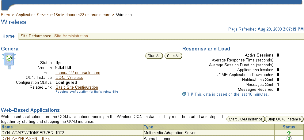
The Home, Site Performance and Administration pages each have a timestamp that indicates the status of the data displayed on the page. To update this data, click the the Refresh icon. Refreshing the Home and Site Performance pages reloads the performance or status information, not the configuration data. To refresh the configuration data (that is, to force the configuration data to be reloaded from the database), click the refresh icon on the Site Administration page. The timestamp on the Home and Site Performance pages displays the current time, because the data is retrieved in real-time; the timestamp on the Site Administration page, however, displays the last time that the configuration data was loaded from the database. To refresh the page, you must either click the Refresh icon or update some configuration data.

You can log into the System Manager through the standalone mode or through the Oracle Enterprise Manager Application Server Control.
To access the login page for the System Manager in standalone mode, enter the following URL into a browser:
http://9iASWEServer.domain:port/webtool/login.uix
For example, enter:
http://9iASWEServer.domain:7777/webtool/login.uix
After you enter your user name and password, the System Manager appears, defaulting to the Home subtab.
To access the System Manager from the standalone version of the Oracle Enterprise Manager Application Server Control, you must first enter the following URL into a browser:
http://Server:1810/emd/console
After you log into the OEM, select the Wireless component from the System Components table. The System Manager appears and defaults to the Home page (Figure 3-3).
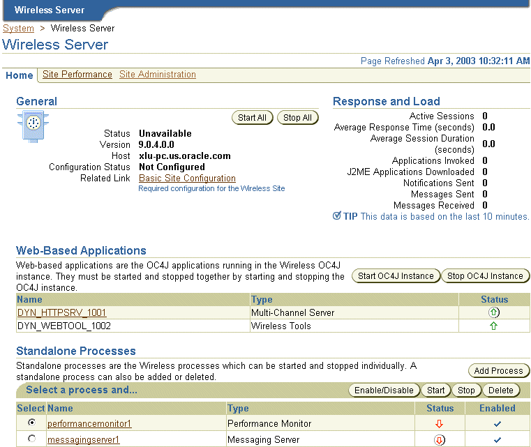
After you access the System Manager, the tool defaults to the Home page. The page's General section displays current status of the Wireless server (Up, Down, or Unavailable), the name of the current host, the version number of Oracle Application Server Wireless and the configuration status of the site. The timestamp on the Home page reflects the current status of the data displayed on the page. You can refresh (reload) the Home page by clicking the Refresh icon.
The Home page is divided into the following sections:
The General section lists the current status of the Wireless server, the name of the current host, and if the server has been configured.
The Response and Load section displays the following Wireless runtime instance statistics for the last ten minutes.
This section lists the OC4J (Oracle Containers for Java) applications in the Wireless OC4J instance. These application types vary according to the installation. The System Manager displays each of the applications as a hyperlink; by clicking one, you access pages for viewing performance statistics. You can refresh the performance data displayed on these paged by clicking the Refresh icon. These applications, which are started or stopped using the Start OC4J Instance and Stop OC4J Instance buttons, are started as stopped as a group; these applications cannot be started or stopped individually.
This section lists the Wireless process types, which vary according to the installation. The System Manager displays each of the processes as a hyperlink; by clicking one, you access detail pages that enable you to start and stop the process, view its performance statistics, and configure it. You can refresh data on the detail pages by clicking the Refresh icon.
From this section (pictured in Figure 3-4), you can configure the logging directory, view the log file, and configure the URLs for the current Wireless instance or middle tier.

The General section includes a link called Basic Site Configuration, which enables you to quickly configure the entire Oracle Application Server Wireless site by providing a minimum of information.
|
Note: The site needs only to be configured once after the installation of the first Wireless middle tier. |
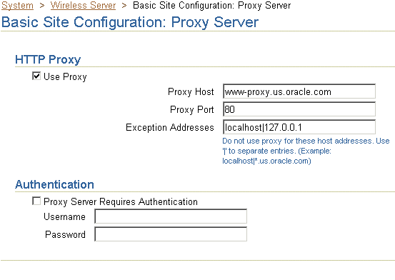
Clicking the link invokes a two-page wizard that guides you through the configuration of the Wireless site. The pages are as follows:
You configure the site's locale and time zone using the drop-down lists in the Site Locale section.
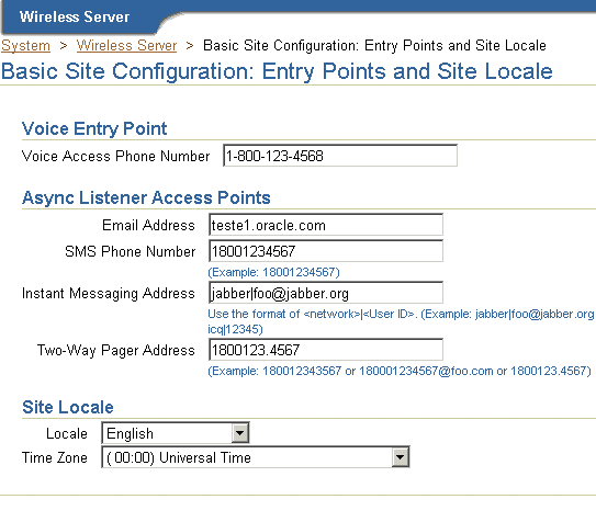
After you complete this wizard, the configuration status in General section displays as Configured.
From the System Logging section on Home page (pictured in Figure 3-7), you can designate the location for the system logging and view the system log file.

To configure the logging directory:
|
Note: For the log directory change to take effect, you must restart all of the Wireless processes, including Wireless OC4J Instance and all the standalone processes. |
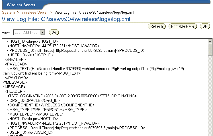
You can view a log file by clicking the View Log File link. Depending on the log level specified at Site level, you can view error messages, warning messages and notify messages. Wireless provides extensive runtime exception logging. When fatal exceptions occur, Wireless logs the exceptions and stack traces in the system log file.
Using the View Log File page (Figure 3-8), you specify the number of lines from the end of the log file that the System Manager displays. You can also print a selected segment of the file as a text file by clicking Printable Page. The page displays the segment of the log file to be printed. Use the browser's back button to navigate from this page.
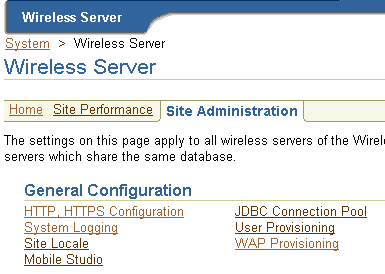
From the General Configuration section (Figure 3-9) on the Site Administration page, you can change the log level for the whole using the configuration page accessed by clicking System Logging.
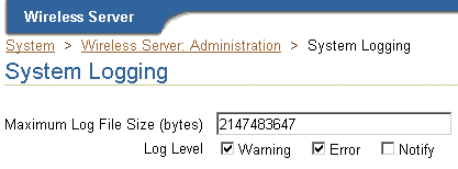
From the System Logging page (Figure 3-10), you specify the log file size in bytes, and the log levels: Error, Warning, and Notify. By default, error and warning messages will be logged in the system log file.
From the Instance URLs page (depicted in Figure 3-11), you to specify the URLs used by a Wireless middle-tier server as entry points to the Wireless services. This page enables you to define the instance URLs (that is, the local URLs) for a middle-tier server, or direct a middle-tier server to use the URLs defined for the entire Wireless site.
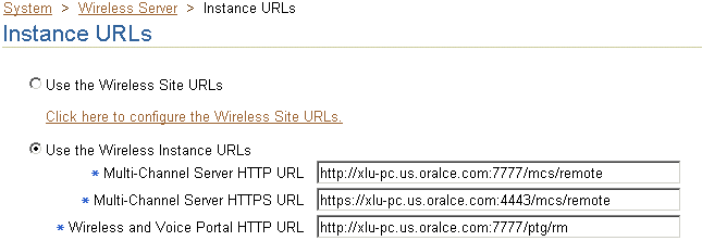
If you access the System Manager in the integrated mode (that is, through the Oracle Enterprise Manager Application Server Control as described in Section 3.2.2), then the Use the Wireless Instance URLs option is selected by default. With this option selected, the Wireless server uses the URLs defined on this page, which are populated by the post-installer to enable Wireless to work out of the box.
After completing the installations for each Wireless server on the Wireless site, you then configure the URLs for the Wireless site as virtual URLs and then select the Use the Wireless Site URLs option for each of the Wireless servers. When upgrading the Wireless site, you select Use the Wireless Instance option for each server until all of the servers on the Wireless site have been upgraded. See Section 3.6.1.1 for information on setting the URLs for the Wireless site.
As in the integrated mode, the Use the Wireless Instance URLs option is selected by default if you access the System Manager in the standalone mode (as described in Section 3.2.1).
After completing the standalone installation, you define the local URLs for all the Wireless services.
The instance URLs include those described in Table 3-2.
From the Home page of the System Manager, you can manage the wireless processes on the local middle tier. There are two types of wireless processes:
When you access the Home subtab, the Web-based applications display the following types of OC4J applications running in Wireless OC4J instance, with name and status information:
If the application name appears as a link, then you can access a detail page that displays the application's performance information. You can start or stop all the Web-based applications by clicking the Start OC4J Instance or Stop OC4J Instance buttons.
The standalone processes display the following types of Wireless processes by name, status and enabled flag:
By selecting a process, you can start or stop it as well as enable or disable it. Clicking Add Process invokes a two-step wizard that enables you to create a new process by first selecting the process type and entering the basic information about the process (such as the name) and then entering information specific to the process type. You can also select an existing process and delete it.
From the detail page, which you access by clicking the process name link, you can configure, or view the detail status and performance information of a standalone process. You can also start or stop the process at the process from this page.
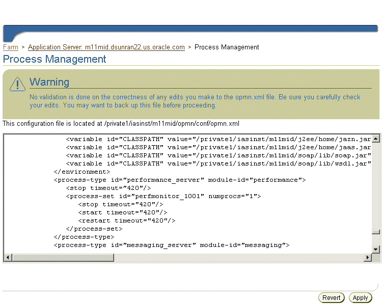
By default, the timeout to start or stop a standalone process is 420 seconds. You can adjust this value by updating opmn.xml directly by using the Process Management page. You invoke this page (Figure 3-12) from the Process Management link on the application server page in the Enterprise Manager in integrated mode. All of the Wireless standalone processes are listed under the Wireless component in opmn.xml.
You configure the notification applications running in the process, and view their performance regarding notifications that are processed and sent, subscribers to the notifications, and errors.
You specify the components which process the notification events.
You configure the data feeders running in the process.
You configure the driver instances running in the process, which determine what messaging services are provided. You can also view the server performance, such as the sending processing time, receiving response time, number of messages sent, for each delivery type.
For the messaging server to function, you must configure the messaging server drivers at the site level and the driver instances at the server process level.
Drivers are defined at site level under the Messaging process type. Each driver configuration includes category, capability (Send, Receive or Both), and driver class. For more information, see Section 3.6.2.5.
You specify the driver instances at Messaging Server process level. Each driver instance is based on a site driver. Because you add the values for the driver class parameters, you can create multiple driver instances based on the same driver; different driver instances can use the same class to send and receive messages, even though they have different parameter values. For example, two email driver instances can use different email servers. The attributes of a driver instance are as follows:
To update the driver instance, you select the driver instance from the Messaging Server process detail page and then click Edit.
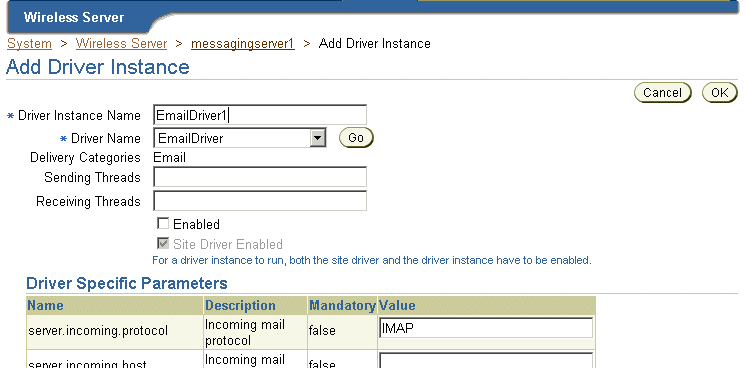
To create a driver instance, you use the Add Driver Instance page (Figure 3-13), which is invoked by clicking the Add Driver Instance button in the process detail page. You then select the site driver on which to base the new driver instance. Wireless retrieves the class parameter list from the site driver and populates the values for the new instance, which you can update. In addition to the class parameter values, Wireless also retrieves the site-enabled flag information as well as the number of sending and receiving threads which are based on the capability of the site driver.
If you base a driver instance upon a driver whose parameters have changed, for example, from the addition of a new parameter with default value or the removal of an obsolete parameter, then Wireless reflects these changes in the table listing the parameters in the editing page. In such a case, the table displays added parameters with a default value, but would not display an obsolete parameter that has been removed. After you create a driver, click Apply to save the new driver instance configuration.
|
Note: Changing the default parameter values for a messaging driver at the site level does not affect the driver instance. |
You can configure the number of working threads.
To configure a location event server process, you enter the number of positioning schedulers. Each location event server can have one or more positioning schedulers that process the location-based conditions. This setting specifies the number of positioning schedulers for each location event server.You base this setting on the system workload. If many location based-conditions are created and processed, then you should enter a number greater than 1 (such as 5 or 10).
However, if few location based-conditions are created and processed, one positioning scheduler will suffice. You can adjust this value according to the performance of the location event server.
The Response and Load section displays the following Wireless statistics, which are an overview of the process performance metrics based on the last 10 minutes for the local mid-tier:
The number of sessions which invoked applications in the last 10 minutes.
The average response time for applications invoked in the last 10 minutes
The average session duration for sessions invoked applications in the last 10 minutes
The total number of applications invoked in the last 10 minutes
The number of J2ME applications downloaded in the last 10 minutes
The number of notifications sent in the last 10 minutes
The number of messages sent in the last 10 minutes
The number of messages received in the last 10 minutes
On the Site Performance page (Figure 3-14), the Response and Load section displays the same type of performance data as the mid-tier, but the data is for the entire Wireless Site. You can also select the View Data options for the time interval of the performance data. The choices are:
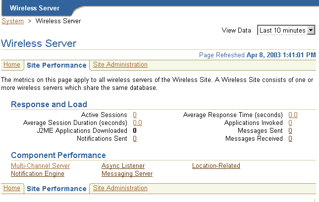
Clicking the links in the Component Performance section of the page enables you to view performance metrics within a selected time frame. The Performance page and the individual component performance pages each have a timestamp with a Refresh button, which enables you to reload the page to update the performance or status information.
The performance data over the designated time period is displayed for each process of the Wireless site:
The average application response time over the specified period.
The average session duration for session which invoked applications over the specified period.
The number of users who invoked applications over the specified period.
The number of applications invoked over the specified period.
The average number of application invocations for each session over the specified period.
The average number of application invocations for each user over the specified period.
Total number of errors for the specified period.
The performance data over the designated time period displays for each process of the Wireless site:
The total number of messages received for the specified period.
The average processing time per message for the specified period.
The average message queue size for the specified period.
The total number of applications accessed for the specified period.
The number of distinct users who accessed the site within the specified period.
The total number of errors for the specified period.
The performance data over the designated time period will be displayed for each individual process of the wireless site:
The total number of notifications processed over the specified time period.
The total number of notifications sent over the specified time period.
The total number of users who received notifications over the specified time period. A subscriber is a user who accesses a notification (and sets trigger conditions for a notification).
The total number of application invocations over the specified time period. In this version of Wireless, the notification message content is generated by invoking an application.
The total number of errors occurred over the specified time period.
The performance data are separated by client-side performance and server-side performance. The client performance is based on the designated time period for each individual delivery type of the wireless site:
The average time of a sending method. On the client side, a sending method is called to send a message. This time is the period from when the method is called to the time the method returns. When the method returns, the message is saved in a database persistently, but is not delivered.
The total number of times that the sending method is called by the client process. The sending method can be called once to send a message to a set of destinations.
The total number of successful calls, where a message is delivered to a proper gateway and its receipt is acknowledged. The client process can call the sending method many times to send many messages. Some of these requests fail, as in the case where a destination cannot be reached. Other requests could be undergoing processing.
The total number of all calls that are known to have failed.
The average time taken by the messaging system to deliver a received message to the client.
The server performance is based on the designated time period for each delivery type of each process of the wireless site:
The average time taken by messaging system to send a message, starting from the sending method called by the client, to the driver delivered the message to the proper gateway.
Once a transport driver receives a message, the message is passed to the transport system by an onMessage method. The response time is the time taken by the onMessage method. Once the onMessage returns, the received message is saved in a database for dispatching.
The total number of times the transport drivers call the onMessage call-back method.
The total number of received messages which are dispatched to, and are accepted by, the listeners. Among received messages, some may be in processing. Others may not have been dispatched to the listeners, or the listeners may have failed to process the dispatched messages.
The total number of received messages which failed to dispatch to a listener.
The location related performance metrics are measured by location-based service provider and by location event server.
These metrics display by Provider Name (the name of the application provider) and by Provider Type (the fully qualified class name associated with the provider) as follows:
The number of times an attempt was made to use this provider. It includes both successful and unsuccessful attempts.
The percentage of times that a hit resulted in a connection to the provider and the return of structurally acceptable information.
The average number of milliseconds that it took for a hit to have a successful or unsuccessful result.
These metrics display by process name (the name of a location event server) process as follows:
The average number of seconds that elapsed between the time a request was ready in the queue and the time the dequeuing of the request was finished.
The average number of seconds that elapsed between the time the dequeuing of the request was finished and the time the result was generated. The result can be a determination of whether the condition is satisfied or not, or it can be an error.
From the Site Administration page (Figure 3-15), you configure the Wireless system for the whole Wireless site; all of the Wireless servers use this common configuration. Also, from this page, you access functions to download or upload repository objects, and refresh the WebCache objects.
The timestamp on the Site Administration page displays the last time that the configuration data was loaded from the database. To update the data on the page, click the Refresh icon or update some configuration data. Otherwise, the timestamp the last time that the configuration data was loaded from the database.
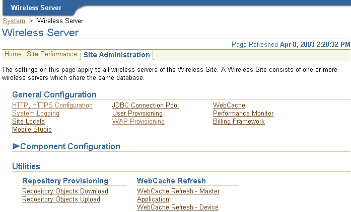
The General Configuration section contains the configurations generic for the wireless system.
The HTTP, HTTPS configuration page enables you to configure theWireless site's proxy server settings, URLs, and the Secure Socket Layer (SSL) certificates.
The proxy server section enables you to configure the proxy properties used by Wireless for HTTP protocol. If your network uses a proxy server, then you must set these properties to enable the proper functioning of such components as provisioning server, geocoding, and the XMS center.
|
Note: If your Wireless system does not use an HTTP proxy server, then you do not need to configure the proxy server properties. |
To configure the proxy server, specify the proxy server host, port and exception addresses. If you opt to require the proxy server to require authentication, then you must also provide the user name and password.
This page enables you to also define the URLs for the site. These URLs, which are listed in Table 3-3, can be used as the virtual URLs for Wireless servers. To enable the URLs defined in this page, select Use the Wireless Site URLs in the Instance URLs page, located on the Home page. For more information on the Instance URLs page, see Section 3.3.3. If you do not select this option, then the Wireless servers use their local URLs instead.
The SSL section enables you to configure your security certificates as either Base64 or PKCS#7-formatted certificate files to enable use of the HTTPS protocol. You can add, delete or update the certificated file name. Use the absolute file name. A Base64 certificate file is a text file, with the certificate information bounded at the beginning by '--BEGIN CERTIFICATE--' and at the end by '--END CERTIFICATE--'. A PKCS#7-formatted file is in binary code.
Pooling for JDBC connections improves resource utilization and reduces the connection establishment overhead when you access database. The JDBC Connection Pool page, invoked by selecting the JDBC Connection Pool hyperlink in the Site Administration page, enables you to configure the JBDC connection for the site, including:
For information, refer to Section 3.3.2.1.
The Site Locale page, invoked by selecting the Site Locale hyperlink in the Site Administration page, enables you to configure the locale and time zone for the site.
You can specify the default site locale and time zone. The default site locale can be selected from the list of all the supported locales of Wireless.Wireless ships with 29 supported locales which enable the translation of end-user messages into 29 languages. The administrator can add new locale or delete a locale using this page. For more information, see Section 15.2.4 in Chapter 15, "Globalization".
WebCache is an component used by Wireless to accelerate site performance by caching the content transformation.
Wireless performs transformations at two levels. At the first level of transformation, Wireless converts the adapter result, which is obtained as a result of the adapter pulling content from an external data source. The runtime adapters convert this into SimpleResult XML. Wireless performs a second transformation (that is, content transformation) when converting the SimpleResult XML into a device-specific markup language.
The WebCache configuration page enables you to set the cache policy. Table 3-4 lists these parameters:
For more information on WebCache, see Section 16.2.1 in Chapter 16, "Integrating Wireless with Other Components".
The User Provisioning page enables you to set the properties used by the Provisioning adapter.
Table 3-5 describes the properties for normal user provisioning.
A virtual user is a user who accesses a Wireless site, but does not register. When such a user accesses a Wireless site, Wireless detects the user and creates a virtual user account for that user.
Table 3-6 describes the properties for the virtual user provisioning.
You can create, edit, and delete WAP profiles using the Profile page, which you access by selecting the WAP Provisioning hyperlink. The Profile page displays a list of current WAP profiles. You can also add a WAP profile by defining the following parameters.
Table 3-7 describes the WAP provisioning profile parameters.
The Performance Monitor page enables you to configure the Wireless performance monitor, including the parameters described in Table 3-8.
The Billing Framework page enables you to configure the Oracle Application Server Wireless Billing Integration Framework, which provides an extensible and flexible framework to model billable services, capture billable action, and integrate with any external billing engine.
To enable the billing of all services, select Enable Billing. Billing is disabled by default.
To complete the billing enabling process, provide the implementation of two interfaces, the BillingDataCollector interface and the BillingDriver interface, and then configure them as the implementation classes.
|
Note:
The out-of-the-box implementation of the |
The Billing Collector Class, fetches all of the component-specific billing attributes and then plugs them into the service detail record (SDR), which encapsulates the billable action. The Billing Collector Class considers the following components: Runtime, Notification Server, Provisioning Server, and Messaging Server.
In addition, you define the Billing Provider Driver, the driver implementation provided at the customer end which communicates with the external billing system. To enter this value, you enter the full class with the package name, such as oracle.wireless.billing.SampleBillingDriver.
You can select, delete, or add the driver class initialization (init) parameters. If this billing driver implementation class expects initialization properties, then you add them as name-value pairs.
For more information about billing framework, refer to the Oracle Application Server Wireless Developer's Guide.
The Mobile Studio page enables you to configure Mobile Studio by defining the parameters described in Table 3-9.
|
Note: You must restart the Wireless server for the Mobile Studio configuration settings to take effect. |
For more information on Mobile Studio, see Section 6.2 in Chapter 6, "Administering Mobile Studio".
The component configuration section (Figure 3-16) contains the configurations specific to different Wireless subcomponents, which are represented as links. To access these links, you expand the Component Configuration section by clicking the plus (+) sign.

The Multi-Channel Server component includes the following configurations:
The Runtime page contains the configuration for runtime attributes, such as runtime session, and the object cache synchronization. Table 3-10 describes the runtime parameters, which you configure using this page.
For more information on the runtime, see the Oracle Application Server Wireless Developer's Guide.
Defining the parameters in the Object Cache Synchronization section of the page enables you to configure the thread pool, which handles the cache synchronization for messages. To configure the object cache synchronization, you define the following parameters:
The Device Configuration page enables you to add, edit, or delete HTTP header names that contain information for the device ID. You can also configure the Multi-Channel Server setup menu, with the following attributes:
On Folder page, you configure the folder sorting order and display by:
This Event and Listener page displays event options and available listeners. Using this page, you enable or disable event generation by selecting from among the event options and listeners. You also use the page to add, update or remove a listener for the request events, session events, or response events.
The Event and Listener page includes the following configuration options for events. You enable these options by selecting appropriate check boxes. If you do not select a check box, then the option is disabled (the default setting).
Table 3-11 describes the request, session, and response event options.
See the Oracle Application Server Wireless Developer's Guide for more information on event listeners.
You can change the hook implementation class for a selected hook using the Hook page.
Table 3-12 describes the hooks.
Multimedia adaptation services provide device-specific adaptation of images, ringtones, voice grammar, as well as audio and video streams. Wireless provides the default implementation for these services. To use different implementations, change the corresponding provider class name on Multimedia Adaptation Service configuration page.
See Oracle Application Server Wireless Developer's Guide for more information on multimedia adaptation.
You configure the following for the Async Listener component.
An access point is the address monitored by Async Listener is configured to listen, such as ask@mycompany.com for e-mail or 1234567 for SMS.
From the Add Access Point page (accessed by clicking the Add Access Point button in the Access Point page), you can use the Allowed to Access All Applications option to create two types of access points:
The Access Point page, invoked from Access Point link, displays a list of access points.You can add, delete or update an access point. Table 3-13 describes the attributes of the access points.
See the Oracle Application Server Wireless Developer's Guide for more information on PremiumSMS, ReverseCharge SMS and actionable message reply.
The Async Listener Configuration page enables you to configure the system settings for Async Listener, including the number of working threads, command format, application help, default application short name, and actionable message reply.
See the Oracle Application Server Wireless Developer's Guide for system configuration parameters for the Async Listener and for configuration parameters for actionable messages.
|
Note: The short name for replying to an actionable message must be unique among all the short name for Async application links. |
You must specify the Messaging Server client configuration for the Async Listener, because it is a client of the Messaging Server. You can add, delete or update the hooks used before or after sending a message (the pre-send and post-send hooks) or before or after receiving a message. Table 3-14 describes the parameters of the messaging server client.
You configure the following for the Notification Engine:
You can configure reply addresses of notifications for:
You can also configure the runtime settings related to location:
You can specify the Messaging Server client configuration for the Notification Engine, as a notification engine is one client of messaging server. Please refer to the discussion of Messaging Server Client in Section 3.6.2.3.
You configure the following for the Messaging component.
The Drivers page, invoked by clicking the Drivers link under Messaging Server in the Site Administration page, enables you to define a driver and its parameters. Table 3-15 lists the current drivers.
From this page, you can delete, edit, or create a messaging server drivers for the site. To create a new messaging server driver, you first click Add Driver and then define parameters listed in Table 3-16 in the Add Driver page.
Out of the box, Wireless provides 15 seeded drivers, which support all of the delivery categories. Each driver has a different set of class parameters. By default, all of these drivers are enabled. See the Oracle Application Server Wireless Developer's Guide for information on details of the drivers in the discussion of the transport component.
Clicking the Messaging Server Configuration hyperlink invokes the Messaging Server Configuration page, which enables you set the default configuration for the messaging server. Table 3-17 describes the messaging server configuration parameters.
The XMS Configuration page enables you to configure the settings for XMS Runtime and enable the XMS Center (XMSC), which adapts the content of a message to fit a given device. In addition, this page enables you to prioritize the device types for XMS message delivery.
Table 3-18 lists parameters that you define to set the XMS runtime.
The XMS Message Center (XMSC) supports MMS Center functionality out of the box, so that a device with MMS browser can receive notification messages and retrieve messages stored on the Wireless server through HTTP. It also supports MO (mobile-originated) messages to another phone and message storage and notifications for other delivery channels besides MMS. To configure the XMSC, you define the following two parameters:
XMS supports implicit device, or user addressing, by specifying the Wireless user name. XMS selects the best device for the user to receive messages, based on such factors as messaging content, application hints, and user preferences. If Wireless cannot send a message to one device, then XMS fails over to the next device in selection order and transforms the content for that device.
You define the values the Delivery Channel Settings section by specifying the priority (or failover) of the XMS message delivery types and by adding the appropriate reply addresses for the delivery types.
The location-related configuration includes the following
This page enables you to configure the format of location mark address. To do this, you select all of the attributes that you want to display for a location mark address. This configuration is used in Customization Portal.
You configure the following for the Notification Event Collector component.
For Wireless to process notification messages from Microsoft Exchange Server, accessing details to the Exchange Server needs to be configured in the system. For the details of each configuration parameter, refer to Chapter 17, "Integrating Wireless Notification with Microsoft Exchange".
You configure the following for the Provisioning Server component.
The Wireless Provisioning Server enables application providers to create and publish applications as well as serve content to the end-users when they download a selected application.
The download protocol differs based on the application type (such as a J2ME MIDlet or a ring-tone) and the line provisioning protocol. The appropriate provisioning driver, which you configure, enables the download. You can add new drivers or implement the customized functions of the existing drivers.
The actual upload and download processes can be monitored using hooks, which customers implement. The hooks are initialized using a singleton pattern. The hook method is given the user information, the application information and the content information. The hook implementation must provide a method such as:
public static <hookclass> getInstance()
In the Provisioning Server page, you define the class names for the pre-download hook, the post-download hook, and the deliverable content event listener.
Pre-Download Hook Class Name: This hook is invoked just before the user downloads the application. The hooks are initialized using a singleton pattern. The return code of the hook determines if the download can proceed.
The interface to be implemented is:
oracle.panama.rt.hook.ProvisioningPreDownloadHook
Post Download Hook Class Name: This hook is invoked once just after the user downloads the application and once after the user's device notifies the server of the application download. The provider can embed the billing action in either of these two invocations as appropriate.
The interface to be implemented is:
oracle.panama.rt.hook.ProvisioningPostDownloadHook
Deliverable Content Event Listener Class Name: This hook is invoked during content upload, update or delete.
The interface to be implemented is: oracle.panama.rt.event.DeliverableCtntEventListener
The driver implements the following interface: oracle.wireless.me.provisioning.ProvisioningDriver
You can add, delete or edit a driver. To add a driver, provide the driver class name, driver description and driver parameters, if any. Out-of-the-box, Wireless provides two driver implementations: the default provisioning driver (oracle.wireless.me.provisioning.DefaultProvisioningDriver) and the default JAR provisioning driver (oracle.wireless.me.provisioning.DefaultJarProvisioningDriver)These drivers are mapped to download J2ME MIDlets and JAR files, respectively.
You map the driver used for the appropriate application type and protocol configuration. Out of the box, the two drivers support SUN-OTA, and SUN-OTA_JAR protocols for J2ME applications. You can select the driver classes, which are used for the two protocols.
The utilities section contains the common utilities for the administrator to use.
|
Note: For the utilities to function:
|
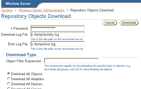
The Repository Objects Download page (Figure 3-17), invoked by selecting the Repository Objects Download hyperlink in the Utilities section of the Administration page, enables you to download repository objects. You can specify the types of repository objects to download. For example, you can download only adapters.
In addition, you can download by OID, and you can download applications by folder, or by user. You can also download all objects by user.
You can only download repository objects to a local file.
To download repository objects:
In the Windows dialog, specify the local XML file for the downloaded objects. Clicking Cancel after Download stops the download operation.
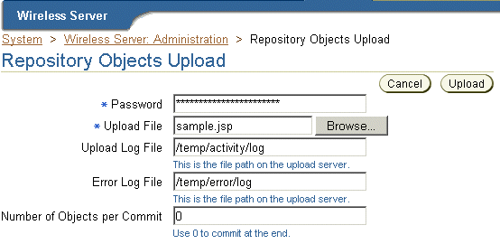
The Repository Objects Upload page (Figure 3-18), invoked by selecting the Repository Objects Upload hyperlink in the Utilities section, enables you to upload repository objects.
You can upload repository objects from a local file.
The upload function performs the following:
After each object type is successfully loaded, the uploading facility performs a commit unless you specify a different commit frequency. The commit includes all referenced objects (dependencies).
Wireless does not validate the XML file that you import into the repository using the upload facility. To avoid errors, work in an XML file that you have exported from the repository. This gives you a "known good" Repository XML framework for adding, removing, and modifying individual elements.
To upload repository objects:
|
Note: in integrated mode, you must be logged into SSO as a valid user with the Superuser's role before you can upload objects successfully. |
This utility enables you to explicitly purge the pages of a selected master application cached in WebCache. For example, you use this utility if you wish to clear stale content from a master application at a time other than the one set programmatically using the Service Manager.
To purge and refresh the pages for a selected master application, select the master application and click the Refresh Content button.
Using this utility, you can explicitly purge the pages of a specific device from the WebCache.
To purge and refresh the pages of a selected logical device, just select the device and click the Refresh Content button.
See Section 16.2.1 in Chapter 16, "Integrating Wireless with Other Components" for more information on WebCache.
|
|
 Copyright © 2003 Oracle Corporation. All Rights Reserved. |
|