| Oracle® Distributed Document Capture/Oracle® Document Capture Administrator's Guide Release 10gR3 E13871-01 |
|
 Previous |
 Next |
| Oracle® Distributed Document Capture/Oracle® Document Capture Administrator's Guide Release 10gR3 E13871-01 |
|
 Previous |
 Next |
This chapter contains information about the user interface for Oracle Document Capture. Screens for the following components are described in this chapter:
The following screens are used in Scan for ISIS administration.
"Manage Scan Profiles, Blank Page/Patch Code Detection Options"
"Manage Scan Profiles, Border/Halftone/Hole Removal Options"
Use this screen to select general settings for a scan profile.
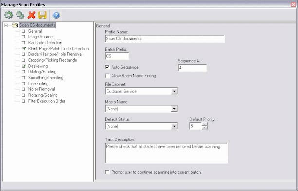
To display this screen, select Manage Scan Profiles from the Scanning menu, then select General in the side pane.
| Element | Description |
|---|---|
| Profile Name | Enter a name for the scan profile that describes the documents to be scanned using it. Users will see this name when selecting a scan profile. |
| Batch Prefix | Enter a prefix (optional). If you include a prefix, users will see this name in the Batch Scanning screen's Batch Name field after they select the scan profile. You can include up to eight characters. |
| Auto Sequence/Sequence Number | When Auto Sequence is selected, Scan names batches for users by combining the prefix with an auto sequence number that increments by one with each batch. Enter the number you want used to start naming batches in the Sequence # field. For example, if you enter INV as the batch prefix and 1 in the Sequence # field, the first batch would be named INV0000000000001, the second would be INV0000000000002, and so on. These options are available when a batch prefix is specified.
Note: To prevent conflicts between multiple Scan workstations, append a workstation identifier after the batch prefix (for example, CORRA, CORRB, and CORRC). |
| Allow Batch Name Editing | Select this field to allow users to enter a batch name in the Batch Scanning screen's Batch Name field prior to scanning. This option is available only if the Auto Sequence field is selected. If deselected (the default), users cannot enter batch names. Note that users can rename batches in the Batch Scanning screen after they are scanned, regardless of this setting. |
| File Cabinet | Select the file cabinet to which you want batches assigned. This field lists all file cabinets available. This is the file cabinet from which the batches will be indexed and then committed into your document management system. |
| Macro Name | If special scan customization is needed using a macro, select the macro in this field. |
| Default Status/Default Priority | Specify a status and/or priority to be assigned to batches when they are created.
Users can change the status or priority you select here. You define statuses in Capture Administration. |
| Task Description | Enter optional instructions for the scanning user.
Users will see this message in the Task Description field after selecting the scan profile in the Batch Scanning screen. (A task description is displayed to users only if you include one in this field.) For example, you may want to remind users to check that the documents are properly collated and that all staples have been removed before scanning. |
| Prompt user to continue scanning into current batch | This field determines what happens when the scanner's feeder tray runs out of paper.
If you select this field, users will be given the choice to continue scanning into the current batch when they add more paper to the scanner. If deselected (the default), the batch is completed and the user must click Begin Scanning again to start a new batch. |
Use this screen to configure a scanner or import source for the profile and to specify how images are stored in Capture.
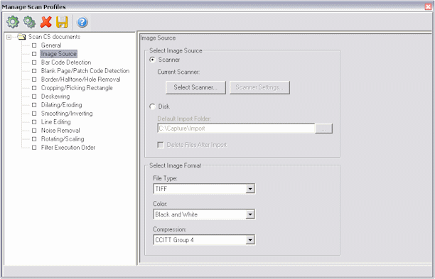
To display this screen, select Manage Scan Profiles from the Scanning menu, then select Image Source in the side pane.
| Element | Description |
|---|---|
| Scanner | Select this option to scan images using a selected scanner. Once a scanner is selected, its name is displayed after Current Scanner. |
| Select Scanner | Choose a scanner from a list of scanners for which you have ISIS drivers installed. You can also add a scanner, specifying its driver location.
Note: For document imaging scanners, most manufacturers provide the ISIS drivers on a CD shipped with the scanner. It is recommended to check the manufacturer's Web site for update drivers. Typically, the ISIS drivers are installed using a separate installation program. |
| Scanner Settings | Click this button to configure scanner settings. Available settings depend on the selected scanner. See the documentation that came with the scanner for more information. |
| Disk | Select this option to import images from a specified folder rather than scan them. When users click the Begin Scanning button in the Batch Scanning screen, a standard file dialog box displays, prompting them to select files to import. |
| Default Import Folder | Enter the path where the images are located. Users can change this location when importing files. |
| Delete Files After Import | Select this field to delete images from the import folder as they are imported. |
| File Type | Select the format in which you want images stored. You can choose TIFF (default), JPEG, PCX, or BMP. Because files are larger when stored in PCX and BMP formats, TIFF is recommended for black and white documents and JPEG is recommended for color documents.
Note: This setting affects the format in which images are stored in Capture's batch folder. Using commit profile options, you can output images in a different format when committing them, as described in "Commit Profile Settings Screen". |
| Color | Choose the color depth you want used to store images. The color options available depend on your File Type field selection (described above). Black and White images are significantly smaller than grayscale or color images, but typically display less detail. |
| Compression | Choose a compression method for images. Image compression substantially reduces file size; uncompressed images can exceed 1MB. The compression options available depend on your File Type and Color field selections (described above).
Note: Although listed as an option, Oracle I/PM does not support WANG JPEG compression when specifying a File Type of TIFF. To scan TIFF images with JPEG compression, use Oracle Document Capture Scan for Adrenaline. |
If your scanner has an imprinter/endorser, use this screen to configure automatic imprinting of images as they are scanned.
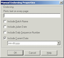
To display this screen, click the Scanner Settings button from the Image Source options in the Manage Scan Profiles screen. In the Scanner Settings dialog box, select Manual, and click Configure.
| Element | Description |
|---|---|
| Prints text on every page | Enter the text you want displayed on each document page. |
| Include Batch Name | Include the batch's assigned name on each document page. |
| Include Julian Date | Include the scan date and time, expressed as a Julian date, on each document page. |
| Include Daily Sequence Number | Include a counter number that increments by one for each batch, restarting each day. |
| Include Current Date | Include the current date on each document page, displayed using the selected format. |
Use this screen to specify whether bar codes are detected during scanning and how they are decoded. The bar code filter can detect a virtually unlimited number of bar codes on a page. For more information, see "Bar Code Detection".
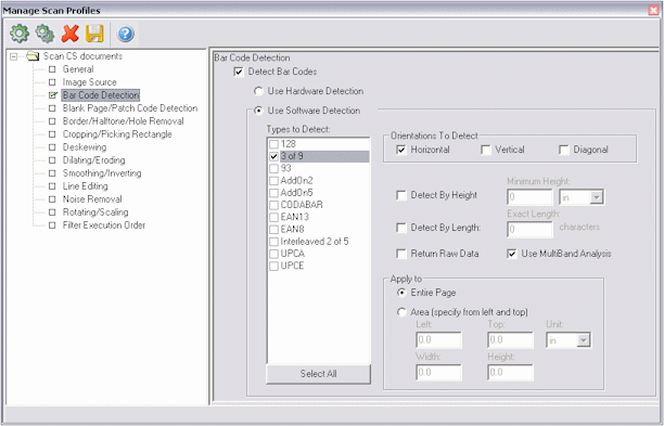
To display this screen, select Manage Scan Profiles from the Scanning menu, then select Bar Code Detection in the side pane.
| Element | Description |
|---|---|
| Detect Bar Codes | Select this field if you want bar codes detected. |
| Use Hardware Detection/Use Software Detection | Some scanners have bar code detection built into them. If this is the case, select Use Hardware Detection. Otherwise, select Use Software Detection to enable Scan to detect them.
(Skip the remaining steps if using hardware detection.) |
| Types to Detect | Select the types of bar codes you want Scan to detect.
You can select as many types as you want in the Types to Detect field. Click the Select All button to select all bar codes listed. The fewer types you select, the faster images are processed. |
| Orientations to Detect | Select the orientations of the bar code as seen on the scanned paper.
Selecting all three orientations (Horizontal, Vertical and Diagonal) is recommended, as the scanned image may be skewed. |
| Detect by Height, Minimum Height | Specify the minimum height for bar codes (if known).
To increase detection speed, reduce the amount of the page that is searched using the Detect by Height and Minimum Height fields. Specify the minimum height in the left field and the unit in the right field (inches, centimeters or pixels). For example, if you enter 2 in the Minimum Height field, Scan for ISIS searches for bar codes every 2 inches of the page. Bar codes smaller than the specified minimum height may be ignored; for example, a 1 inch bar code might lay in between the 2 inch gap described in the example above. |
| Detect by Length | Specify the number of characters in the bar codes to detect (if known).
To increase detection speed and accuracy, select the Detect by Length field and enter the exact number of characters that comprise the value of the bar code. Detected bar codes that do not match that length are ignored. |
| Return Raw Data | Select this field to return any special characters in bar code values.
Bar codes sometimes contain extra characters as part of their symbology. For example, the Code 39 symbology contains an asterisk at the beginning and end of its bar codes. By default, this diagnostic option is deselected. |
| Use MultiBand Analysis field | Select this field if poor quality images will be scanned using this profile. In general, this setting is recommended to improve recognition of bar codes.
Selecting this field may increase processing time, but is usually not noticeable. |
| Apply to | Specify the image area on which you want bar codes detected.
Choose Entire Page to examine the whole page or Area to specify a particular area on the image. If you select Area, choose a unit of measurement in the Unit field and specify the area from the left and top in the Left, Top, Width, and Height fields. Specifying the bar code's location on the scanned page will increase performance and reduce processing time. |
Use this screen to set Scan to detect patch codes and detect and remove blank pages during scanning. For more information, see "Blank Page and Patch Code Detection".
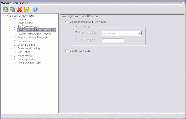
To display this screen, select Manage Scan Profiles from the Scanning menu, then select Blank Page/Path Code Detection in the side pane.
| Element | Description |
|---|---|
| Page is Blank If | Select this field to detect and remove blank pages using the blank page method. Specify how much noise is allowed for a page to be considered blank. You can choose:
|
| Byte Threshold | Select this field to detect and remove blank pages by byte threshold. Scan for ISIS will delete pages whose file size is less than or equal to the threshold value you specify in this field. For black and white (200 x 200 DPI images), the recommended value is 1500; at this setting, the application can usually differentiate between a blank separator page and a page with a small amount of text. However, you will need to conduct scan testing to determine the value required. |
| Detect Patch Codes | Select this field to detect patch codes.
If you encounter problems detecting patch codes, try improving pages' image quality using the following filters. Be sure to run these filters before the bar code detection filter; for details about filter order, see "Manage Scan Profiles, Filter Execution Order Options".
|
Use this screen to set Scan to remove black borders, halftones and holes from images during scanning. The filter looks for objects that resemble punch holes around the edges of the image. It does not remove objects that resemble punch holes from other areas of the image. For more information, see "Border, Halftone, and Hole Removal".
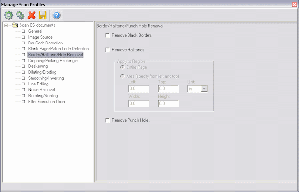
To display this screen, select Manage Scan Profiles from the Scanning menu, then select Border/Halftone/Hole Removal in the side pane.
| Element | Description |
|---|---|
| Remove Black Borders | Select this field to remove borders around image edges after scanning. The filter removes borders around image edges by changing them to white. |
| Remove Halftones | Select this field to remove a background or graphics object from images. |
| Apply to | Specify the image area from which you want halftones removed.
Choose Entire Page to examine the page or Area to specify a particular area on the image. If you select Area, select a unit of measurement in the Unit field and specify the area from the left and top in the Left, Top, Width and Height fields. |
| Remove Punch Holes | Select this field to detect and remove punch holes from image edges. |
Use this screen to set image margins and to add or remove white space around image edges. For more information, see "Cropping and Picking Rectangles".
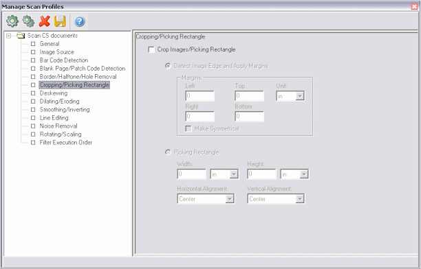
To display this screen, select Manage Scan Profiles from the Scanning menu, then select Cropping/Picking Rectangle in the side pane.
| Element | Description |
|---|---|
| Crop Images/Picking Rectangle | Select this field if you want images cropped. |
| Crop Images | To crop images based on an image edge, select the first crop mode and select settings.
Choose Detect Image Edge and Apply Margins if you want Scan to detect the image's edges and apply a specified amount of white space around images.
|
| Picking Rectangle | Select the radio button to capture only a portion of a scanned image.
|
Use this screen to straighten skewed images. You can either rotate images a specified number of degrees or set Scan to detect the skew angle and rotate the image to correct it. For more information, see "Deskew".
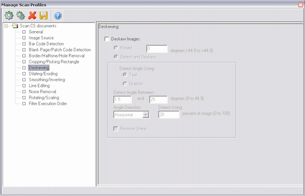
To display this screen, select Manage Scan Profiles from the Scanning menu, then select Deskewing in the side pane.
| Element | Description |
|---|---|
| Deskew Images | Select this field to deskew images. |
| Rotate/Detect and Deskew | Select a deskew mode.
|
| Detect Angle Using | Specify whether you want to use graphics or text to detect the skew angle., choose Text to detect the skew angle using letter-like objects, or Graphics to detect the skew angle using graphics objects, tables and black areas with white text.
Note: If images contain both text and graphics areas, decide which type of object you want used to detect the skew angle. Choose Graphics for images that contain large black areas, and choose Text for images that primarily contain text, with some tables and lines. Note: To remove shearing effects from images, choose Graphics and select the Remove Shear field. |
| Detect Angle Between | Specify the minimum and maximum skew angle to detect.
You can specify a range between 0 and 44.9 degrees. Enter the number of degrees in the minimum and maximum fields. An image's skew will be corrected only if it falls in the specified range. |
| Angle Direction | Specify the direction in which you want the skew angle measured.
The angle is measured between the image's edge and the Horizontal or Vertical axis. You can also measure the skew angle in Both directions. Note that the Remove Shear option will be disabled if Both is chosen. |
| Detect Using | Specify how much of the image you want examined for the skew angle.
In the Detect Using field, enter the percentage of the image area you want used to detect the skew angle. You can enter a number between 1 to 100. The default is 20, which specifies that 20% of the image area is used. Note that the larger the percentage you specify, the longer the processing time. |
| Remove Shear | Select this field to remove shear from images. See "Remove Shear".
Note: The Angle Direction field must be set to Vertical or Horizontal for the Remove Shear option to work. The Remove Shear setting is disabled if the direction is set to Both. |
When the Remove Shear field is deselected, Scan removes the rotational skew from images. This is needed when the connecting edges of skewed image data maintain a 90 degree angle, and Scan can correct the skew by simply rotating them.
When the Remove Shear field is selected, Scan removes the shearing skew. This is needed when the connecting edges of skewed image data do NOT maintain a 90 degree angle.
|
Note: The Direction field must be set to Vertical or Horizontal for the Remove Shear option to work. The Remove Shear setting is disabled if the direction is set to Both. |
Use this screen to either expand the area of black objects on images (Dilate filter) or trim the area of black objects (Erode filter). For more information, see "Dilating and Eroding".
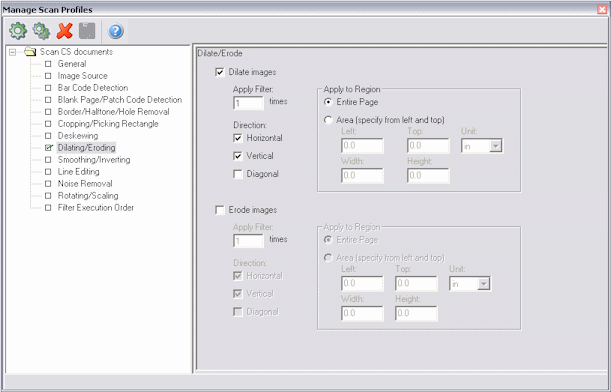
To display this screen, select Manage Scan Profiles from the Scanning menu, then select Dilating/Eroding in the side pane.
| Element | Description |
|---|---|
| Dilate Images | Select this field if you want images dilated, or the Erode Images field if you want images eroded.
The dilating or eroding options become available. |
| Apply Filter | Enter the number of times you want the dilation or erosion filter run.
The default is 1. The dilation filter expands the area of black objects. The erosion filter removes details from images. Setting this value to more than 1 for either filter can cause significant portions of image content to be lost. |
| Direction | Choose the direction(s) in which you want dilation or erosion performed on images.
You can choose Horizontal, Vertical or Diagonal. The default value is Horizontal and Vertical, which performs dilation or erosion in both the horizontal and vertical directions. |
| Apply to | Specify the image area you want dilated or eroded.
Choose Entire Page to dilate or erode the page or Area to specify a particular area on the image. If you select Area, select a unit of measurement in the Unit field and specify the area from the left and top in the Left, Top, Width and Height fields. |
Use this screen to delete bumps and spurs from text characters or objects on images (Smoothing filter) and to invert images (Inverting filter). For more information, see "Smoothing and Inverting".
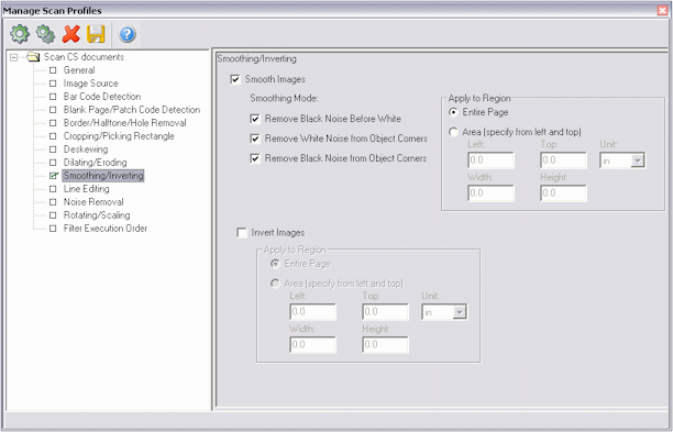
| Element | Description |
|---|---|
| Smooth Images | Select this field if you want images smoothed. |
| Smoothing Modes | Select one or more modes.
|
| Invert Images | Select this field if you want images inverted. |
| Apply to Region | Specify the image area you want smoothed or inverted.
Choose Entire Page to smooth or invert the page, or Area to specify a particular area on the image. If you select Area, select a unit of measurement in the Unit field and specify the area from the left and top in the Left, Top, Width and Height fields. |
To display this screen, select Manage Scan Profiles from the Scanning menu, then select Smoothing/Inverting in the side pane.
Use this screen to remove and optionally redraw straight lines on form-type images. For more information, see "Line Editing".
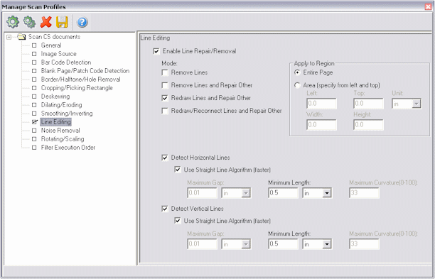
To display this screen, select Manage Scan Profiles from the Scanning menu, then select Line Editing in the side pane.
| Element | Description |
|---|---|
| Enable Line Repair/Removal | Select this field if you want lines edited. |
| Mode | Select one or more editing modes.
|
| Apply to | Specify the image area on which you want lines edited.
Choose Entire Page to edit lines on the page or Area to specify a particular area on the image. If you select Area, select a unit of measurement in the Unit field and specify the area from the left and top in the Left, Top, Width and Height fields. |
| Detect Horizontal Lines, Detect Vertical Lines | Select these fields to detect horizontal and/or vertical lines.
You must detect either horizontal or vertical lines. |
| Use Straight Line Algorithm | Select this field to optimize straight line processing.
This algorithm provides faster processing of straight lines longer than 100 pixels, and is particularly well-suited for forms and light paper. By default, this field is selected.
Note: When this field is selected, all other Detect Horizontal or Vertical Lines settings except the Minimum Length values are ignored.
|
Use this screen to set the Noise Removal filter to detect and remove noise. You do this by defining the maximum space an object can occupy within a specified area in order to be considered noise. For more information, see "Noise Removal".
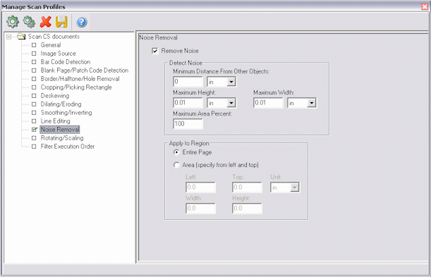
To display this screen, select Manage Scan Profiles from the Scanning menu, then select Noise Removal in the side pane.
| Element | Description |
|---|---|
| Remove Noise | Select this field to activate noise removal options. |
| Detect Noise | Specify how you want noise detected on images.
Scan removes noise objects that fit within the Maximum Height, Maximum Width and Maximum Area Percent field values.
|
| Apply to | Specify the image area form which you want noise removed.
Choose Entire Page to remove noise on the page or Area to specify a particular area on the image. If you select Area, select a unit of measurement in the Unit field and specify the area from the left and top in the Left, Top, Width and Height fields. |
Use this screen to rotate images in 90 degree increments (Rotating filter) or resize images to a specified width and height (Scaling filter). For more information, see "Rotating and Scaling".
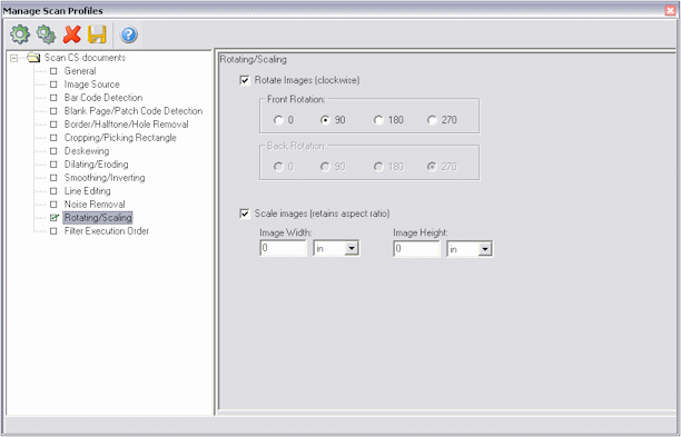
To display this screen, select Manage Scan Profiles from the Scanning menu, then select Rotating/Scaling in the side pane.
| Element | Description |
|---|---|
| Rotate Images | Select this field to rotate images. |
| Rotate | Choose how you want images rotated.
You can choose 0 (default), 90º clockwise, 180º clockwise or 270º clockwise. Note that you can specify a rotation for front and back sides, if needed. |
| Scale Images | Select this field to scale images. |
| Image Width, Image Height | Specify a new image width and height and select a unit of measurement (inches, centimeters or pixels).
Images will be resized so that they fit within the boundaries of the new width and height. If the width or height is larger than the scaled image area, then images are centered along that dimension and white margins are added. For example, if you start with an 8.5x11 inch image and want to scale it to 8.5x5.5 inches, then the image area will be scaled to 4.25x5.5 inches with 2.125 inches left and right white margins added to make the final scaled image 8.5 inches wide. |
Use this screen to change the order in which the filters are run or restore the default order.
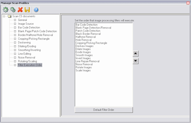
To display this screen, select Manage Scan Profiles from the Scanning menu, then select Filter Execution Order in the side pane.
| Element | Description |
|---|---|
| Up, Down | Click the Up button to move a selected filter up in the list, and the Down button to move it down. |
| Default Filter Order | Click this button to return the filters to the default order. |
The following screens are used in Scan for Adrenaline administration.
Use the General tab to set general settings for a scan profile.
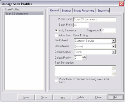
To display this screen, select Manage Scan Profiles from the Scanning menu and select the General tab.
| Element | Description |
|---|---|
| Profile Name | Enter a name for the scan profile that describes the documents to be scanned using it. Users will see this name when selecting a scan profile. |
| Batch Prefix | Enter a prefix (optional). If you include a prefix, scanning users see this name in the Batch Scanning screen's Batch Name field after they select a scan profile. You can type up to eight characters.
A batch prefix is typically used when the Auto Sequence field (see next step) is checked. Scan names batches for the user by combining the prefix with an auto sequence number that increments by one with each batch. For example, if you enter CORR as a prefix for correspondence, Scan might automatically name batches CORR000000000001, CORR000000000002, CORR000000000003, and so on. |
| Auto Sequence/Sequence Number | When Auto Sequence is checked, Scan names batches for users by combining the prefix with an auto sequence number that increments by one with each batch. Enter the number you want used to start naming batches in the Sequence # field. For example, if you enter INV as the batch prefix and 1 in the Sequence # field, the first batch would be named INV0000000000001, the second would be INV0000000000002, and so on. These options are available when a batch prefix is specified.
Note: To prevent conflicts between multiple Scan workstations, append a workstation identifier after the batch prefix (for example, CORRA, CORRB, and CORRC). |
| Allow Batch Name Editing | Select this field to allow users to enter a batch name in the Batch Scanning screen's Batch Name field prior to scanning. This option is available only if the Auto Sequence field is selected. If this field is deselected (the default), users cannot enter batch names at scan time. Note that users can rename batches in the Batch Scanning screen after they are scanned, regardless of this setting. |
| File Cabinet | Select the file cabinet to which you want batches assigned. This field lists all file cabinets available. This is the file cabinet from which the batches will be indexed and then committed into your document management system. |
| Macro Name | If special Scan customization is needed using a macro, select the macro in this field. |
| Default Status, Default Priority | Specify a status and/or priority to be assigned to batches when they are created.
Users can change the status and priority you select here. You define statuses in the Capture Administration screen. |
| Task Description | Enter optional instructions for the scanning user.
Scanning users will see this message in the Task Description field after selecting the scan profile in the Batch Scanning screen. (This field is displayed to users only if you include an entry.) For example, you may want to remind the user to check that the documents are properly collated and that all staples have been removed before scanning. |
| Prompt user to continue scanning into current batch | This field determines what happens when the scanner's feeder tray runs out of paper.
If you select this field, users will be given the choice to continue scanning into the current batch when they add more paper to the scanner. If this field is not checked (the default), the batch is completed and the user must click Begin Scanning again to start a new batch. |
Use this tab to configure a scanner or disk source and specify how images are stored in Capture.
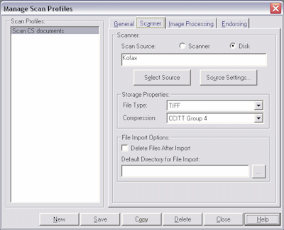
To display this screen, select Manage Scan Profiles from the Scanning menu and select the Scanner tab.
| Element | Description |
|---|---|
| Scan Source | Specify the scan source. After a scan source is selected, its name is displayed in this field.
Note: To enable image processing settings, you must configure a scan or disk source with image processing. |
| Select Source | Choose a scan or disk source. A source must be defined by the Kofax Source Manager (KSM) using the KSM (32-bit) icon from the control panel. Refer to Kofax documentation for instructions on setting up a scan or disk source, and configuring properties and advanced settings. |
| Source Settings | Click this button to configure scanner settings. Scan automatically detects the capabilities of the selected scanner and selects default values, which you can adjust. Available settings depend on the selected scanner. See the documentation that came with the scanner for more information.
In general, set your scanner settings so they accommodate most of the documents being scanned using the selected scan profile. Keep in mind that scanning users can override a profile's scanner settings without changing the profile, then select the profile again at any time to reload the default profile settings. |
| File Type | Select the format in which you want images stored. You can choose TIFF (default), JPEG, PCX, or BMP. Because files are larger when stored in PCX and BMP formats, TIFF is recommended for black and white documents and JPEG is recommended for color documents.
Note: This setting affects the format in which images are stored in Capture's batch folder. Using commit profile options, you can output images in a different format when committing them, as described in "Commit Profile Settings Screen". |
| Compression | Choose a compression method for images. Image compression substantially reduces file size; uncompressed images can exceed 1MB. The compression options available depend on your File Type field selections (described above). |
| Delete Files After Import | Select this field to delete images from the import directory as they are imported. |
| Default Directory for File Import | Enter the default path where the images are located. Users can change this location when importing files. |
Use the Image Processing tab to select precise settings to make images easier to read, reduce file sizes and improve processing. This section describes in detail image processing options you can select for scan profiles.
|
Note: Image processing options require a version of Kofax Adrenaline engine that supports image processing. |
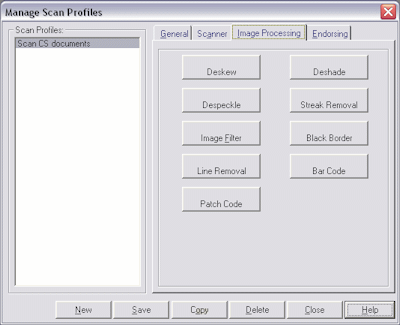
To display this screen, select Manage Scan Profiles from the Scanning menu and select the Image Processing tab. A light bulb displays next to options that are enabled for this profile.
Image processing options include:
Deskew is the process of straightening a crooked or skewed image.
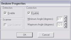
To display the Deskew Properties dialog box, select Manage Scan Profiles from the Scanning menu, select the Image Processing tab and click Deskew.
| Element | Description |
|---|---|
| Enable | Select this field to correct the angle of skewed images. |
| Minimum Angle | Select the minimum amount of skew that must be corrected.
For example, if the image is skewed 5 degrees and you select a minimum angle of 2 degrees, the skew is corrected. If the image is skewed less than the minimum angle value, no correction is performed. To specify the minimum angle, click the arrows or type the value. The value you can select depends on the setting for the maximum skew angle. Minimum Angle Example: If the maximum skew angle is set to 10 degrees, the highest allowable value for the minimum skew angle is 9.9 degrees. |
| Maximum Angle | Select the maximum amount of skew that must be corrected.
For example, if the image is skewed 10 degrees and you select a maximum angle of 15 degrees, the skew is corrected. If the image is skewed more than the maximum angle value, no correction is performed. To specify the maximum angle, click the arrows or type the value. The value you can select depends on the setting for the minimum skew angle. Maximum Angle Example: If the minimum skew angle is set to 15 degrees, the lowest allowable value for the maximum skew angle is 15.1 degrees. |
Tips For Deskewing Images
Follow these tips:
Both skew detection and skew correction must be enabled for images to be deskewed.
Correcting heavily skewed images can affect performance
The skew calculation requires a source image that has a horizontal and vertical flow, such as text or lines. A skew calculation for an image that consists mostly of lines with no horizontal or vertical flow (for example, a picture) can return an invalid skew angle.
The despeckle feature removes unwanted dots or speckles on an image.
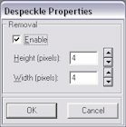
To display the Despeckle Properties dialog box, select Manage Scan Profiles from the Scanning menu, select the Image Processing tab and click Despeckle.
| Field or Button | Description |
|---|---|
| Enable | Select this field to enable the Despeckle filter. |
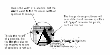
| Height, Width | Select the maximum height and width of a speckle to be removed
All speckles with a height and width less than or equal to the Height and Width settings are removed. You can select any value between 1 and 32 pixels. Even speckles with gaps are detected and removed. |
Tips For Despeckling Images
Follow these tips:
Set the Height and Width options to the appropriate values for your image. Using large values for these options could remove portions of your image that you want to keep.
Check your image to ensure that punctuation marks (such as commas, periods, and quotation marks) are not being removed. If they are, adjust the values of the Height and Width properties.
Use Image filters to enhance line edges, smooth characters, and remove background noise on an image.
To display the Image Filter Properties dialog box, select Manage Scan Profiles from the Scanning menu, select the Image Processing tab and click Image Filters. Select the Enable field to activate the selected filter.
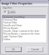
Image filters include:
Tips For Using Image Filters
Follow these tips:
Character Smoothing always has a positive effect on an image. You can use this filter in combination with any other image filter.
The combination of deshade, despeckle, line removal, and the Smooth and Clean image filter produces better results than using just the Smooth and Clean image filter. However, the Smooth and Clean image filter should not be used as an alternative to deshade, despeckle, and line removal.
The combination of deshade, despeckle, and the Smooth, Clean, and Preserve h&v lines image filter produces better results than using just the Smooth, Clean, and Preserve h&v lines filter. The Smooth, Clean, and Preserve h&v lines filter should not be used as an alternative to deshade and despeckle.
Thinning should only be applied to images that contain elements that are ballooned or blended together. Applying this filter to an image that does not contain such elements may cause the loss of important data.
Light Thicken should be applied to images that have been deshaded and despeckled. Using this filter may exaggerate background noise. The Light Thicken filter is less aggressive than the Thicken filter.
Thicken should be applied to images that have been deshaded and despeckled. Using this filter may exaggerate background noise. Thicken should only be applied to images that contain thin or light elements (such as images containing dot matrix characters or fax images). Applying this filter to an image that does not contain such elements may cause characters and lines to blend together.
Fill Line Breaks is recommended for use with images that contain lines. However, it may cause parallel lines that are separated by only one pixel to be merged. For images that contain parallel lines that are close together, the Fill Line Breaks and Preserve h&v lines filter should be used instead.
Fill Line Breaks and Preserve h&v lines is recommended for use with images that contain lines that are close together (separated by only one pixel).
|
Note: When using the image filters, it is recommended that you process a test image to determine the best settings for your file cabinet/application. The default settings, which have been calibrated for typical, real-world images, should work in most cases. If adjustments are necessary, they should be made carefully to achieve the desired results. |
This filter smooths characters and lines.

Features of the Character Smoothing filter:
No negative impact on the image.
Increases legibility.
Consistently reduces compressed file sizes by 10 to 15 percent.
This filter considers the color of the four perpendicular pixels of every pixel in the source image. If the majority of the four perpendicular pixels have the color opposite from the pixel's color, the color of the pixel is changed to match that of its neighbors.
This filter thins characters and lines and may remove background noise.

Features of the Thinning filter:
May have a negative impact on the image.
Good for character separation (for elements that are ballooned or blended together).
May reduce compressed file size.
This filter thins down image elements by setting any black pixel to white if it is perpendicular or diagonally adjacent to at least one white pixel in the source image.
This filter thickens characters and lines and may exaggerate background noise.

Features of the Thicken filter:
May have a negative impact on the image.
Good for dot matrix characters or for enhancing fax images (for thin or light elements).
May increase compressed file size.
This filter thickens image elements by setting any white pixel to black if it is perpendicular or diagonally adjacent to at least one black pixel in the source image.
This filter smooths characters, removes background noise, and may eliminate lines.

Features of the Smooth and Clean filter:
Usually has a positive impact on the image.
Increases legibility.
Increases OCR accuracy.
Consistently reduces compressed file sizes by at least 10 to 15 percent.
This filter is faster than using the Thinning filter followed by a Light Thicken filter, but has exactly the same effect. It sets any black pixel to white if it cannot be considered part of at least a 2x2 block of black pixels in the source image.
This filter fills in and smithies lines.

Features of the Fill Line Breaks filter:
May have a negative impact on the image because parallel lines close together may be merged.
May increase legibility.
May increase compressed file size.
This filter sets any pixel to black if it cannot be considered part of at least a 2x2 block of white pixels in the source image.
This filter smithies characters and lines and removes background noise.

Features of the Smooth, Clean + preserve h&v lines filter:
Usually has a positive impact on the image.
Increases legibility.
Increases OCR accuracy.
Consistently reduces compressed file sizes by at least 10 to 15 percent.
This filter is identical to the Smooth and Clean filter except that it preserves horizontal and vertical black line segments that are one pixel wide.
This filter fills in and smithies lines while maintaining the interline gap.

Features of the Fill Line Breaks + preserve h&v lines:
Can have a positive impact on the image because parallel lines close together are not merged.
Increases legibility.
May increase compressed file size.
This filter is identical to the Fill Line Breaks filter except that it preserves horizontal and vertical white line segments that are at least one pixel wide.
This filter thickens characters and lines and may exaggerate background noise, but is not as aggressive as the Thicken filter.

Features of the Light Thicken filter:
May have a negative impact on the image.
Good for dot matrix characters or for enhancing fax images (for thin or light elements).
May increase compressed file size.
This filter is a less aggressive version of the Thicken filter. It performs approximately half the thickening of the full Thicken filter.
This filter extracts an outline of all image elements.

Features of the Outline filter:
May have a negative impact on the image.
Decreases compressed file size.
Use the line removal feature to remove horizontal and/or vertical lines or to repair text that intersects the lines that are removed.
To display the Line Removal Properties dialog box, select Manage Scan Profiles from the Scanning menu, select the Image Processing tab and click Line Removal.
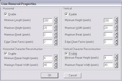
| Element | Description |
|---|---|
| Horizontal | Select this field to remove horizontal lines from images.
|
| Vertical | Select this field to remove vertical lines from images.
|
| Horizontal Character Reconstruction | Select this field to help rebuild and repair text that intersects with removed lines.
|
| Vertical Character Reconstruction | Select this field to help rebuild and repair text that intersects with removed lines.
|
Tips For Removing Horizontal Lines
Follow these tips:
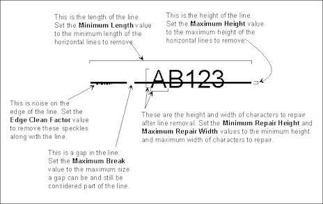
Set the Minimum Length parameter to a large enough value so that text objects (such as the horizontal bar of the letter T) are not mistaken for horizontal lines. Setting a larger value also allows the software to work faster because many objects, such as text, can be ignored when searching for lines.
Set the Maximum Break parameter to a maximum value of 2 or 3 pixels at 200 dpi. Doing this helps prevent text from being considered a line.
Tips For Removing Vertical Lines
Follow these tips:
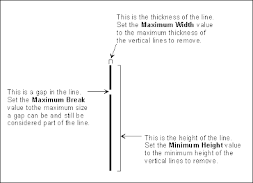
Set the Minimum Height parameter to a large enough value so that text objects (such as the vertical bar of the letter T) are not mistaken for vertical lines. Setting a larger value also allows the algorithm to work faster because many objects, such as text, can be ignored when searching for lines.
Set the Maximum Break parameter to a maximum value of 2 or 3 pixels at 200 dpi. Doing so helps prevent text from being considered a line.
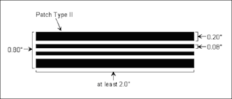
All patch codes are made up of narrow and wide bars:
The narrow bars must be 0.08 inch in height.
The wide bars must be 0.20 inch in height.
The entire patch code must be 0.80 inch in height.
The entire patch code should be at least 2.0 inches in width.
|
Note: As an alternative to using patch codes, you can specify that a bar code be interpreted as a patch code, as well as being used as a bar code. This might be useful, for example, if there is always a bar code on the first page of each document. For more information, see the Interpret Bar Code as Patch Code field described in "Bar Codes Properties". |
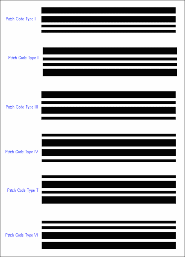
Patch Code Types
|
Note: In compliance with the patch code specification for duplex scanning operations, patch codes are only detected on the front side of a page. Any patch codes on the backside of a page are ignored. |
Patch Code Properties (Advanced)
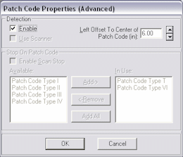
To display the Patch Code Properties (Advanced) dialog box, select Manage Scan Profiles from the Scanning menu, select the Image Processing tab and click Patch Code.
| Element | Description |
|---|---|
| Enable | Select this field to enable the patch code detection feature. |
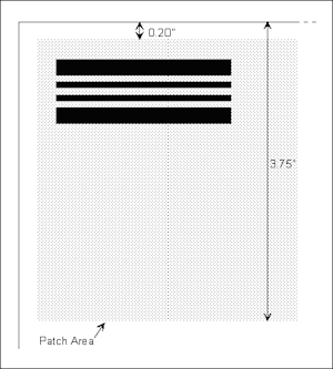
| Left Offset to Center of Patch Code | Select a value from the left edge of the page that defines a point that falls near the center of the patch code. The offset value allows the patch code detection feature to quickly locate the patch code on the page. This offset can be any value between 0 and the maximum page width, in inches. A value of 0 specifies searching anywhere in the horizontal direction for a patch code. To be detected, patch codes must be positioned correctly on the page (see below):
|
| Stop on Patch Code | In addition to being used as document separators, patch codes can be used as triggers to stop the scanner while scanning, if your scanner supports this feature. Using patch codes to stop the scanner can be useful for changing scanner settings on-the-fly between batches.
Note: This feature is not available when processing images from disk. To use patch codes to stop the scanner, patch code detection must be enabled. The scanner is stopped when the patch code is detected, allowing the scanner settings to be changed. Patch codes are read before any other image processing takes place. Patch code detection takes place twice: once before image processing occurs and once after. If the patch code is not found before image processing occurs, the scanner does not stop. |
| Enable Scan Stop | Select this field to enable the patch code trigger feature. |
| Available | Displays all of the patch code types that can be used to stop a scanner. |
| In Use | Displays all of the patch code types that are currently configured to stop a scanner:
|
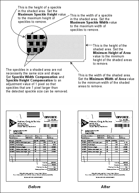
Shaded areas on an image are made up of patterns of black speckles. Deshading removes the speckles that make up the shaded area while preserving the text inside the shaded area. Removing shaded areas helps to reduce compressed file sizes.
To remove shaded areas from an image, define the characteristics of the shaded areas you want to remove by specifying their height and width and the size of the speckles in them. Any text that displays within a shaded area is preserved.
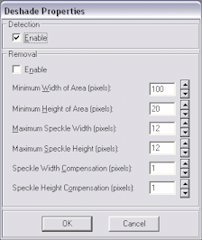
To display the Deshade Properties dialog box, select Manage Scan Profiles from the Scanning menu, select the Image Processing tab and click Deshade.
| Element | Description |
|---|---|
| Enable | Select this field to remove shaded areas on an image. |
| Minimum Width of Area | Enter the minimum width in pixels of the shaded area on an image to be removed. |
| Minimum Height of Area | Enter the minimum height in pixels of the shaded area on an image to be removed. |
| Maximum Speckle Width | Enter the maximum width in pixels of a speckle within a shaded area. |
| Maximum Speckle Height | Enter the maximum height in pixels of a speckle within a shaded area. |
| Speckle Width Compensation | Enter a positive or negative horizontal adjustment value for the size of a speckle in pixels to remove when deshading an image. This adjustment value accounts for horizontal differences in speckle sizes within a shaded area. The adjustment value is added to the detected Speckle Width of the speckles in the shaded area to determine which speckles are to be removed.
Set this property to 1 to remove all speckles in the shaded area up to the detected Maximum Speckle Width plus 1 pixel. Conversely, set this property to -1 to remove all speckles in the shaded area up to the detected Maximum Speckle Width minus 1 pixel. For example, if the deshade algorithm detects a shaded area with a speckle size of 3, it removes speckles in the shaded area that have a width less than or equal to 4. |
| Speckle Height Compensation | Same as the Speckle Width Compensation setting, but you set the height instead of the width. |
Tips For Deshading
Follow these tips:
Set the Minimum Width of Area and Minimum Height of Area as large as possible without making the values larger than the smallest shaded area you want to detect. For example, if all shaded areas you want to remove are 5 inches wide and 2 inches tall, you should set Minimum Height of Area to 1.5 inches and Minimum Width of Area to 4.5 inches. Setting these values too small (less than 1 inch) could cause the deshade algorithm to detect text as shaded areas.
Leave the Maximum Speckle Width and Maximum Speckle Height at their default values. The defaults should be sufficient to detect most shaded areas.
Set the Speckle Width Compensation and Speckle Height Compensation to 0 (the default) or 1. The defaults should be sufficient for most speckles in the detected shaded areas.
Use the Streak Removal options to remove streaks from images.
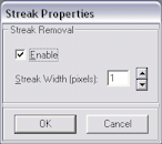
To display the Streak Properties dialog box, select Manage Scan Profiles from the Scanning menu, select the Image Processing tab and click Streak Removal.
| Element | Description |
|---|---|
| Enable | Select this field to activate the streak removal feature. The streak removal feature processes each horizontal scan line of the image to detect runs of black pixels. Any series of black pixels less than or equal to the streak width are removed. Although streak removal processes the image from left to right, its main purpose is to eliminate vertical streaks. |
| Streak Width | Select the width of the streaks to remove. Any vertical lines with a width less than or equal to the value of the Streak Width setting are removed. For typical images, set the Streak Width to a value of 1 or 2 pixels. Since streak removal looks for any series of like pixels less than or equal to the streak width, setting the width too high could have an adverse effect on the image by eliminating data. |
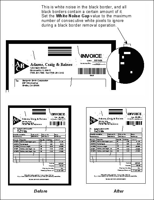
The black border removal feature transforms any black borders to white, thereby producing a cleaner image for processing and readability, and reducing compressed file sizes.
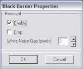
To display the Black Border Properties dialog, select Manage Scan Profiles from the Scanning menu, select the Image Processing tab and click Black Border.
| Element | Description |
|---|---|
| Enable | Select this field to enable the black border removal feature. |
| Crop | Adjusts the image size (height and width) after black border removal. |
| White Noise Gap | Select a value, in pixels, from 0 to 10 for the White Noise Gap. |
White Noise Gap
As soon as it detects a white pixel, Scan uses the following logic to determine whether the white pixel is part of white noise in the border or the edge of the image:
If a series of white pixels in the black border is less than or equal to the value of the White Noise Gap, it is considered white noise. In this case, the white noise is ignored and the black border removal process continues.
If the number of consecutive white pixels is greater than the White Noise Gap, it is considered the end of the border and the black border removal process stops.
For best results when removing a black border, make sure you do not set the value of the White Noise Gap too low. This prematurely stops the black border removal process. If any portion of the black border is not removed, increase the value of the White Noise Gap.
Use the Bar Code setting to detect bar codes on an image and convert them to their ASCII equivalents. During a bar code recognition operation, the image is searched for possible bar codes. If a potential bar code is found, it is examined to determine if it satisfies all of the requirements as outlined in the settings. For example, the physical characteristics of the bar code, such as bar code type and minimum number of characters in the bar code are checked against the settings.
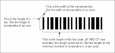
Bar Size
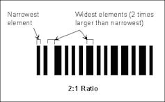
2 to 1 Ratio
Search Direction
Quality

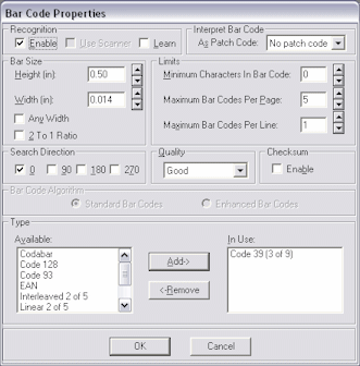
To display the Bar Code Properties dialog box, select Manage Scan Profiles from the Scanning menu, select the Image Processing tab and click Bar Codes.
| Element | Description |
|---|---|
| Recognition | Specify how you want bar codes recognized.
|
| Interpret Bar Code as Patch Code | Allows you to specify that the detection of a bar code should trigger a patch code as well as return the bar code value. This might be useful, for example, if there is always a bar code on the first page of each document. |
| Bar Size | Specify the bar code's size. (Refer to the Bar Size illustration in this section.)
|
| Limits | If multiple bar codes exist on an image, you can specify the maximum number of bar codes to be returned. Bar codes are returned in the order they are found.
|
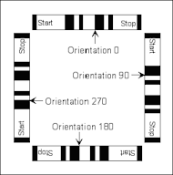
| Search Direction | The bar code driver searches for bar codes in a linear fashion, probing the search area for potential bar codes. (Refer to the Search Direction illustration in this section.) For horizontal bar codes with an orientation of 0, for example, it works down the image starting on the left edge and probing toward the right edge. For vertical bar codes, it works across the image starting on the top edge and probing top to bottom. Bar codes can be orientated on an image in four general directions as described below. If you select all options, a search for bar codes in all orientations is performed.
Note: Searching for bar codes in all orientations may reduce scan performance. |
| Quality | The quality of a bar code refers to the condition of the bar code elements on an image. (Refer to the Quality illustration in this section.) For example, sometimes the bar code elements are well defined with the black bars being clearly delineated and very little noise existing on the image. Other times, the black bars are too light or noise exists in the bar code's quiet zone. These factors can affect the bar code driver's accuracy rate. You can indicate the quality of the bar codes being read by setting the quality to Good, Normal, or Poor.
|
| Checksum | If the bar codes contain a checksum, select the Enable field to cause the bar code reader to automatically verify the checksum. Some bar codes contain a checksum character. The checksum is usually the last character in the bar code, and is used by the bar code recognition driver to determine the validity of the bar code. (The checksum is only used to determine if a bar code is valid; it is not returned as part of the bar code data.) Not all bar code types support a checksum character. Of the bar code types that do, some support a mandatory checksum, while others support an optional checksum.
Note: Optional checksum verification only works with these bar code types: Code 39, Interleaved 2 of 5, and Linear 2 of 5. It is ignored for all other bar code symbologies. |
| Type | The Type group displays a list of the available bar codes and those that are currently in use.
|
Tips For Improving Bar Code Recognition
Follow these tips:
Adjust the bar height and quality to increase the number of search probes. As the height is decreased, the number of probes is increased. Doing this allows more areas on an image to be probed.
Adjust the width setting.
Adjust the density setting for the scanner. If the bars appear too light, increase the density setting. If the bars appear too thick, decrease the density setting.
Adjust the dpi setting for the scanner. Scanning at a higher resolution usually improves the accuracy of the driver. Even a slight adjustment, from 200 to 240 dpi, for example, can make a difference.
When using a Bell+Howell ACE scanner, set the scan mode to Text/Line Art and the Sensitivity setting to S4. Using other ACE settings can cause the scanner to widen some bar codes in the direction the paper is moving or split some bar codes in two. Code 128 and Codabar bar code types are particularly susceptible to these problems.
Tips For Optimizing Bar Code Detection Speed
Follow these tips:
Increase the height of the search probe by adjusting the height and quality settings. The speed of the bar code driver increases proportionately. For example, if the search height is made twice as large, the bar code driver will be twice as fast.
Increase the height of the search probe by adjusting the height and quality settings. The speed of the bar code driver increases proportionately. For example, if the search height is made twice as large, the bar code driver will be twice as fast.
Specify only the required search directions. The bar code driver searches in all specified directions, even if no bar codes exist. For example, if all of the bar codes on an image are horizontal with an orientation of 0 degrees and you set all search directions, the bar code driver searches all directions.
Specify only those types of bar codes that you want to find. For example, if all the bar codes on an image are Code 128, don't force the bar code driver to search for Code 128 and Code 39.
Specify the minimum number of characters in a bar code. This allows the bar code driver to quickly dismiss ineligible objects.
Set the maximum number of bar codes on a line to as small a value as possible. This allows the driver to stop searching a line when the appropriate number of bar codes is read.
Set the maximum number of bar codes on a page to as small a value as possible. This allows the driver to stop searching on a page when the appropriate number of bar codes is read.
Use the Endorsing tab to select settings for endorsing (imprinting) document pages as they are scanned.
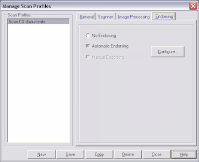
To display this screen, select Manage Scan Profiles from the Scanning menu and select the Endorsing tab.
| Element | Description |
|---|---|
| No Endorsing/Automatic Endorsing/Manual Endorsing | Select an endorsing option.
Note: This setting depends on the endorsing option your scanner supports. In addition, your scanner determines the available endorsing options. Refer to your scanner documentation for more information. |
| Configure | Click to configure automatic or manual options.
If you selected Automatic, the Automatic Endorser/Annotation Properties dialog box is displayed, described below. If you selected Manual, see the Endorser dialog box described below. |
Automatic Endorser/Annotation Properties
Use this dialog box to configure automatic endorsement properties.
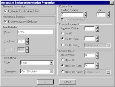
To display this dialog box, select Manage Scan Profiles from the Scanning menu, and select the Endorsing tab. Choose Automatic Endorsing and click Configure.
| Element | Description |
|---|---|
| Enable Automatic Annotation | Select this field to enable automatic annotation. Electronic annotation refers to a process in which the software adds a value to the image, but not the physical paper. |
| Enable Automatic Endorser | Select this field to enable automatic endorsing. Mechanical endorsing refers to a physical imprinter in the scanner. |
| Text Definition | Complete settings.
|
| Font Setting | Complete settings
|
| Counter Start | Complete settings
|
| Counter Increment | Complete settings
|
| Counter Reset | Complete settings.
|
Endorser
Use this dialog box to set manual endorsing options.
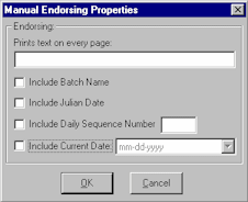
To display this dialog box, select Manage Scan Profiles from the Scanning menu, and select the Endorsing tab. Choose Manual Endorsing and click Configure.
| Element | Description |
|---|---|
| Prints text on every page | Enter the text you want displayed on each page. |
| Include | Select the fields corresponding to items you want displayed with the endorsement. For example, to include the date, select the Include Current Date field and select a date format from the field to its right. |
Index includes the following screens and dialog boxes:
Use this tab to select general settings for the index profile.
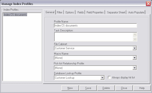
| Element | Description |
|---|---|
| Profile Name | Replace the default name of <Index Profile 1> by typing a descriptive name for the index profile. This name will be displayed to indexing users selecting a profile. |
| Task Description | Type instructions for the indexing user, who sees this message when selecting the index profile. |
| File Cabinet | Select a file cabinet. The file cabinet helps determine which batches are available for indexing. In addition, the file cabinet determines where the documents will be stored. |
| Macro Name | Select a previously created macro to use with this index profile (optional). (For more information about macros, see the Developer's Guide for Oracle Document Capture.) |
| Pick-list Relationship Profile | Select a pick-list relationship profile to apply to the index profile, if needed. See "About Pick-list Relationships" |
| Database Lookup Profile | Select a database lookup profile to apply to the index profile, if needed. For more information about database lookup profiles, see "About Database Lookups". Select the Always display hit list field if you want the hit-list to be displayed even when only a single database record is returned. If this field is NOT selected (the default), Capture displays a hit list only when more than one matching record is found.
Note: You might want to include database lookup instructions to the user in the Help Text field on the Field Properties tab. For example, you might include the following: Enter the first few letters of the customer's name, then click the Database Search button. These instructions are displayed to users in the status bar in the lower left of the screen. |
To display this screen, select Manage Index Profiles from the Indexing menu, then select the General tab.
Use this tab to limit the batches users can see and access in the Batch Indexing screen when they select the index profile. You can filter batches by prefix, assigned status and/or priority or by batch age.
|
Note: Users will see only the batches that meet ALL filters you apply. For example, if you enter a batch prefix and select a status, only batches with the specified batch prefix AND the selected status are displayed. However, selecting multiple options within a filter is different. For example, if you select priorities 1, 2 and 3, batches with an assigned priority of 1, 2 OR 3 will be displayed, provided they meet other filters' criteria. |
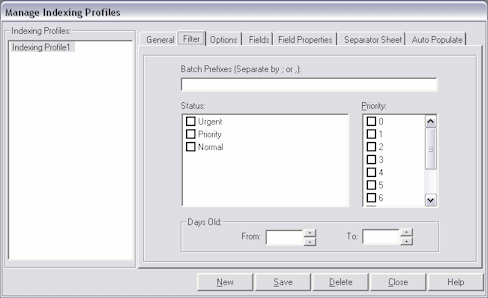
To display this screen, select Manage Index Profiles from the Indexing menu, then select the Filter tab.
| Element | Description |
|---|---|
| Batch Prefixes | Specify the prefix(es) for batches you want available for this profile. When the user selects this index profile, he or she will see batches with this prefix listed.
You can type up to eight characters per prefix. Separate multiple prefixes with a semi-colon or comma. Leave this field blank if you want all batches in the selected file cabinet available to users. |
| Status | Select the statuses of batches you want available for this profile. |
| Priority | Select the priorities of batches you want available for this profile. |
| Days Old (From/To) | Specify a range of days (i.e., days since batches were created) for batches you want available for this profile. |
Use this tab to select options that control how documents are indexed using the selected index profile.
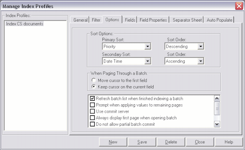
To display this screen, select Manage Index Profiles from the Indexing menu, then select the Options tab.
| Element | Description |
|---|---|
| Sort Options | Specify how batches are to be ordered when users select an index profile in the Batch Indexing screen. You can select a primary and secondary sort option, and select ascending or descending sorting for each option. In the profile shown above, Index will display batches for the selected profile first by priority (from highest to lowest), and secondly by their date and time (from least recent to most recent). |
| When Paging Through a Batch | Specify how you want the cursor to behave when users move to other pages in batches. You can set the cursor to either move to the first field or remain on the current field. |
| Refresh batch list when finished indexing a batch | When selected (the default), Index automatically updates the batch list display when the user returns to it after committing a batch. If deselected, users must click the Refresh button to update the batch list display. |
| Prompt when applying values to remaining pages | Select this field to prompt the user before applying index values to other pages in the document. When deselected (the default), values are automatically applied without asking the user. |
| Use Commit Server | Select this field to use Commit Server for commit processing. Commit Server performs scheduled batch commit processing on a separate server, instead of on indexing users' workstations. Select this option only if you have installed Commit Server. See "About Commit Server" for more information. |
| Always display first page when opening batch | Select this field to display a batch's first page to users upon opening it. If deselected (the default), Capture displays the first unindexed page of a batch when opened. |
| Do not allow partial batch commit | Select this field to prevent committing until all pages in the batch have been indexed. |
| Prevent thumbnail support | Select this field to prevent users from displaying thumbnails. When checked, the toolbar's View button is disabled to users in the Indexing screen. |
| Open next batch upon complete commit | When selected, Capture automatically opens and displays the next available batch for indexing after all of the current batch's documents have been successfully committed. If deselected (the default), Capture displays the Batch Indexing screen instead. |
| Disable date field calendar | Select this field to prevent the pop-up calendar from displaying to users in date-type index fields. When deselected, a calendar displays when a user clicks the down arrow at the right of a date field. You may want to disable the calendar to prevent conflicts with input masks. |
| Fit to Window upon navigating to a different page | Select this field to display pages in Fit to Window mode whenever the user moves between them, even if the user changed magnification using the Zoom In or Zoom Out buttons. When not checked (default), the last selected magnification is used when the user displays a different page. This option can be useful when batches contain pages of varying sizes. |
| Allow auto populated field(s) to index page | Autopopulated fields can affect whether pages are considered indexed and therefore whether a field is sticky. This field works in conjunction with the Sticky field options on the Field Properties tab, as described in "Manage Index Profiles, Field Properties Tab". |
Use this tab to specify the index fields users will complete when indexing with the selected profile.
|
Note: You can auto-populate any available field, regardless of whether you choose to display it to the user. (See "Manage Index Profiles, Auto Populate Tab".) |
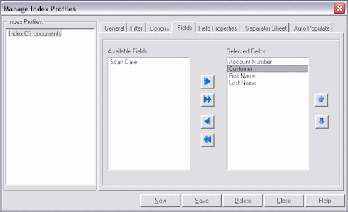
To display this screen, select Manage Index Profiles from the Indexing menu, then select the Fields tab.
| Element | Description |
|---|---|
| Available Fields | Lists index fields defined for the selected file cabinet and available for selection. |
| Selected Fields | Lists index fields selected for user entry for this profile. |
| Left, Right Arrows | Click these buttons to move selected index fields between the Available Fields and Selected Fields boxes.
|
| Up, Down Arrows | Click these buttons to reorder the fields in the Selected Fields field. This determines the order in which the fields are displayed while indexing. |
This tab's options affect how users index images. You select an index field from those defined on the Fields tab and apply options to it, then select another index field and apply options to it, and so on.
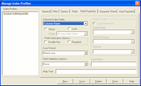
To display this screen, select Manage Index Profiles from the Indexing menu, then select the Field Properties tab.
| Element | Description |
|---|---|
| Selected Index Fields | Choose the index field you want to set properties for. This list includes all index fields selected on the Fields tab. |
| Sticky | Select this field to make the index field sticky.
An indexing user types a value in an indexing field, then moves to the next page. If the field is sticky (and blank), the value typed is automatically pasted into that indexing field on each subsequent page he or she displays. Use the When field options to specify when the indexing field should be sticky. For details, see "Sticky Index Fields". |
| Lock | Select this field to make the index field locked. Locking a field prevents the indexing user from entering or changing its value.
Note: This option is particularly useful when combined with a pick-list to ensure the user selects an existing pick-list item. |
| Field Verification Options | Use these options to help verify the user's data entry. You can choose:
|
| Case Format | Specify how text is formatted when the user presses Tab to move to the next index field. You can choose:
|
| Field Validation Options | Use these options to affect how users enter or select values. You can choose None, Input Mask (see Table 8-1 and Table 8-2), Pick-list (see "About Pick-lists",) Bar Code Field (see "Applying Bar Code Values to Index Fields") or Input Format (see Table 8-3 and Table 8-4). |
| Help Text | Use this field to include procedural tips or instructions for users. Text you type here for this field is displayed to users in the status bar when they move the cursor to the field. |
To set up a mask, choose Input Mask in the Field Validation Options field, then enter any of the available mask characters listed in Table 8-1 into the Input Mask field that displays. Any other characters you type are displayed exactly as typed.
Table 8-1 Input Mask Characters
| Mask Character | Description |
|---|---|
|
# |
Requires a number to be entered. |
|
. |
Decimal. The actual character used is whatever has been specified as the decimal placeholder in your Regional Settings (Windows Control Panel). This is treated as a literal. |
|
, |
Thousands separator. The actual character used is whatever has been specified as the thousands separator in your Regional Settings (Windows Control Panel). This is treated as a literal. |
|
: |
Time separator. The actual character used is whatever has been specified as the time separator in your Regional Settings (Windows Control Panel). This is treated as a literal. |
|
/ |
Date separator. The actual character used is whatever has been specified as the date separator in your Regional Settings (Windows Control Panel). This is treated as a literal. |
|
\ |
Treat the next character in the mask string as a literal. This allows you to use #, &, A, and ? as mask characters. This is treated as a literal. |
|
& |
Character placeholder. Valid values for this placeholder are ANSI characters 32-126 and 128-255. |
|
> |
Convert all following characters to uppercase. |
|
< |
Convert all following characters to lowercase. |
|
A |
Alphanumeric character placeholder where entry is required. |
|
a |
Alphanumeric character placeholder where entry is not required. |
|
9 |
Digit placeholder where entry is not required. |
|
C |
Character or space placeholder where entry is not required. This is the same as the & placeholder. |
|
? |
Letter placeholder. |
Table 8-1 lists examples of input masks.
Table 8-2 Input Mask Examples
| Input Mask | Description | Example Format |
|---|---|---|
|
###-##-#### |
Social Security Number |
123-45-6789 |
|
##-???-## |
Medium date |
17-July-09 |
|
##-##-## |
Short date |
07-17-09 |
|
##:## ?? |
Medium time |
03:15 PM |
To configure an input format, choose Input Format in the Field Validation Options field, then select or enter an input format into the Input Format field that displays. Table 8-3 lists available input formats.
Table 8-3 Input Formats
| Input Format | Description |
|---|---|
|
Custom |
Enter a custom format to be used. See Table 8-4. |
|
Currency |
Number with thousand separator, if appropriate, and two digits to the right of the decimal separator. Output is based on system locale settings. |
|
General Date |
A date and/or time. For real numbers, changes to a date and time; for example, 4/3/09 05:34 PM. If there is no fractional part, changes to only a date; for example, 4/3/09. If there is no integer part, changes to time only; for example, 05:34 PM. Date display is determined by the system locale settings. |
|
Short Date |
Date using the system's short date format. Date display is determined by the system locale settings. |
|
Medium Date |
Date using the medium date format appropriate for the language version of the host application. Date display is determined by the system locale settings. |
|
Long Date |
Date according to the system's long date format. |
|
Short Time |
Time using the 24-hour format; for example, 17:45. |
|
Medium Time |
Time in 12-hour format using hours and minutes and the AM/PM designator. |
|
Long Time |
Time using the system's long time format; includes hours, minutes, seconds. |
|
General Number |
Number with no thousand separator (for example, 7500). |
|
Fixed Number |
At least one digit to the left and two digits to the right of the decimal separator (for example, 7500.16). |
|
Standard Number |
Number with thousand separator, at least one digit to the left and two digits to the right of the decimal separator (for example, 7,500.16). |
|
Date formats |
Select from one of the following date formats: yyyy-mm-dd yyyy-mm-dd hh:mm yyyy-mm-dd hh:mm:ss yyyy-mm-dd hh:mm:ss AMPM mm-dd-yyyy mm-dd-yyyy hh:mm mm-dd-yyyy hh:mm:ss mm-dd-yyyy hh:mm:ss AMPM dd-mm-yyyy dd-mm-yyyy hh:mm dd-mm-yyyy hh:mm:ss dd-mm-yyyy hh:mm:ss AM mm/dd/yyyy mm/dd/yyyy hh:mm mm/dd/yyyy hh:mm:ss mm/dd/yyyy hh:mm:ss AMPM yyyy/mm/dd yyyy/mm/dd hh:mm yyyy/mm/dd hh:mm:ss yyyy/mm/dd hh:mm:ss AMPM |
In addition to predefined input forms, you can create custom character or numeric formats, as described in Table 8-4.
Table 8-4 Custom Input Formats
| Character | Description |
|---|---|
|
@ |
Character placeholder. Display a character or a space. If the string has a character in the position where the at symbol (@) appears in the format string, display it; otherwise, display a space in that position. Placeholders are filled from right to left unless there is an exclamation point character (!) in the format string. |
|
& |
Character placeholder. Display a character or nothing. If the string has a character in the position where the ampersand (&) appears, display it; otherwise, display nothing. Placeholders are filled from right to left unless there is an exclamation point character (!) in the format string. |
|
< |
Force lowercase. Display all characters in lowercase format. Example: A user entry of HELLO becomes hello |
|
> |
Force uppercase. Display all characters in uppercase format. Example: A user entry of This is it becomes THIS IS IT |
|
! |
Force left to right fill of placeholders. The default is to fill placeholders from right to left. |
|
(0) |
Digit placeholder. Display a digit or a zero. If the expression has a digit in the position where the 0 appears in the format string, display it; otherwise, display a zero in that position. If the number has fewer digits than there are zeros (on either side of the decimal) in the format expression, display leading or trailing zeros. If the number has more digits to the right of the decimal separator than there are zeros to the right of the decimal separator in the format expression, round the number to as many decimal places as there are zeros. If the number has more digits to the left of the decimal separator than there are zeros to the left of the decimal separator in the format expression, display the extra digits without modification. |
|
(#) |
Digit placeholder. Display a digit or nothing. If the expression has a digit in the position where the # appears in the format string, display it; otherwise, display nothing in that position. This symbol works like the 0 digit placeholder, except that leading and trailing zeros aren't displayed if the number has the same or fewer digits than there are # characters on either side of the decimal separator in the format expression. Example: With an input format of ##,##0.00, a user entry of 5459.4 becomes 5,459.40. |
|
(.) |
Decimal placeholder. In some locales, a comma is used as the decimal separator. The decimal placeholder determines how many digits are displayed to the left and right of the decimal separator. If the format expression contains only number signs to the left of this symbol, numbers smaller than 1 begin with a decimal separator. To display a leading zero displayed with fractional numbers, use 0 as the first digit placeholder to the left of the decimal separator. The actual character used as a decimal placeholder in the formatted output depends on the Number Format recognized by the system. |
|
(%) |
Percentage placeholder. The expression is multiplied by 100. The percent character (%) is inserted in the position where it appears in the format string. Example: With an input format of 0.00%, a user entry of 5 becomes 500.00% |
|
(,) |
Thousand separator. In some locales, a period is used as a thousand separator. The thousand separator separates thousands from hundreds within a number that has four or more places to the left of the decimal separator. Standard use of the thousand separator is specified if the format contains a thousand separator surrounded by digit placeholders (0 or #). Two adjacent thousand separators or a thousand separator immediately to the left of the decimal separator (whether or not a decimal is specified) means scale the number by dividing it by 1000, rounding as needed. For example, you can use the format string ##0,, to represent 100 million as 100. Numbers smaller than 1 million are displayed as 0. Two adjacent thousand separators in any position other than immediately to the left of the decimal separator are treated simply as specifying the use of a thousand separator. The actual character used as the thousand separator in the formatted output depends on the Number Format recognized by the system. |
|
(:) |
Time separator. In some locales, other characters may be used to represent the time separator. The time separator separates hours, minutes, and seconds when time values are formatted. The actual character used as the time separator in formatted output is determined by system settings. |
|
(/) |
Date separator. In some locales, other characters may be used to represent the date separator. The date separator separates the day, month, and year when date values are formatted. The actual character used as the date separator in formatted output is determined by system settings. |
|
(E- E+ e- e_) |
Scientific format. If the format expression contains at least one digit placeholder (0 or #) to the right of E-, E+, e-, or e+, the number is displayed in scientific format and E or e is inserted between the number and its exponent. The number of digit placeholders to the right determines the number of digits in the exponent. Use E- or e- to place a minus sign next to negative exponents. Use E+ or e+ to place a minus sign next to negative exponents and a plus sign next to positive exponents. |
|
(\) |
Examples of characters that can't be displayed as literal characters are the date-formatting and time-formatting characters (a, c, d, h, m, n, p, q, s, t, w, y, / and :), the numeric-formatting characters (#, 0, %, E, e, comma, and period), and the string-formatting characters (@, &, <, >, and !). Display the next character in the format string. To display a character that has special meaning as a literal character, precede it with a backslash (\). The backslash itself isn't displayed. Using a backslash is the same as enclosing the next character in double quotation marks. To display a backslash, use two backslashes (\\). |
|
- + $ () |
Display a literal character. To display a character other than one of those listed, precede it with a backslash (\) or enclose it in double quotation marks (" "). |
|
("ABC") |
Display the string inside the double quotation marks (" "). To include a string in format from within code, you must use Chr(34) to enclose the text (34 is the character code for a quotation mark (")). |
Use the Separator Sheet tab to set up separator sheet indexing.
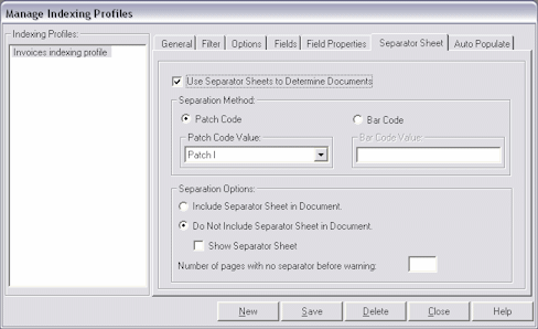
To display this screen, select Manage Index Profiles from the Indexing menu, then select the Separator Sheet tab.
| Element | Description |
|---|---|
| Use Separator Sheets to Determine Document | Select this field to enable the Separator Sheet options. |
| Separation Method | Select patch code or bar code options.
|
| Separation Options | Decide if you want to include the separator sheet in the document.
|
Use the Auto Populate tab to set up automatically indexed fields. You can configure Index to automatically fill (populate) selected index fields with certain values. For example, you might want to automatically populate a date field with the batch's scan date instead of having users type it in. Or, you might want to provide a default value for a field that the user could change if needed.
|
Note: Fields do not have to be selected for display on the Fields tab in order to be auto-populated. See "Manage Index Profiles, Fields Tab". |
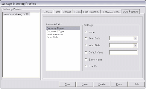
To display this screen, select Manage Index Profiles from the Indexing menu, then select the Auto Populate tab.
| Element | Description |
|---|---|
| Available Fields | Select the index field you want to auto-populate. The Available Fields field lists all fields in the file cabinet, not just those selected for display to the user. Index detects each field's data type, and displays available settings in the Settings area based on its type. |
| Settings | Select a system value. (The options available depend on the data type of the field you selected.) You can choose:
|
Use the Zone Editor to set up zones and OCR for index fields.
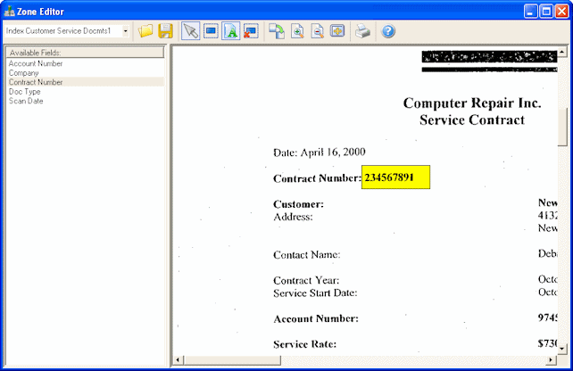
To display the Zone Editor, click the Zone Editor button on the toolbar of the Oracle Document Capture screen.
| Element | Description |
|---|---|
| Index Profile | Select the index profile to which to apply zones. |
| Available Fields | Select an index field from those set for user entry in the index profiles (see "Manage Index Profiles, Fields Tab"). You can set one zone for each index field. The selected field's zone is displayed in yellow and other zones are displayed in turquoise.) |
| Open Image File | Displays a standard file dialog box from which to open a TIFF, BMP, or JPG format image to use as a template for defining zones. |
| Save | Save the zones and image with the profile, allowing you to make changes to the zones later using the same image. |
| Pointer | Select a zone in order to move or resize it, delete it, or activate OCR for it. |
| Create Zone | Click this button to create a zone, then click and drag to define a zone on the image. |
| OCR Field | Click this button to turn on OCR for the selected zone. |
| Delete Zone | Click this button to delete the selected zone. |
| Rotate Right | Click this button to rotate the image. |
| Zoom In, Zoom Out, Fit to Window | Change the image page view by zooming in or out. |
| Click this button to print the image. |