11 Oracle VM Server for SPARC
Oracle Solaris VM Server for SPARC technology, formerly known as Logical Domains or LDoms, enables server virtualization on SPARC platforms. You can create and manage multiple virtual machine instances simultaneously on a single SPARC machine. Each virtual machine, or guest, can run a different operating system.
With Enterprise Manager Ops Center, you can monitor and manage all of the virtual machines from a single browser user interface. You can use virtual pool technology to maximize capacity without overloading a server. To balance the load, you can move a virtual machine from one physical system to another system either automatically or rmanually, from the user interface.
In this release you can perform the following tasks:
-
Provision the system to create Control Domain
-
Reboot, and shut down the Oracle VM Server
-
Monitor and interpret the performance of Oracle VM Server
-
Create and provision logical domains
-
Manage logical domains, including editing, migrating, starting, rebooting, and shutting down domains
-
Monitor and interpret the performance of logical domain
About Oracle VM Server for SPARC
You use hardware virtualization to create multiple virtual machines on a single piece of physical hardware. Unlike Oracle Solaris Zones, where the operating system is the same for each non-global zone, virtual machines can run on full instances of different operating systems, or different versions of the same operating system. These instances are called logical domains.
Oracle VM Server for SPARC technology, formerly known as Logical Domains or LDoms, is virtualization of SPARC servers. This technology is part of a suite of methodologies for consolidation and resource management for SPARC Chip Multi Threading (CMT) systems. This technology allows you to allocate a system's various resources, such as memory, CPU threads, and devices, into logical groupings and create multiple discrete systems. These discrete systems have their own operating system, resources, and identity within a single system. By careful architecture, an Oracle VM Server for SPARC environment can help you achieve greater resource usage, better scaling, and increased security and isolation.
When Oracle VM Server for SPARC software is installed, a domain called the control domain is created. From this control domain, you create virtual machines called logical domains that each run an independent OS. A logical domain is a virtual machine with resources, such as a boot environment, CPU threads, memory, I/O devices, and its own operating system. The control domain manages the logical domains. Each logical domain can be created, destroyed, reconfigured, and rebooted independently of other logical domains.
Oracle VM Server for SPARC functionality is especially useful in the following scenarios:
-
To combine several small UNIX and Linux servers, you can create logical domains to host the applications running on those servers.
-
To use different OS kernels in the same system, you can create logical domains to host different OS kernels.
-
To provide maximum isolation and security, logical domains provide separate OS and hardware resources.
-
To replace multiple legacy servers, set up a one-to-one mapping from legacy servers to the logical domains.
See Additional Resources for links to the Oracle VM Server for SPARC product documentation.
Enterprise Manager Ops Center and Oracle VM Server
Enterprise Manager Ops Center can manage logical domains that are created through the its user interface. When you use Enterprise Manager Ops Center to provision the Oracle VM Server for SPARC software, Enterprise Manager Ops Center installs the Oracle Solaris OS, the control domain, and an agent on the target system. This provisioning action removes existing virtualization software, including any logical domains.
Note:
You can discover logical domains that were created through the native CLI and display them in the Assets tree. However, you cannot use Enterprise Manager Ops Center to perform any actions on those domains.Requirements for Oracle VM Server for SPARC
Enterprise Manager Ops Center supports Oracle VM Server for SPARC 1.2, 1.3, 2.0, and 2.1 version. The Oracle VM Server must meet specific hardware, OS, and firmware requirements.
Note:
The OS in the control domain must have the default locale set to C. The control domain provisioning is supported on Oracle SPARC or x86 Proxy Controllers, but not on Linux Proxy Controllers.Note:
To provision the Oracle VM Server for SPARC software, the proper system model name must be populated on the service processor. The model name is not available on the service processor of the Sun Blade T6320 hardware.Architecture of Oracle VM Server for SPARC
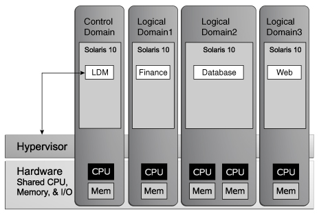
Figure 11-1 shows a sample architecture that contains a control domain and three logical domains. The system administrator created a logical domain for different areas of company. The first domain deploys a financial application; the second domain deploys a database application; the third domain deploys a web application. CPU threads and memory resources are assigned to each domains, depending on the requirements.
Figure 11-1 Sample Architecture for Oracle VM Server for SPARC
Description of "Figure 11-1 Sample Architecture for Oracle VM Server for SPARC"
The control domain handles the Oracle VM Server environment and creates the logical domains. The hypervisor is a firmware layer on the FLash PROM of the motherboard, operating between the OS and the hardware. The hypervisor provides a set of support functions to the OS, so that the OS does not need to call hardware functions.
Roles for Domains
Oracle VM Server for SPARC software's control domain, or virtual host, createw and manages the logical domains and allocates virtual resources to other domains. In addition to control domains and logical domains, the software can create domains for specific roles, such as a service domain and an IO domain.
An individual domain can have one or more of these roles, such as combining the functions of an I/O and service domain. In Enterprise Manager Ops Center, the control, service, and I/O domains are in the same domain.
-
Control Domain
The Oracle VM Server virtual host runs in the control domain. There can be only one control domain for each server. The first domain created after installing the Oracle VM Server software is the control domain and is named the primary domain. The control domain contains the SUNWldm packages, including the Oracle VM Server host application and the host daemon (ldmd) process required for managing logical domains. If you have an OS and other software running on a server and you install the Oracle VM Server software, that server becomes your control domain.
Note:
Zones are not supported in the control domain. You must not run user applications in the control domain and you cannot migrate, delete, or shut down a control domain. -
Logical Domain
The logical domain is a complete virtualized environment that has no ownership of physical I/O or virtual devices. This domain is managed by the control domain and uses services from the I/O and service domains. The logical domain must run an OS that supports both the sun4v platform and the virtual devices presented by the hypervisor.
-
Service Domain
The service domain provides virtual device services such as a virtual network switch, a virtual console concentrator, or a virtual disk service, to other domains.
-
I/O Domain
The I/O domain has direct access to physical I/O devices, such as a network card in a PCI Express controller. This domain shares the devices with others in the form of virtual devices when the I/O domain is also the control domain. The number of I/O domains that you can have depends on your platform architecture. For example, if you are using an UltraSPARC T1 processor, you can have a maximum of two I/O domains, with one of them being the control domain.
Configuration for an Oracle VM Server for SPARC
To install Oracle VM Server for SPARC software, apply a profile that specifies the values for resources such as CPU threads, crypto units, and memory as described in Creating an OS Profile for Oracle VM Server.
Note:
Enterprise Manager Ops Center does not support use of the LDoms configuration manager in LDoms 1.2. Do not attempt to reconfigure the control domain and logical domains using the native CLI of Logical Domain software.The recommended minimum configurations for the control domain are described in the following sections.
CPU Threads
The number of system CPUs determines the number of control domain CPU threads:
-
For less than 16 system CPUs, set the control domain CPU Threads to 2.
-
For between 16 and 64 system CPUs, set the control domain CPU Threads to 4.
-
For more than 64 system CPUs, set the control domain CPU Threads to 8.
Crypto Units
Crypto units are the resources on the supported platforms that provide high-performance, dedicated cryptographic engines. These can be used for tasks such as encrypting and decrypting network traffic between a Secure Socket Layer (SSL) web server and an application server.
Each CPU core has one crypto unit and four or eight CPU threads. Because the crypto unit is part of a core, the crypto unit is bound only to domains that contains at least one thread from the parent core. Crypto units cannot be split as CPU threads are. For example, you have assigned the crypto unit for the first CPU core to the control domain. If a new logical domain is assigned a thread from the first CPU core and the crypto unit for that core is already assigned, the control domain cannot assign that crypto unit to the new logical domain. Allocation of crypto units might not succeed, especially if a core is split between domains. An Oracle VM Server might allocate fewer crypto units or none at all.
You must assign at least one crypto unit to the control domain because the crypto unit enables domain migration.
Example 11-1 Example of Crypto Unit Assignments
In UltraSPARC T1 based servers, one core is four CPU threads. Therefore, assign one crypto unit and four CPU threads to the control domain. These values are set in the OS profile for Oracle VM Server for SPARC.
In UltraSPARC T2 and T2 Plus based servers, one core is eight CPU threads. Therefore, assign one crypto unit and eight CPU threads to the control domain.
RAM
The amount of RAM for the control domain depends on the size of the system RAM::
-
For system RAM less than 8 GB, set the control domain's RAM to 1 GB.
-
For system RAM between 8 GB to 16 GB, set the control domain's RAM to 2 GB.
-
For system RAM greater than 64 GB, set th econtrol domain's RAM to 8 GB.
Additional Configurations
The following configuration for the control domain is performed during installation of Oracle VM Server for SPARC and does not need to be included in the profile:
-
A virtual network switch for each subnet named subnet-address_prefix-length, for example, 10.17.7.0_24
-
A virtual disk server named primary-vds0
-
A virtual console concentrator is named primary-vcc0
Creating an OS Profile for Oracle VM Server
Create a profile to install the Oracle VM Server for SPARC software, the OS, and to set the parameters for the control domain. Use this profile in a deployment plan that provisions a SPARC server's service processor.
Note:
The version of Oracle VM Server for SPARC to be installed depends on the target systems. After the provisioning job starts, an information problem displays the version that is installed on the target server.See Hardware And Provisioning Profiles and Deployment Plans for more information about creating profiles and plans, and applying the plans.
To Create an OS Profile for Oracle VM Server
-
Select Plan Management from the Navigation pane.
-
Select OS Provisioning in the Profiles and Policies tree. The OS Provisioning page is displayed in the center pane.
-
Select Create Profile in the Actions pane. The Create Profile-OS Provisioning wizard starts.
-
To identify the new profile, enter a name and a description for the profile.
-
To create a deployment plan that containsthe new profile, select the Create a deployment plan for this profile option .
-
For subtype, select Oracle VM Server. Click Next.
-
From the OS Image list, select the OS image that you want to install.
-
Select a Distribution Type. The minimum requirement is End User distribution. Distributions that are lower than End User require additional package dependencies and the provisioning job can fail if the packages are not present.
-
(Optional) To add a script to the profile, select Include Custom Scripts and then click the Add icon. Enter the location of the script, which must be accessible from the Enterprise Controller. Specify if you want to execute the script before or after the provisioning operation.
-
Specify the following parameters and then click Next:
-
Language – Select a Language from the list.
-
TimeZone – Specify the time zone for the OS.
-
Terminal Type– Select a terminal type from the list.
-
Console Serial Port – To monitor the installation using a serial connection, select the console serial port device.
-
Console Baud Rate– To monitor the installation using a serial connection, select the baud rate.
-
NFS4 Domain – Enter the NFS4 domain name that the target system will use. A dynamic NFSv4 domain name enables the name to be derived at run time, based on the naming service configuration. If you prefer, enter a static domain name.
-
Password –Enter the root password for the root user on systems provisioned using this profile. Re-enter the password for confirmation.
-
-
Select the Manual Net Boot option to enable manual control of network boot operations for the target system. You must select this option for a target system that does not have a service processor because Enterprise Manager Ops Center cannot control the network boot process remotely on these systems.
-
Select Automatically Manage with Oracle Enterprise Manager Ops Center to install an agent on the system. Click Next.
-
JET modules can be used to provision an OS. The base_config, custom, and flash JET modules are always installed. To specify additional JET modules that you have installed on the Proxy Controller to perform OS provisioning operations, enter a comma-separated list of the JET modules.
-
Click the Add icon to add JET name-value pairs. The JET parameters customize how this profile provisions the target systems.
-
Enter the name of the JET parameter that you want to add in the Name field.
-
Enter the value that you want to assign to the JET parameter in the Value field.
When you are finished, click Next.
-
-
Specify the resources that you want to assign to the control domain. The remaining resources are available for the logical domains.
Figure 11-2 Parameters for a Control Domain
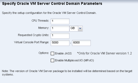
Description of "Figure 11-2 Parameters for a Control Domain"
-
CPU Threads – Specify the number of CPU threads that you want to assign to the control domain.
-
Memory – Specify the amount of memory that you want to assign to the control domain.
-
Requested Crypto Units – Specify the number of crypto units that you want to assign to the control domain.
-
Virtual Console Port Range – Specify the minimum port and maximum port of the virtual console of the control domain. The default port range for virtual console is 5000 to 6000.
-
Enable JASS – Select this check box to harden the system by installing the SUNWjass package.
Note:
JASS is not supported for Oracle VM Server for SPARC 1.3 or higher versions. This option is disregarded. -
Enable Multiplexed I/O (MPxIO) – Select this check box to enable Fibre Channel connectivity for the control domain. This action enables the Fibre Channel ports on the system that is configured for storage.
Click Next.
-
-
Specify the disk partitions and file systems that you want to create on the target system. The root (/) and a swap file system are defined by default. Click the Add icon to define a new partition. For each partition that you define, provide the following information:
-
File System Type – Select a file system type, either ufs, unnamed, or swap.
-
Mount Point – Enter a directory to use as a mount point for partitions.
-
Device – Enter the rootdisk keyword and a slice value to describe a partition on the target system's boot disk, for example, rootdisk.s0, or enter the logical device name, for example, c1t0d0s0, of the partition that you want to create.
-
Size (MB) – Enter the size that you want to assign to the partition, expressed in MB. Do not enter any value for the size when you want to allocate the remaining unused disk space to a file system.
Click Next,
-
-
Specify the name service, domain name and the corresponding name server. You can select the following name service:
-
DNS – Enter the domain name of the DNS server and enter the IP address of the DNS server in the Name Server field. You can enter up to three IP addresses as the value for the Name Server. Provide the additional domains to search for name service information in the Domain Name Search List. You can specify up to six domain names to search. The maximum length of each search entry is 250 characters.
-
NIS or NIS+ – Enter the domain name of the NIS or NIS+ server. If you know the NIS server details, choose the option Specify an NIS Server and enter the NIS server host name and the IP address.
-
LDAP – Enter the domain name of the LDAP server. Specify the name of the LDAP Profile you want to use to configure the system. Enter the IP address of the LDAP Profile Server. You can also provide the Proxy Bind Distinguished Name and Password.
-
None – Select None when there is no naming service configured.
Click Next.
-
-
Select one of the network interface options for the target system:
-
Select a DHCP-enabled network interface for the boot interface from the list of all managed networks. Click the Add icon to add more networks.
-
For each network, select a NIC from the list of available interfaces.
-
Select the Address Allocation Method for the network except the boot interface. If you select Use Static IP, you must provide the IP address when you apply the profile so that the IP address can be assigned to the target system after provisioning.
-
-
To specify and configure the Link Aggregation, enter the following:
-
Link Aggregation Name – The name of the Link Aggregation is set to "
aggr". Add an integer to differentiate this aggegation from other aggregations. -
Network – Select a network from the list.
-
NICs – List the physical interfaces of the selected network that must be configured as a single unit.
Click Next to configure the link aggregation.
-
-
Configure the IEEE 802.3ad Link Aggregation with the following parameters:
-
Load Balancing Policy – Define the policy for outgoing traffic.
-
Aggregation Mode and Switches –- If the aggregation topology connects through a switch, determine whether the switch supports the Link Aggregation Control Protocol (LACP). If the switch supports LACP, you must configure LACP for the switch and the aggregation. Define one of the modes in which LACP must operate.
-
MAC Address Policy – Define whether the MAC address of the NICs are fixed.
-
-
In the Specify IPMP Group step, define the following information:
-
IPMP Group Name – Provide a name for the IPMP group.
-
Network – Select a network from the list.
-
Failure Detection – The Link-based detection is always embedded. If you want to include Probe-based detection, select the Probe option.to specify the IPMP interfaces. Test address is not required for probe-based failure detection.
Click Next.
-
-
To specify an IPMP interfaces, define the following information. The data and test addresses are assigned when the profile is applied.
-
Specify the interfaces that will be part of the IPMP group.
-
Define the interfaces as Failover or Standby.
-
Configure additional IP addresses for the interfaces.
Click Next.
-
-
Review the Summary of your selections. Click Finish to crete the profile.
See Deployment Plans and Plans for creating a plan with this profile and apply the plan to provision the Oracle VM Server.
Provisioning Oracle VM Server for SPARC
You can install the software on bare-metal or on systems that is already configured with logical domains. When you provision Oracle VM Server through Enterprise Manager Ops Center, any previous configuration is removed from the service processor by resetting the service processor to its factory defaults.
When you provision Oracle VM Server for SPARC, the instance of the Oracle Solaris OS becomes the Control Domain which is the first domain to be created. The virtual host on which this instance of Oracle Solaris OS runs is called the Oracle VM Server Host or simply, Oracle VM Server. The Logical Domains Manager runs in the control domain to create and manage logical domains. You can have only one control domain per server. You cannot change the name or destroy the control domain.
This section describes how to install the Oracle VM Server for SPARC software on a service processor.
The Oracle VM Server for SPARC provisioning job performs the following major tasks:
-
Downloads the appropriate OS image.
-
Initiates a net boot action on the Service Processor.
-
Configures DHCP and installs the OS.
-
Installs the Oracle VM Server Host.
-
Configures Oracle VM Server Host according to the values set in the profile such as memory, CPU threads, Crypto units, and virtual console port range.
-
Depending on the version, installs the SUNWJass package to harden the system.
-
Enables the Fibre Channel ports on the system that is configured for storage.
-
Installs and configures the agent. Do not install the agent manually on the Oracle VM Server host.
Before You Begin
-
The Oracle VM Server for SPARC software depends on particular Oracle Solaris OS versions, required software patches, and particular versions of system firmware. See Requirements for Oracle VM Server for SPARC .
-
Discover the target system on which you want to install Oracle VM Server for SPARC software.
-
Configure DHCP services on Proxy Controllers. See CONFIGURING DHCP.
-
Create a profile for provisioning Oracle VM Server for SPARC. See Creating an OS Profile for Oracle VM Server.
-
Create a deployment plan with the profile created for provisioning Oracle VM Server for SPARC.
See Deployment Plans for information about creating a plan with this profile .
-
(Optional) Adjust the amount of time allowed for the job. The default time is three hours.
-
In the Enterprise Controller, edit the
/var/opt/sun/xvm/satellite.propertiesfile and locate the osp.default_timeout property.OS Provisioning ################################## # Default Timeout of OSP Job osp.default_timeout=180
-
Change the value of the property to the desired number of minutes.
-
Save and close the file. You must restart the Enterprise Controller after changing the value.
-
-
The Oracle VM Server for SPARC version to be provisioned is selected depending on the type of target server and firmware version. You can define the version to be provisioned explicitly. The version value is read during the provisioning job.
-
In the Enterprise Controller, edit the
/var/opt/sun/xvm/satellite.properties file. -
Add the following entry with one of the valid versions: 1.2, 1.3, 2.0, and 2.1.
osp.ldom_version=<version>
-
Save and close the file. You do not need to restart the Enterprise Controller.
To allow Enterprise Controller to determine the proper version of Oracle VM Server, edit the properties file and remove this entry.
-
To Apply the Profile on the Target
You apply a profile to a target system by applying a deployment plan that contains the profile. The plan can contain other profiles too. You can apply the Oracle VM Server provisioning profile in one of the following ways:
Method 1: Select the Target
-
Select the server that will become the Oracle VM Server host from the Assets sections.
-
Click Install Server option from Deploy in the Actions pane. The Install Server window is displayed. The list of available plans for provisioning OS is also displayed.
-
Select a plan from the list or, to create a new plan, click Create New Plan and use the following procedure.
-
Click Apply Plan. The job to provision Oracle VM Server for SPARC starts.
To create a new deployment plan:
-
Click Create New Plan. The Select Plan Type window is displayed.
-
Select one plan type, either Provision OS or Install Server.
-
Click Create New Plan. The Create Deployment Plan window is displayed.
Method 2: Select the Plan
-
Select the deployment plan from the Plan Management section in the Navigation pane.
-
Select Apply Deployment Plan from the Actions pane. The Select Assets window is displayed.
-
Select a server from the list of available targets and click Add to Target List. You can add more than one target to apply the plan.
-
Select whether you want to apply the plan with minimal user interaction or override any profile values. In either case, the Provision OS wizard starts. If you chose to override profile values, select options and edit the parameters for each step in the wizard. If you chose minimal user interaction option, you specify the resources.
-
Specify the network resources for each target.
-
Enter the IP address for each target.
-
Review the summary of the parameters for provisioning the Oracle VM Server.
-
Click Apply the deployment plan on the selected targets.
Initiating Manual Net Boot
A target system requires a manual net boot operation if Enterprise Manager Ops Center cannot perform a remote network boot process. Profiles that provision this type of system contain the Manual Net Boot option. You must initiate the net boot operation when the Oracle VM Server provisioning job is completed.
-
Log in to the service processor of the target system.
-
If the target system is running, enter
halt. -
Enter the following command
boot net:dhcp - install
Provisioning the Oracle VM Server Version
The version of Oracle VM Server for SPARC software installed on the target server is determined during the execution of the job, unless you have defined the version explicitly. The version installed depends on the following conditions:
-
If the target is a T1 server, the Oracle VM Server for SPARC 1.2 version is installed. The Oracle VM Server SPARC versions 1.3 and 2.0 are not supported for T1 servers.
-
The system-firmware versions also determines the version of Oracle VM Server for SPARC that is installed.
-
For Firmware 7.1.x , Oracle VM Server for SPARC 1.2 is installed.
-
For Firmware 7.2.0 to 7.2.6 , Oracle VM Server for SPARC 1.3 is installed.
-
For Firmware 8.0Firmware 7.4.0 on UltraSPARC T2 and UltraSPARC T2 Plus Servers – Oracle VM Server for SPARC 2.1.0 or higher , Oracle VM Server for SPARC 2.0 is installed.
-
Firmware 8.1.0 on SPARC T3 Servers – Oracle VM Server for SPARC 2.1.
-
-
The JASS that is used for hardening the system does not apply to Oracle VM Server for SPARC 1.3 and 2.0 versions. If you have selected the Enable JASS option, the option is skipped when installing Oracle VM Server for SPARC 1.3, 2.0, and 2.1 versions. A notification is sent if this even occurs.
Managing Oracle VM Server
To manage the resources for Oracle VM Server, you edit the resource configuration such as CPU Threads, Crypto Units, and memory. You can associate storage libraries with the Oracle VM Server and monitor the performance of logical domains..
Viewing Information About an Oracle VM Server
When you select an Oracle VM Server from the Assets tree, Enterprise Manager Ops Center displays information about it in the center pane. From the center pane, you can select tabs and actions to manage the Oracle VM Server.
To View Information About an Oracle VM Server
-
Select an Oracle VM Server from the Assets section in the Navigation pane.
-
Click on one of the tabs in the center pane to view details of the Oracle VM Server's configuration.
-
Dashboard
-
Summary – The summary of the group to which the Oracle VM Server belongs.
-
Membership Graphs – A graphical representation of the group members and its relationships.
-
Status – A graphical representation of unassigned problems and a table of recent problems.
-
-
Summary
-
Name
-
Description
-
Status
-
CPU Info
-
Available CPU Threads
-
Available Crypto Units
-
Available memory
-
Version of Logical Domains Manager
-
Control Domain specification
-
Resource utilization of Oracle VM Server
-
Logical domains, and their status and specification
-
Virtual pool
-
Reachability
-
-
Libraries
The Libraries tab displays thestorage libraries that are associated with the Oracle VM Server. When you select a library, the logical domains that are associated with this library are listed under Usage section. You can also view the contents of the library from the Contents section.
The icons perform the following actions::
-
Associate Libraries – Add an existing storge library to the Oracle VM Server. See Associating Libraries With Oracle VM Server
-
New Local Library – Create a storage library on the Enterprise Controller.
-
Edit Local Library – Change the attributes of an existing local library.
-
Delete Local Library – Remove the local library.
-
Disassociate Library – Remove the connection between the library and the Oracle VM Server.
-
-
Networks
The Networks tab lists the networks that are connected to the Oracle VM Server. You can attach the Oracle VM Server to more than one network. When you select a network from the list, the connectivity information and the logical domains using the network are displayed.
The icons perform the following actions::
-
Attach Network – Connect the Oracle VM Server to the selected network.
-
Unbind Network from Virtual Pool – Disconnect the selected network from Oracle VM Server.
-
Modify Physical Connectivity – Edit the connectivity attributes of the selected network.
-
Refresh DHCP Connectivity – Re-connect to the DHCP server.
See Managing Networks of Oracle VM Server for detailed procedures.
Note:
You cannot modify or delete the management network of the Oracle VM Server. -
-
Problems
The Problems tab lists the problems that are reported for the Oracle VM Server. It provides the list of unresolved problems and a graphical representation of the problem composition.
To see the corresponding alerts for each problem, see Problem Management for more detailed information.
-
Monitoring
The Monitoring tab shows the monitoring values and boundaries that are set for Oracle VM Server activity. You can review the rules, monitoring attributes, specific time period for monitoring, and the level of severity for monitoring the activity of Oracle VM Server. To change these values, see Monitoring Profiles.
-
The Charts tab displays the CPU, memory and network utilization of the Oracle VM Server. The data is collected in five-minute intervals and is displayed graphically. The utilization data is provided for different time intervals. See About Charts for more information about reading charts.
-
Jobs
The Jobs tab lists the current and completed jobs of the Oracle VM Server. See Job Management for more information about managing jobs.)
-
Configuration
The Configuration tab displays information such as remote logging, routing, NFS domain name, and name service information for the Oracle VM Server.
Editing the Attributes of Oracle VM Server
You can modify the attributes of Oracle VM Server such as name, description, tags, CPU Threads or Crypto Units (MAUs), and memory size.
The Oracle VM Server must have Oracle Solaris 10 10/09 or later provisioned to edit the attributes.
To Edit the Attributes of an Oracle VM Server
-
Click Assets and then select the Oracle VM Server in the Navigation pane.
-
Select the Summary tab in the center pane.
-
Select Edit Attributes from the Actions pane.
-
Change the values for any of the followingattributes.
-
Name and Descriptiong
-
Tags
-
CPU Threads
-
Memory size
-
Crypto Units
-
-
Click the Save icon to save the changes.
When you modify the memory size, Oracle VM Server is rebooted unless it is running Oracle VM Server for SPARC 2.0 version.
Rebooting an Oracle VM Server Host
An Oracle VM Server can be rebooted regardless of the state of the logical domains. During the reboot, the logical domains might suspend temporarily but keep their current states.
To Reboot an Oracle VM Server Host
-
Select an Oracle VM Server from the Assets section in the Navigation pane.
-
Click Reboot Oracle VM Server Host in the Actions pane.
-
To confirm the action, click Reboot Oracle VM Server in the window. A job is submitted to reboot the Oracle VM Server. . If you were logged into the server console, you must log in again.
Associating Libraries With Oracle VM Server
Oracle VM Server uses storage libraries and software librarie to create logical domains and to maintain their data.
To Associate Libraries With Oracle VM Server
-
Select an Oracle VM Server from the Assets section in the Navigation pane.
-
Select Associates Libraries in the Actions pane. As an alternative, you can select the Libraries tab in the center pane and then click the Associate Libraries icon. The Associate Libraries window is displayed.
-
In the Available Libraries table, select the libraries that you want to associate with the Oracle VM Server.
-
Click Associate Libraries. A job is submitted to associate the selected libraries with the Oracle VM Server.
Managing Networks of Oracle VM Server
You can assign networks to Oracle VM Server and also unbind the networks. You can now assign a network multiple times to an Oracle VM Server to connect the logical domains to a network multiple times. Oracle VM Server creates a virtual switch for each network connections. Each switch is numbered and then incremented for each connection created.
See About IPMP Groups and Aggregated Links for detailed information.
Enterprise Manager Ops Center provides the option to attach networks to stand-alone Oracle VM Servers. When you select a stand-alone Oracle VM Server in the Assets tree, the Attach Network option is available in the Actions pane. This option is not available for Oracle VM Servers that belong to a virtual pool. See Managing Networks of a Virtual Pool for assigning networks to virtual pool.
To Attach Networks to Stand-Alone Oracle VM Servers
-
Select the Oracle VM Server from the Assets tree in the Navigation pane.
-
Select Attach Networks in the Actions pane.
-
Select a network to assign to the Oracle VM Server.
-
Enter the number of connections to the network. To assign more networks, click the Add icon. Click Next.
-
For each connection, define the interface:
-
Select the NICs from the list for each connection.
-
-
Specify the Address Allocation for each network connection:
-
For Static IP, specify the IP address.
-
For Assign By DHCP, specifiy the IP address of the DHCP server used by the Oracle VM Server.
Click Next.
-
-
Review the attributes and then click Finish to assign the network to Oracle VM Server.
Creating Logical Domains
A logical domain is a virtual machine that has its own operating system and identity within a single server. Each logical domain can be created, destroyed, reconfigured, and rebooted independently, without requiring the server to be powered off. You can run a variety of applications in different logical domains to keep them independent for performance and security purposes.
Enterprise Manager Ops Center can create logical domains and install Oracle Solaris OS on them. Using profiles and deployment plans, you can to create more than one domain simultaneously and then save the configuration for future logical domains.
To create logical domains:
-
Create Logical Domain Profile and Plan – You create a profile which defines the configuration of the logical domain. Using the profile, you create a deployment plan. You apply the plan on an Oracle VM Server to create logical domains. The logical domains do not have the Oracle Solaris OS. You then select each logical domain and apply an OS provisioning plan to install the OS. See Provisioning Logical Domains for provisioning OS on the logical domains.
-
Configure and Install Logical Domains – This is a complex plan which contains deployment plans that create logical domains and install Oracle Solaris OS on them. You must have the required profiles and deployment plans available to create the complex plan..
Creating Logical Domain Profiles
A logical domain profile contains the requirements and configuration for an entire logical domain, including the CPU Threads, memory, storage, and network details . When a deployment plan applies the profile, you create a logical domain. You must provision Oracle Solaris OS on each domain separately. As an alternative, you can include the logical domain profile along with an OS provisioning profile in a complex plan.
See Logical Domain Profiles for detailed procedures for creating logical domain profiles and plans.
Provisioning Logical Domains
After you create a logical domain, you must provision an OS.
-
Ensure that you have imported the appropriate Solaris 10 (at least Solaris 10 8/07) ISO image into the library.
-
Create or identify an OS provisioning profile for SPARC. See Creating an OS Profile for Oracle VM Server.
-
Create or identify a deployment plan with the OS provisioning profile.
-
Select a logical domain from the Assets in the Navigation pane.
-
Select Install Server in the Actions pane. The Install Server window is displayed with the list of deployment plans for logical domains. If no plans are listed, click Create New Plan to create an OS provisioning plan. See Creating an OS Profile for Oracle VM Serverto create a plan.
-
Select an available plan from the list.
-
Select whether you want to apply the plan with minimal user interaction or override any profile values.
-
Click Apply Plan. The Provision OS wizard launches. You can apply the plan in the following methods:
-
Minimal user interaction – All the OS provisioning configuration values are applied but you are prompted to enter the network resource assignment such as the IP address of the system. Enter the IP address and click Next.
-
Override profile values – You apply each configuration value in the profile. Accept or change the values and then click Next.
-
-
Review the information in the Summary step and click Apply to install the OS on the logical domain.
Managing Logical Domains
To manage the logical domains that are created through Enterprise Manager Ops Center, you can do the following operations:
-
View and edit logical domain information.
-
Start a logical domain
-
Shut down a logical domain
-
Reboot a logical domain
-
Modify the attributes of a logical domain
-
Migrate logical domains
-
Add storage to logical domains
-
Connect networks to logical domains
Viewing Logical Domain Information
You can manage and monitor the logical domain using the tabbed windows in the center pane.
To View Logical Domain Information
-
Select a logical domain from the Assets pane. The Dashboard is displayed in the center pane with the following information:
-
Domain Name
Description
Status
Running Time
Operating System
Tag
Metadata Library
Boot Device
Membership Graph
Problem Status
-
-
Select one of the tabs.
-
Summary tab
-
Name, details and status
-
CPU Threads and utilization
-
Crypto units
-
Memory size
-
Boot device
-
Virtual disk images
-
Hourly chart of CPU and Memory Utilization
-
-
Console tab
Use the Console tab to connect to the virtual console of the logical domain. Click Enable Console to activate the console. See Using the Logical Domain Console.
-
Network tab
The Network tab displays the networks that are assigned to this logical domain with their details such as NIC Name, IP Address, MAC Address, and Network. See Managing Logical Domain Networks.
-
Storage tab
The total storage size of all the virtual disks that are associated with the this logical domain and a table showing each virtual disk is displayed. These virtual disks can be from NFS or local libraries, or LUNs from the Fibre Channel library. When you select a LUN , details such as name, vendor, GUID, product, status, and revision are displayed.You can add virtual disks and delete any of the virtual disks.
-
Problems tab
The Problems tab shows reported problems and lists unresolved critical problems. You can take the suggested actions and review the history of the alert. See Problem Management.
-
Monitoring tab
You can set monitoring rules to monitor the performance of the logical domain. You can view the set monitoring rules and the status of the rules set.
To change the monitoring values, see Monitoring Profiles.
-
Chart tab
The Charts tab displays the CPU and network utilization of the logical domain. The data is collected in five-minute intervals and is displayed graphically. The utilization data is provided for different time intervals. See About Charts for more information about reading charts.
-
Jobs tab
The Jobs tab lists the current and completed jobs of the logical domain. See Job Management for more information about managing jobs.
-
Editing the Attributes of a Logical Domain
You can change the attributes and resource assignments of a logical domain.
To Edit the Attributes of a Logical Domain
-
Select the logical domain in the Assets section of the Navigation pane. The Dashboard of the logical domain is displayed.
-
Select the Summary tab in the center pane.
-
In the Actions pane, click Edit Attributes.
-
Modify the values of Description, Tag, CPU threads, Crypto units, and Memory as required.
-
Click the Save icon to save the changes.
Starting a Logical Domain
To start a logical domain, you must select a stand-alone Oracle VM Server or virtual pool that has sufficient resources to host the logical domain. When you start a logical domain, the logical domain is powered on and the OS is booted.You can change the following during the start process:
-
Virtual pool wher e the Oracle VM Server resides
-
Oracle VM Server host of the logical domain
-
Network used by the logical domain
-
Select the logical domain that you want to start from the Assets section of the Navigation pane.
-
Select Start Guest from the Actions pane. The Start Guest wizard is displayed.
-
Select the virtual pool in which you want the logical domain to run. Click Next.
Note:
If any network is assigned to the logical domain but not associated with the virtual pool, the network is not available after the logical domain starts. -
Select the Oracle VM Server that is the host for the logical domain or choose a different Oracle VM Server. You can view the load of each Oracle VM Servers and select an Oracle VM Server from the table. Click Next.
-
Specify the network interfaces for the logical domain. Specify the virtual switch that connects to the logical domain's MAC address. You cannot connect the same virtual switch to two different MAC addresses
(Optional) You can select Do Not Connect if you do not want a connect a logical domain MAC address to any virtual switch.
Click Next .
-
Choose whether to start the logical domain immediately or to specify the date and time to start. Click Next.
-
Review the selected parameters and click Start to start the logical domain. A job is submitted to start the logical domain.
Managing Logical Domain Networks
You can connect to a logical domain to a network multiple times on the same Oracle VM Server. For each connection, a virtual switch is created in the Oracle VM Server but you must specify the NIC each virtual switch uses. This association is done when attaching networks to Oracle VM Server.
You can now create IPMP groups in logical domains manually. It takes approximately 15 minutes for a new IPMP group to display in the UI.
You can also aggregate the NICs for the logical domain and create an aggegated link.
See About IPMP Groups and Aggregated Links for information about IPMP and link aggregation support in Enterprise Manager Ops Center. For more information about creating IPMP and link aggregations, see Additional Resources.
To Connect a Logical Domain to a Network
-
Select a logical domain that is in shutdown state in the Assets section of the Navigation pane.
-
Click Connect Guest to Network in the Action pane. The Connect Guests to Network window is displayed. The networks that are not currently connected to the selected logical domain are displayed in the table.
-
Select a network that you want to connect to the logical domain. Use Shift and Ctrl keys to select more than one network.
-
Click Connect to Network. The selected network is connected to the logical domain
To Disconnect a Logical Domain from a Network
-
Select a logical domain that is in shutdown state in the Assets section of the Navigation pane.
-
Select the Network tab in the center pane. The list of connected networks are listed.
-
Select the network that you want to unbind.
-
Click the Disconnect Selected Guest From Network icon. The Unbind a Network window is displayed.
-
Select the network from the list.
-
Click Disconnect From Network to unbind the network from the logical domain. The selected network is disconnected from the logical domain.
Migrating a Logical Domain
You can migrate a logical domain from an Oracle VM Server to another virtual host within the same virtual pool. This type of migration is called warm migration. The logical domain is shut down or suspended and then its static configuration is moved to the target host. The logical domain is then restarted on the target host using the same virtual image. Warm migration does not maintain the live run state of the operating system, that is, going through a save-to-disk cycle during the migration. Shared storage is required for this implementation.
-
Verify that the source and target hosts are in the same virtual pool.
-
Verify that the source and target hosts are in the same network.
-
Verify that the source and target host have access to the storage library, that is, the disk image or guest metadata, for the logical domain .
-
For Oracle VM Server for SPARC 1.2 version, you can migrate with only 1 MAU.
For Oracle VM Server for SPARC 1.3 and 2.0 versions, you can migrate with any number of MAUs.
-
Verify that the target host has sufficient resources (CPU threads, memory) ato support the logical domain.
Note:
For Oracle VM Server for SPARC 2.1, you cannot migrate a logical domain to a previous version of the server such as 2.0, 1.3 or 1.2. You can migrate only within the same version of Oracle VM Server for SPARC.-
Select the logical domain from the Assets section of the Navigation pane.
-
Click Migrate Guest in the Actions pane.. The Migrate Logical Domain wizard is displayed.
-
Select the target Oracle VM Server, the new host of the logical domain. The eligible target Oracle VM Servers is displayed in order of decreasing preference. Click Next.
-
Review the migration Summary and click Finish to migrate the logical domain.
Rebooting a Logical Domain
You can reboot a logical domain from the Enterprise Manager Ops Center UI.
-
Select the logical domainfromt he Assets section of the Navigation pane..
-
Click Reboot Guest in the Actions panet. The Reboot Logical Domain window is displayed
-
Click Reboot Logical Domain to confirm. A job is submitted to reboot the logical domain.
Managing Storage of a Logical Domain
You can use the options Add Storage to Logical Domain and Remove Storage From selected Logical Domain to manage storage of logical domains.
Ensure that the logical domain is in the shut down state to enable the storage options on the UI.
To Add Storage to Logical Domain
-
Select the logical domain from the Assets section of the Navigation pane.
-
Select Add Storage to Logical Domain from the Actions pane. The Add Storage window is displayed.
-
Click the Add icon to add a storage to the logical domain.
-
Select an associated library from the list. The library can be local, NAS, SAN or local device library.
-
If the selected library is local or NAS, specify the size of the disk storage. You cannot specify the disk size for SAN and local device library.
-
(Optional) You can add storage from more than one associated library. The total additional storage disk will be displayed for Additional Storage Specified. The total value for logical domain storage is updated.
-
Click Finish. The selected storage will be added to the logical domain.
To Remove Storage from Logical Domain
-
Select the logical domain from the Assets section of the Navigation pane.
-
Select the Storage tab in the center pane. The list of storage is displayed.
-
Select the storage that you want to remove. The Remove Storage From Selected Logical Domain icon is enabled.
-
Click the Remove Storage From Logical Domain icon.
-
Click Delete to confirm the action. The selected storage will be removed from the logical domain.
Shutting Down a Logical Domain
When you shut down a logical domain, it is disconnected from its networks, disassociated from the Oracle VM Server control domain, and all the associated resources are released. You can restart the logical domain with the same configuration that is maintained in its storage library or you can restart the logical domain on a different Oracle VM Server.
-
Select a logical domain from the Assets section of the Navigation pane.
-
Click Shutdown Guest in the Actions pane.
-
Click Shutdown Logical Domain. A job is submitted to shut down the logical domain.
Deleting a Logical Domain
When you delete a logical domain, it is disconnected from the associated networks and is disassociated from the Oracle VM Server. All the associated resources are released and the domain configuration is removed from the library. All the references to the logical domain, including its disk image and snapshots are removed from the system. However, the logical domain profile and the plan that used the profile remains.
-
Select the logical domain from the Assets section of the Navigation pane..
-
Click Delete Guest in the Action pane.. The Delete Logical Domain window is displayed.
-
Click Delete Logical Domain. A job is submitted to delete the logical domain.
Using the Logical Domain Console
You can attach to the logical domain console from witin the Enterprise Manager Ops Center UI. You enable the console connection and then you connect to the console.
To Open a Logical Domain Console
-
Select the logical domain from the Assets section in the Navigation pane.
-
Select the Console tab in the center pane.
-
Click the Enable the Console Connection icon. A job is initiated to enable the console connection.
-
Click the Connect to the Console icon. The connection is established and the console appears on the UI.
-
Enter the user name and password to log into the logical domain.
-
(Optional) Click the Undock the Console icon to move the console window separately from the browser window.
-
(Optional) The default connection time is set to 120 minutes. To change the expiration time, click the Set Console Connection Timeout icon and enter a new time limit in minutes. The console connection is enabled for the new time limit. After the time limit, you must enable the console connection again.
Note:
If the logical domain is not in view in the Assets tree, the console is logged out automatically but the connection exists until the connection time expires. You must log in again.To Close a Logical Domain Console
-
Select the logical domain from the Assets tree in the Navigation pane.
-
Select the Console tab in the center pane. The logical domain console that is already enabled is displayed.
-
Click Disable the Console Connection.
Note:
If the logical domain is not in view in the Assets tree, the logical domain is automatically logged out but the connection exists until the connection time expires.