Creating and Managing Exalogic vDC Resources
This section contains the following topics:
Logging In As a Cloud User
Log in to the Exalogic Control console as a Cloud User, such as User1, that you created in Creating the Cloud Admin User.
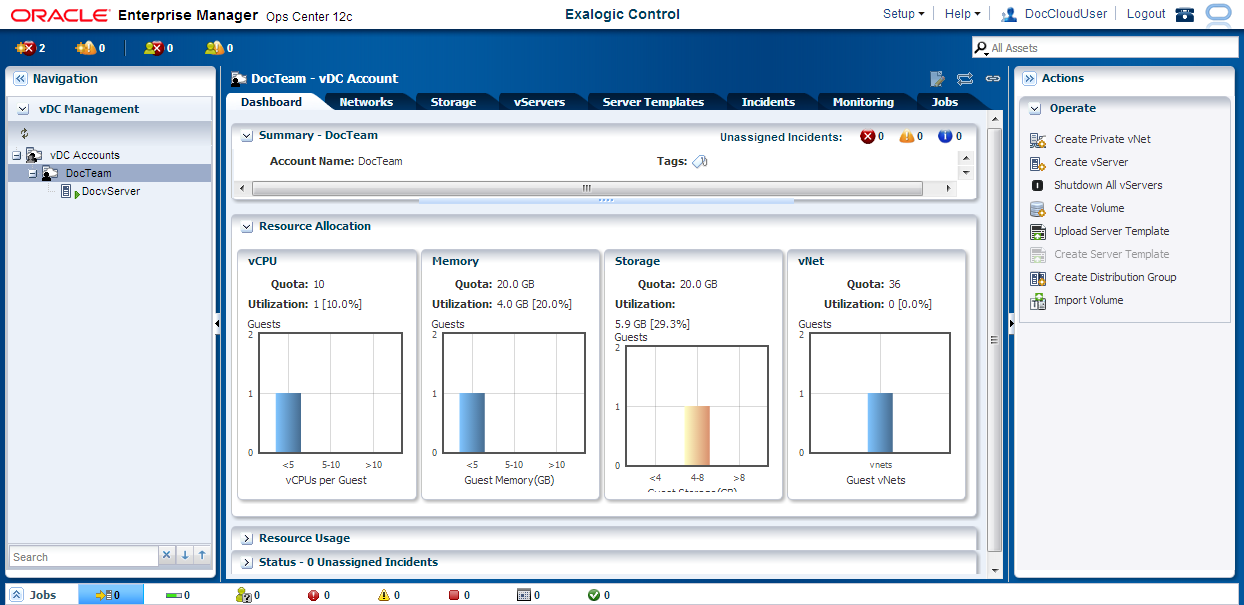
Uploading and Registering a Server Template
Server Templates contain the configuration of an individual vServer with its virtual disk. Templates can be of the format .tgz, .tar or other file types.
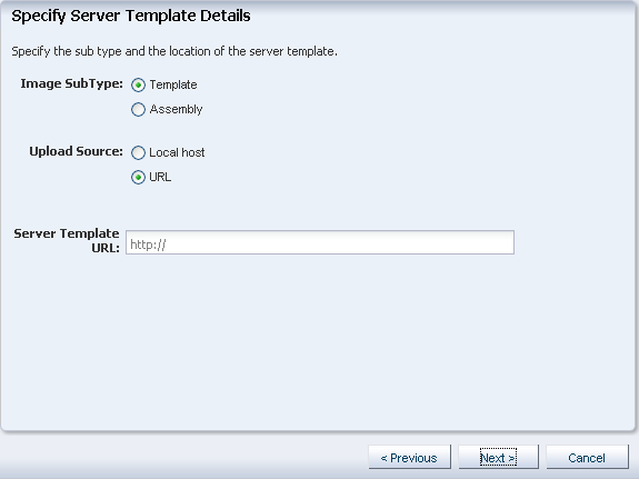
You can use HTTP, HTTPS, or FTP protocols to upload Server Templates from any network, including the external EoIB network, that is available to the VM hosting the Enterprise Controller component of Exalogic Control.
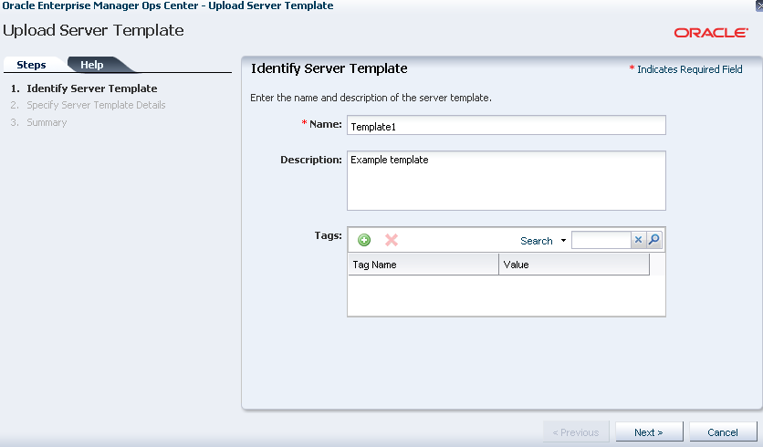
You can upload a Server Template to Exalogic Control as follows:
Making a Server Template Public
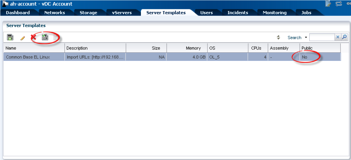
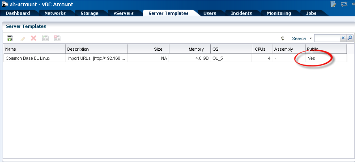
To make a server template available to all accounts in the vDC, you must make the template public. Private server templates are available to only the Cloud Users assigned to the account in which the server template was created.
After uploading a server template, complete the following steps to make it public:
Note:
To make a public template private, select the template in the list, click the Unregister Server Template icon in the toolbar just above the list of templates, and follow the on-screen instructions.
Creating Private vNets
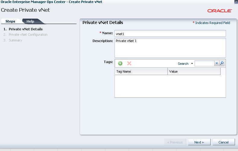
A private vNet is an IPoIB network within the Exalogic fabric that enables secure vServer-vServer communication.
You can create a private vNet in Exalogic Control as follows:
Creating Distribution Groups
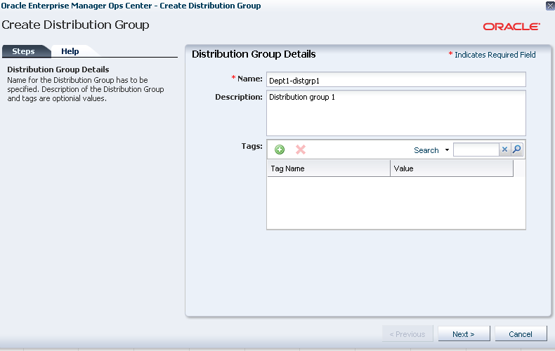
Create a Distribution Group in Exalogic Control as follows:
Note:
You cannot specify a distribution group for a set of vServers after vServer creation. For information about associating a vServer with a distribution group while creating the vServer, see step 17 in Creating vServers.
Creating Volumes
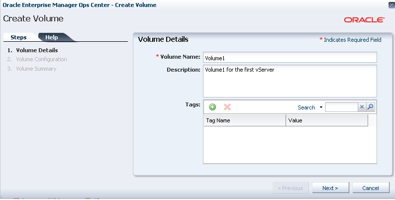
Volumes are disk images stored as virtual disks in the Oracle VM Manager repository.
To create a volume, complete the following steps:
Note:
After creating a volume, you must partition the volume using fdisk and create a file system using mkfs on the first vServer to which the volume is attached. On the vServer, the volume appears as a disk (/dev/hdX or /dev/xvdX). After the volume is partitioned and file system created, you must mount it using the /etc/fstab file on the vServer to make the filesystem accessible.
For information about attaching a volume to a vServer, see Creating vServers.
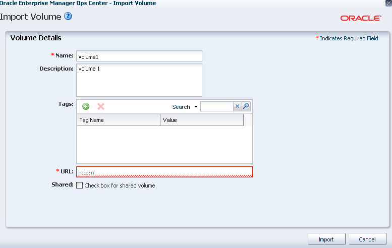
Importing Volumes
If you want to import a volume from an external URL instead of creating a volume, complete the following steps:
Creating vServers
Before you begin creating vServers, ensure that the following prerequisites are fulfilled:
-
Ensure that a vDC account has been created and users assigned to it as described in Establishing Cloud Accounts.
-
Ensure that the vDC account has the required network resources:
-
The required networks must be assigned to the account.
-
There must be sufficient unused IP addresses from the limit that was specified while assigning the networks to the account.
If the network-related prerequisites are not fulfilled, the
Cloud Adminuser must update the account, as described in Assigning Networks to an Account. -
-
If you want to use a custom vServer Type, ensure that it has been created as described in Creating vServer Types.
-
If you want to use a custom vServer template, ensure that the template has been uploaded to Exalogic Control as described in Uploading and Registering a Server Template.
-
Ensure that the required private vNets have been created as described in Creating Private vNets.
To create a vServer, do the following:
Note:
Use only Exalogic Control for creating vServers. Unless explicitly documented, do not use Oracle VM Manager to create vServers. Creating, cloning, deleting, or modifying vServers by using Oracle VM Manager will result in unsupported configurations.
-
Log in to the Exalogic Control as a user with the
Cloud Userrole. -
In the navigation pane on the left, click vDC Management.
Under vDC Accounts, click the name of your account, such as
Dept1.The vDC Account dashboard is displayed.
-
Click vServers on the top navigation bar.
Note:
To be able to create vServers, both the Sun Network QDR InfiniBand Gateway switches must be running. So before proceeding, check—with your Exalogic Systems Administrator—whether both the gateway switches are running.
-
Under vServers, click the + icon.
The Create vServer wizard starts.
-
In the vServer Name field, enter a name for the vServer to be created. For example,
vserver1.Note:
The name of a vServer need not be unique. To identify the Universally Unique Identifier (UUID) of a vServer, see the Domain Name field in the Dashboard tab of the vServer.
-
In the Description field, enter a brief description.
-
In the Number of vServers field, enter the number of vServers to be created. For example,
1. -
If you want to enable high availability for the vServer, leave the High Availability Support check box selected; otherwise, deselect it.
For more information about how vServer high availability works, see Managing High Availability of vServers.
-
Click Next.
The Server Template Selection screen is displayed.
-
Select one of the available Server Templates that you uploaded in Uploading and Registering a Server Template.
-
Click Next.
The vServer Type Selection screen is displayed.
-
Select a vServer Type and click Next.
The Attach Volumes screen is displayed.
-
Attach additional volumes, if required, to the vServer by selecting an available volume and clicking the right arrow. For example, attach
Volume1. -
Click Next.
The vNet Selection screen is displayed.
-
If you want to associate the vServer with one or more networks available for the account, select from the available networks.
After selecting the required networks, click Next.
Note:
-
The networks to which you want to associate the vServer must be assigned (by a
Cloud Adminuser) to the account and the required IP addresses must be provisioned, as described in Assigning Networks to an Account. -
If the vServer must have access to shares on the ZFS storage appliance, you must select the
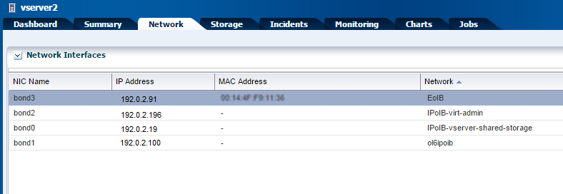
IPoIB-vserver-shared-storagenetwork and also (later) perform the procedure described in Setting Up Access to the ZFS Storage Appliance for a vServer. -
If you associate the vServer with two or more EoIB networks, then, for enabling access to the vServer from outside the machine through all the EoIB interfaces, you must configure advanced routing on the vServer, by using (for example) iproute2 or dynamic routing.
The Assign IP Address screen is displayed because you are creating a single vServer. If you chose to create multiple vServers by specifying the number of vServers, the IP address assignment is skipped. All IP addresses are allocated automatically.
-
-
Select an IP address allocation method: static IP, or automatic. If you select static IP, select the required IP address in the IP Address field. If you select automatic, you do not need to enter an IP address; it is selected from IP addresses available for the network.
Note:
If you select the static IP address option, ensure that you have allocated IP addresses for the network. For more information, see Allocating Virtual IPs for an Account
After assigning an IP address, click Next.
The Distribution Group Selection screen is displayed.
-
If necessary, select one of the available distribution groups in which the new vServer should be placed. Note that you cannot assign a vServer to a distribution group after creating the vServer.
Click Next.
The vServer Access screen is displayed.
-
If required, set up access for the vServer by specifying the path to the public key file. Alternatively, enter the public key in the Public Key field.
-
Click Next.
The Summary screen is displayed.
-
Review the summary screen, and click Finish to create the vServer (
vserver1).Note:
If a Create-vServer job is taking a long time, wait till the job either fails or is completed. Do not stop the job. If the job fails, do not run it again. Attempting to stop a job or run it again can corrupt the system, making it difficult to diagnose and recover.
-
Set the MTU to 64000 for each InfiniBand interface:
-
Log in to the vServer using SSH as the
rootuser. -
Verify the current MTU for
bond2by running theifconfigcommand.Note:
The steps in this procedure use
bond2as an example. This procedure should be repeated for all the InfiniBand interfaces.# ifconfig bond2 bond2 Link encap:InfiniBand HWaddr 80:58:08:CA:FE:80:00:00:00:00:00:00:00:00:00:00:00:00:00:00 inet addr:192.168.1.12 Bcast:192.168.1.255 Mask:255.255.255.0 UP BROADCAST RUNNING MASTER MULTICAST MTU:1500 Metric:1 RX packets:9 errors:0 dropped:0 overruns:0 frame:0 TX packets:7 errors:0 dropped:0 overruns:0 carrier:0 collisions:0 txqueuelen:0 RX bytes:504 (504.0 b) TX bytes:420 (420.0 b) -
Append the line
MTU=64000to theifcfgfile corresponding to thebond2interface:# echo MTU=64000 >> /etc/sysconfig/network-scripts/ifcfg-bond2
-
Verify whether the
MTU=64000line was added to theifcfg-bond2file:# cat /etc/sysconfig/network-scripts/ifcfg-bond2 | grep MTU MTU=64000 -
Find the slave interfaces for
bond2:# cd /etc/sysconfig/network-scripts # grep "MASTER=bond2" ifcfg-* | awk -F":" '{print $1}' ifcfg-ib0.8009 ifcfg-ib1.8009 -
Set the mode to
connectedfor both the slave interfaces of thebond2interface:# echo connected > /sys/class/net/ib0.8009/mode # echo connected > /sys/class/net/ib1.8009/mode
-
Perform steps 21.b through 21.f for the other InfiniBand interfaces.
-
Stop and start the vServer as described in Stopping vServers and Starting vServers.
-
After the vServer starts, log in again to the vServer using SSH as the
rootuser. -
Run the
ifconfigcommand for each InfiniBand interface, and verify that the output of the command displaysMTU:64000, as shown in the following example forbond2and its slave interfaces:# ifconfig bond2 | grep MTU UP BROADCAST RUNNING MASTER MULTICAST MTU:64000 Metric:1 # ifconfig ib0.8009 | grep MTU UP BROADCAST RUNNING SLAVE MULTICAST MTU:64000 Metric:1 # ifconfig ib1.8009 | grep MTU UP BROADCAST RUNNING SLAVE MULTICAST MTU:64000 Metric:1
-
Stopping vServers
To stop a vServer, do the following:
Note:
Do not use the xm destroy command or Oracle VM Manager to stop a vServer. Use only Exalogic Control.
- Log in to the Exalogic Control as a Cloud User.
- From the navigation pane on the left, click vDC Management.
- Under vDCs, expand your cloud such as
MyCloud. - Expand Accounts.
- Expand the name of your account, such as
Dept1. All the vServers in the account are displayed. - Select the vServer you wish to stop. The dashboard of the vServer is displayed.
- From the actions pane on the right, click Stop vServer. Wait till the job succeeds in the jobs pane.
Starting vServers
To start a vServer, do the following:
Note:
Do not use the xm create command or Oracle VM Manager to start a vServer. Use only Exalogic Control.
Managing High Availability of vServers
This section describes how high availability (HA) for guest vServers works and can be managed in a vDC running on Exalogic. In this context, HA is the ability to automatically restart vServers that may be affected by an unexpected outage such as a vServer crash or a compute node failure. This feature is available starting from release 2.0.4.0.0 of the Exalogic Elastic Cloud Software.
Note:
Currently, high availability for Exalogic Control VMs is not supported. For information about restoring failed Exalogic Control VMs, contact Oracle Support.
This section contains the following topics:
How High Availability Works for Guest vServers
Figure 9-13 is a flowchart depicting how the vServer HA feature works.
Note:
You must ensure that there are sufficient CPU and memory resources on compute nodes in the vDC for a successful migration of the vServers affected by an unexpected outage. If none of the compute nodes has sufficient resources, the failed vServer is not migrated.
Figure 9-13 Guest vServer High-Availability Process
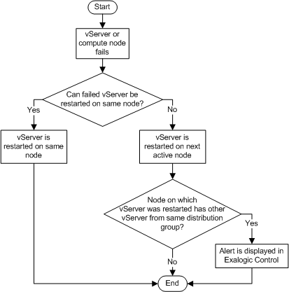
Description of "Figure 9-13 Guest vServer High-Availability Process"
Description of the HA Flow for Guest vServers
-
If an HA-enabled vServer crashes, the failed vServer is restarted automatically on the same compute node.
However, if the compute node on which the vServer was originally running has failed or does not have enough resources, the vServer is started on the next active compute node in the same server pool. Note that, if there are no active compute nodes in the server pool, the failed vServer is not started.
-
If the compute node on which a failed vServer is restarted already hosts any vServer that belongs to the same distribution group as that of the restarted vServer, an alert is displayed for the account to which the distribution group belongs in the Incidents tab of Exalogic Control.
To resolve this distribution-group violation, the
Cloud Usershould stop the vServer and then start it again as described in Stopping vServers and Starting vServers. The vServer is then restarted on a compute node that does not host any vServer from the same distribution group. If such a compute node is not available, the vServer is not started.
Enabling and Disabling High Availability for Guest vServers
HA for guest vServers is enabled by default when the vServers are created. If the vServers fail, they are automatically restarted on the same compute node, or migrated to a different compute node if the original node is down, as described in How High Availability Works for Guest vServers.
If required, the Cloud User can, while creating vServers, disable HA, as described in Creating vServers.
Migration of vServers to a different compute node (if the original node is down) can be disabled and re-enabled by Cloud Users by using the Disable vServer HA and Enable vServer HA actions in Exalogic Control, as shown in Figure 9-14.
-
Figure 9-14 Enabling and Disabling HA for Guest vServers
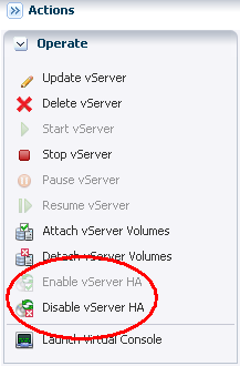
Description of "Figure 9-14 Enabling and Disabling HA for Guest vServers"
Note:
The state of the Enable vServer HA or Disable vServer HA items in the Actions pane indicates whether HA is currently enabled for a vServer. If Enable vServer HA is clickable, then HA is currently disabled for the vServer. If Disable vServer HA is clickable, then HA is currently enabled for the vServer. In addition, in the vServers tab of any account, you can view the HA state of a vServer by clicking the Status icon corresponding to the vServer.
Attaching Volumes to a vServer
You can attach a volume to a vServer as follows:
- Log in to the Exalogic Control as a Cloud User.
- In the navigation pane on the left, click vDC Management.
- Under vDC Accounts, expand the name of your account, such as
Dept1. All the vServers in the account are displayed. - Select the vServer (for example,
vserver2) to which you wish to attach a volume. Thevserver2dashboard is displayed. - From the actions pane on the right, click Stop vServer. Wait till the job succeeds in the jobs pane.
- From the actions pane on the right, click Attach vServer Volumes. The Attach vServer Volumes wizard is displayed.
- Select the volume you wish to attach to
vserver2. - Click the right arrow icon.
- Click Next. The confirmation screen is displayed.
- Click Finish. Wait till the job succeeds in the jobs pane.
- From the actions pane on the right, click the Start vServer button to restart the vServer.
Detaching Volumes from a vServer
You can detach a volume from a vServer as follows:
- Log in to the Exalogic Control as a Cloud User.
- In the navigation pane on the left, click vDC Management.
- Under vDC Accounts, expand the name of your account, such as
Dept1. All the vServers in the account are displayed. - Select the vServer (for example,
vserver2) from which you wish to detach a volume. Thevserver2dashboard is displayed. - From the actions pane on the right, click Stop vServer. Wait till the job succeeds in the jobs pane.
- From the actions pane on the right, click Detach vServer Volumes. The Detach vServer Volumes wizard is displayed.
- Select the volume you wish to detach from
vserver2. - Click the right arrow icon.
- Click Next. The confirmation screen is displayed.
- Click Finish. Wait till the job succeeds in the jobs pane.
- From the actions pane on the right, click the Start vServer button to restart the vServer.
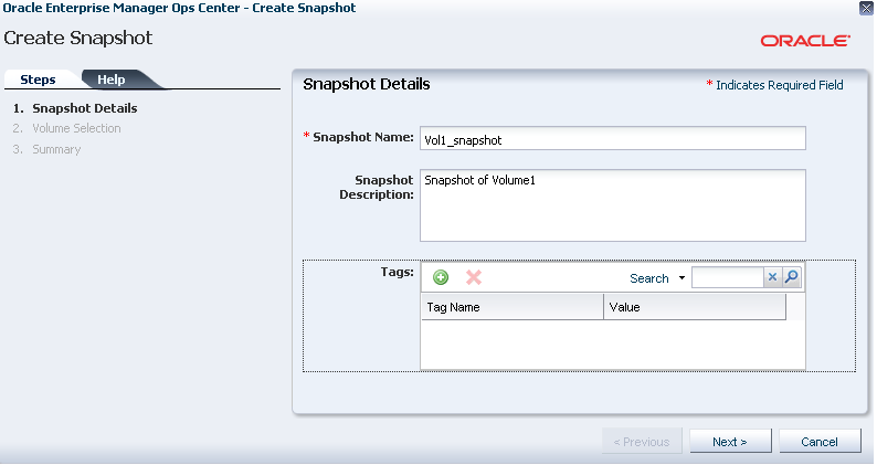
Creating a Snapshot from a Volume
This section describes how to create a snapshot from a volume attached to a vServer. It contains the following topics:
Creating a Snapshot from a Volume (EECS 2.0.4.x.x or Earlier)
In EECS release 2.0.4.x.x (or earlier), you can create a snapshot from a volume attached to a vServer, as follows:
