Table of Contents
- 7.1. Open an Existing EER Model
- 7.2. Create new EER Model
- 7.3. Create EER Model from Existing Database
- 7.4. Create EER Model from SQL Script
- 7.5. Model Editor
- 7.6. EER Diagram Editor
- 7.7. Working with Models
- 7.8. Modeling Tutorials
- 7.9. Printing
- 7.10. MySQL Workbench Schema Validation Plugins (Commercial Version)
- 7.11. Customizing DBDoc Model Reporting Templates
MySQL Workbench provides extensive capabilities for creating and manipulating database models. Some of these capabilities are listed here:
Create and manipulate a model graphically.
Reverse engineer a live database to a model.
Forward engineer a model to a script or live database.
Create and edit tables and insert data.
This is not an exhaustive list. These, and additional data modeling capablities, are discussed in the following sections.
The Home screen is the typical starting point for work with data modeling. In the Data Modeling section of the Workspace you can use the action items there to create and manage models, forward and reverse engineer, and compare and synchronize schemata. These action items are listed below:
Open an Existing EER Model
Open an Existing EER Model (icon)
Create new EER Model
Create EER Model from Existing Database
Create EER Model from SQL Script
These action items are described in the following sections.
Clicking this action item launches a file browser. You can then select the model file you wish to load. A new MySQL Model tab will then be created, and your model displayed.
Open an Existing EER Model (icon)
If you have already created one or more model files you can simply double-click the item of the model you wish to load. A new MySQL Model tab will be created, and your model displayed.
You can read more about modeling in the section Section 7.5, “Model Editor”.
Clicking this action item will launch a new MySQL Model tab, with a blank model ready for you to work on.
You can read more about modeling in the section Section 7.5, “Model Editor”.
The purpose of this action item is to allow you to create an EER Model from an existing live database. Clicking this action item launches the Reverse Engineer Database. This is a multi-stage wizard that enables you to select a connection to a live server, and select the schema and objects you wish to reverse engineer into your new model. This is a convenient way to see how an existing database is structured.
For further information on reverse engineering see Section 7.7.9.2, “Reverse Engineering a Live Database”.
The purpose of this action item is to allow you to create a model from a SQL Create script. Such a script may have been created by hand or may be as a result of reverse engineering an existing database to generate the script, which may then be modified according to requirements. Clicking this action item launches the Reverse Engineer SQL Script wizard. This is a multi-stage wizard that enables you to select the script you want to create your model from.
For further information see Section 7.7.9.1, “Reverse Engineering Using a Create Script”.
When the Model Editor is executed from the Home Screen, the MySQL Model page is displayed. The MySQL Model page has three main panels: Description Editor, User Types List/History panel, and the main panel - the Model Overview panel. The Description Editor and User Types List/History panel are contained within the Sidebar. The Sidebar is located on the left by default, but can be relocated to the right using a setting in the Workbench Preferences dialog.
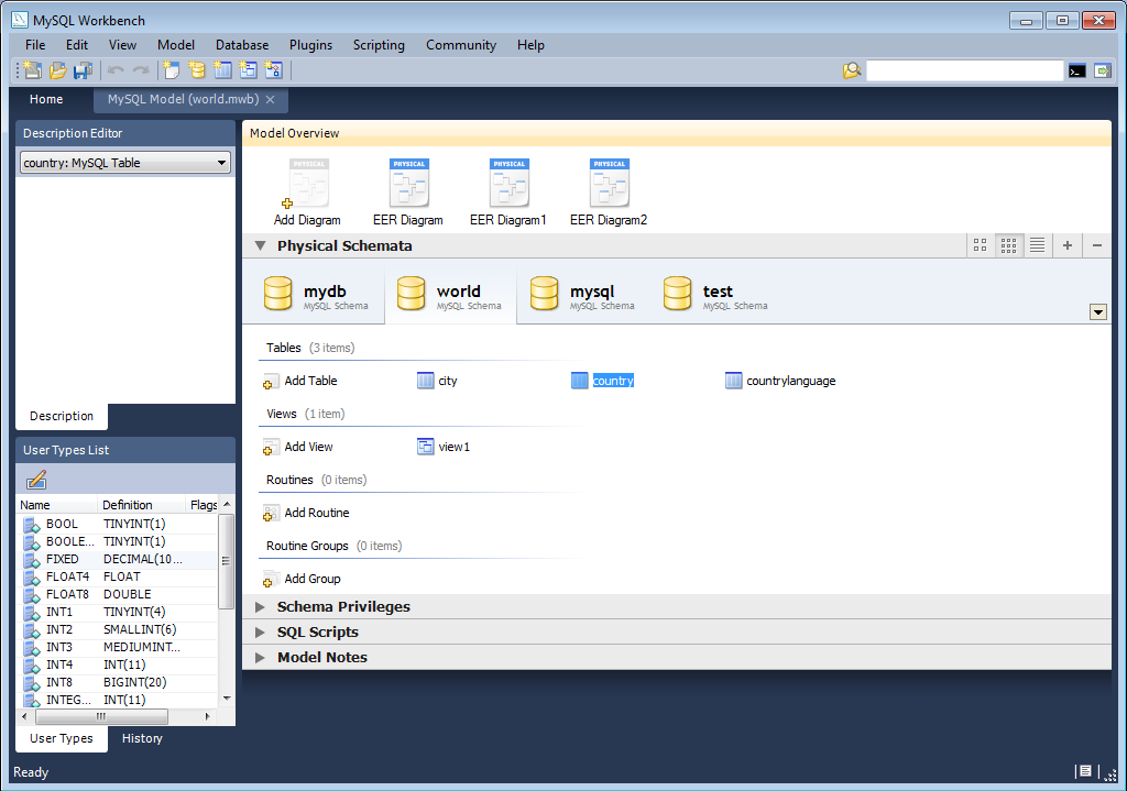
The sections within the Model Overview panel are:
EER Diagrams
Physical Schemata
Schema Privileges
SQL Scripts
Model Notes
For each of these sections objects can be added to a project by clicking the appropriate add object icon. You may also rename, edit, cut, copy, or delete objects on this page by right-clicking. Doing this opens a pop-up menu.
The sections within the MySQL Model page are discussed in the following sections.
Some menu options are not available in the OSS version of this application, and are only available in the Standard Edition. This is indicated where applicable.
Use this menu item to open a project, begin a new project, or save
a project. Choosing opens the default
schema, mydb. Choosing opens a file dialog box with the default file type
set to MySQL Workbench Models (MWB). To display a list of recently
opened MWB files, choose the menu
option. The keyboard command to create a new project is
Ctrl N and the command to open
an existing project is Ctrl O.
To close the currently active MySQL Model or
EER Diagram tab, use the option. You can also do this from the keyboard by
pressing Ctrl W. To reopen the
MySQL Model tab, see
Section 7.5.1.3, “The View Menu”. To reopen an EER
Diagram tab, double-click the EER
Diagram icon in the EER Diagrams
section of the MySQL Model page.
Use the or menu options to save a model. When you save a model
its name appears in the title bar of the application. If you have
made changes to a project and have not saved those changes, an
asterisk appears in the title bar following the model name. When
you save a model it is saved as a MySQL Workbench file with the
extension mwb.
Use the menu option to import a MySQL
data definition (DDL) script file, one created by issuing the
command mysqldump --no-data,
for example. If the script does not contain a CREATE
db_name; statement, the
schema objects will be copied to the default schema,
mydb. If the script creates a database, a new
tab bearing the database name is added to the Physical
Schemata section of the MySQL Model
page. If the script contains data, it will be ignored. Importing a
DDL script is discussed in detail in
Section 7.7.9.1, “Reverse Engineering Using a Create Script”.
Under the menu option you can also
import DBDesigner4 files.
There are variety of options under the menu item. You may generate the SQL statements necessary to create a new database or alter an existing one. These menu items are discussed in detail in Section 7.7.10.1, “Forward Engineering Using SQL Scripts”.
Using the menu item you can also export
an EER diagram as a PNG, SVG, PDF or Postscript file. For an
example of a PNG file see Figure 7.45, “The sakila EER Diagram”.
The menu item enables you to set the paper size, orientation and margins for printing purposes.
The print options are only enabled if the EER Diagrams tab is selected. You have the choice of printing your model directly to your printer, printing it as a PDF file, or creating a PostScript file. For more information see Section 7.9, “Printing”.
The printing options are only available in commercial versions of MySQL Workbench.
Use the menu option to set the following properties of your project:
Name: Defaults toMySQL ModelVersion: The project version number.Author: The project author.Project: The project name.Created: Not editable, determined by the MWB file attributes.Last Changed: Not editable, determined by the MWB file attributes.Description: A description of your project.
Under this menu item find the options for cutting, copying, and pasting. These actions can also be performed using the Ctrl X, Ctrl C, and Ctrl V key combinations. Undo a deletion using the option. The Ctrl Z key combination can also be used to undo an operation. It is also possible to carry out a operation using either the menu item, or the key combination Ctrl Y.
Also find a menu item for removing the currently selected object. The text description for this menu item changes to reflect the name of the currently selected object. The keyboard command for this action is Ctrl Delete. You can also right click an object and choose the delete option from the pop-up menu.
The menu item behaves differently depending upon circumstances. For instance, if an EER Diagram is active and a table on the canvas is the currently selected object, a dialog box may open asking whether you want to remove the table from the canvas only or from the database as well. For setting the default behavior when deleting from an EER Diagram see Section 5.4.4, “The Model Tab”.
If the MySQL Model page is active, the
selected object will be deleted from the catalog and there will
be no confirmation dialog box.
Choose to edit the currently selected object. You can also perform edits in a new window by selecting . The keyboard shortcut for is Ctrl E and Ctrl Shift E for .
The option has the following submenus:
(Keyboard shortcut, Ctrl A): Select all the objects on the active EER diagram.
(Objects of the same type): Use this option to find objects similar to the currently selected object.
: Use this option to find all the objects connected to the currently selected object.
These menu items are only active when an EER Diagram tab is selected. The and the menu options are disabled if no object is currently selected on an EER diagram.
When multiple objects have been selected using one of these menu options, you can navigate between selected items by choosing the or menu options.
Selecting items changes some of the menu options. If only one object is selected, that object's name appears after the , and menu options. If more than one object is selected, these menu items show the number of objects selected.
The menu item displays a sub-menu with the following menu items:
: Takes you to the toolbar search box. You can look for objects in the current view. Find can locate objects in the Model view, the EER Diagram view, and also in the Catalog palette.
: Finds the next occurrence of the object.
: Finds the previous occurrence of the object.
: Displays the Search and Replace dialog. This is currently only for use with the SQL Editor, to allow you to quickly search and replace script code items.
The Standard Edition of MySQL Workbench includes a more advanced Find facility:
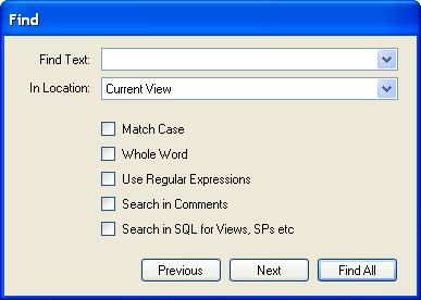
You can search the following locations:
Entire Model: Search the entire model.
Current View: Search the current view only. This may be the
MySQL Modelpage.All Views: Search the
MySQL Model Pageand all EER diagrams.Database Objects: Search database objects only.
Selected Figures: Search the currently selected objects. This feature only works for EER diagrams.
Enter the text you wish to search for in the Find Text drop down list box. You may also select any or all of the following check boxes:
Match Case
Whole Word
Use Regular Expression
Search in Comments
Search in SQL for Views, SPs etc.
Any text you enter into the Find Text drop down list box is retained for the duration of your session. Use the or buttons to find occurrences of your search criterion.
Clicking the button opens a Find Results window anchored at the bottom of the application. If you wish, you may undock this window as you would any other.
Use this window to navigate to objects. For example, double
clicking the Description of an object located
on an EER diagram navigates to the specific diagram and selects
the object. Notice that the properties of the object are
displayed in the Properties palette.
The Find dialog window can also be opened
using the Ctrl F key
combination. Use Ctrl G to
find the next occurrence and Ctrl
Shift G to find a previous
occurrence. Close the Find dialog window by
clicking the in the top right corner or
by pressing the Esc key.
This menu option enables you to set global preferences for the MySQL Workbench application.
For further information see Section 5.4, “Workbench Preferences”.
The Options available under this menu item are:
: Selects the Home screen.
: Open the
Model Navigatorpalette: Open the
Catalogpalette: Open the
Layerspalette: Open the
User Datatypespalette: Open the
Descriptionpalette: Open the
Propertiespalette: Open the
Historypalette
These menu options provide a means for opening the windows associated with these options.
: Use this option to display the console output. The keyboard shortcut for this menu item is Ctrl F2.
: Open the GRT shell. For more information about the GRT shell see Section 9.5, “The Workbench Scripting Shell”. The keyboard shortcut for opening the GRT shell is Ctrl F3.
: Reset all windows to their default layout.
: The default level of detail of an EER diagram.
: Zoom in on an EER diagram.
: Zoom out from an EER diagram.
The ability to zoom in on an EER diagram is also available using the slider tool in the
Model Navigatorpalette. See Section 7.5.8, “The Model Navigator Panel”.: Use this option to bookmark an object. From the keyboard select the object you wish to bookmark and use the key combination Ctrl Shift and the number of the marker (1 through 9). You may create up to nine markers.
: Return to a marker. From the keyboard use the Ctrl key and the number of the marker.
The Arrange menu option applies only to objects
on an EER diagram canvas and is only visible if an EER diagram
view is active. The options under this menu item are as follows:
: Align items on the canvas to the grid lines.
: Use this option to bring objects to the foreground.
: Use this option to move objects to the background.
: Use this option to center objects on the canvas.
: Use this option to automatically arrange objects on the canvas.
: This option expands an object on an EER diagram. For example, if a table has a long column name that is not fully displayed, using this menu option will expand the table making the column visible. This menu item is not enabled until an object is selected.
: Use this option to expand all objects on an EER diagram. This option will display a table's columns if the object notation supports expansion. Some object notations, such as
Classic, do not allow for expansion or contraction. Indexes will not automatically be expanded unless they were previously expanded and have been collapsed using the menu option.: Undo the operation performed by .
The menu options available under the Model menu
item are as follows:
Add Diagram: Create a new EER Diagram. The keyboard shortcut is Ctrl T.
Create Diagram From Catalog Objects: Create an EER diagram from all the objects in the catalog.
DBDoc – Model Reporting...: For information on using this menu option see Section 7.5.1.5.1, “The DBDoc Model Reporting Dialog Window (Commercial Version)”. Commercial version only.
User Defined Types: Choosing this menu option presents you with a dialog box, allowing you to add and delete user defined data types.
Object Notation: The items available under this option are discussed in Section 7.5.1.5.3, “The Object Notation Menu Options”.
Relationship Notation: The items available under this option are discussed in Section 7.5.1.5.4, “The Relationship Notation Menu Option”.
Diagram Properties and Size: Choosing this menu option opens a diagram size dialog box. Use this dialog box to adjust the width or height of the canvas. The unit of measure is pages; the default value is two.
When you have tables with numerous columns, use this menu option to increase the size of the EER.
Validation: The items available under this option are discussed in Section 7.5.1.5.2, “The Validation Menu Options (Commercial Version)”. Commercial version only.
Model Options: Set options at the model level. These options should not be confused with the options that are set globally for the Workbench application, and which are now referred to as Workbench Preferences. The available model options are a subset of the Workbench Preferences options.
For more information on Workbench Preferences see Section 5.4.4, “The Model Tab”.
This dialog window is found by navigating to the menu item and choosing the option.
The option is not available in the MySQL Workbench OSS version.
Use this dialog window to set the options for creating documentation of your database models.
You can about this menu item in more detail in the following section The DBDoc Model Reporting Dialog Window.
Under the menu option there are two validation options, and . Use these options for general validation and MySQL-specific validation of the objects and relationships defined in your model.
These options are not available in the MySQL Workbench OSS version.
Under the option the menu items are:
: Perform all the validation options available
: Check for objects with no content, for example a table with no columns
: Check the efficiency of tables, for example a table with no primary key defined
: Check for duplicate identifiers, for example two tables with the same name
: Check for consistent naming conventions
: Check, for example, that a foreign key does not reference a nonprimary key column in the source table
Under the option the menu items are:
: Perform all the validation options available
: Check for invalid references, for example, a table name longer than the maximum allowed
: Check for correct SQL syntax
: Check for objects with the same name
For detailed information about validation see Section 7.10, “MySQL Workbench Schema Validation Plugins (Commercial Version)”.
The options under the menu apply exclusively to an EER diagram. They are grayed out if an EER diagram tab is not selected.
The menu options are as follows:
: Display table columns, indexes, and triggers.
: Show only a table's columns.
: Show only columns that are primary and foreign keys.
: Similar to the
Workbench (Simplified)style showing only the table's columns.: The ICAM DEFinition language information modeling style.
The object notation style that you choose persists for the duration of your MySQL Workbench session and is saved along with your model. When MySQL Workbench is restarted, the object notation reverts to the default.
If you plan to export or print an EER diagram be sure to decide on a notation style first. Changing notation styles after objects have been placed on a diagram can significantly change the appearance of the diagram.
The options under the menu apply exclusively to an EER diagram. They are grayed out if an EER diagram tab is not selected. The menu options are as follows:
: The default modeling style. For an example see Figure 7.42, “Adding Tables to the Canvas”.
: Uses a diamond shape to indicate cardinality.
: Universal Modeling Language style.
: The ICAM DEFinition language information modeling method
To view the different styles, set up a relationship between two or more tables and choose the different menu options
The relationship notation style that you choose persists for the
duration of your MySQL Workbench session and is saved along with
your model. When MySQL Workbench is restarted, the relationship
notation reverts to the default, the Crow's
Foot style.
If you plan to export or print an EER diagram be sure to decide on a notation style first. Changing notation styles after objects have been placed on a diagram can significantly change the appearance of the diagram.
There are several options under the menu option:
: Launche the SQL Editor, which enables you to create SQL code and execute it on a live server. For more information see Section 6.7, “SQL Editor”.
: Launche the Manage DB Connections dialog, which enables you to create and manage multiple connections. For more information see Section 6.6, “Manage DB Connections Dialog”
: Create a model from an existing database. For more information, see Section 7.7.9.2, “Reverse Engineering a Live Database”.
: Create a database from a model. For more information, see Section 7.7.10.2, “Forward Engineering to a Live Server”.
: Synchronize your database model with an existing database. For more information, see Section 7.7.10.3, “Database Synchronization”.
: Compare your schema model with a live database or a script file. Section 7.7.10.4, “Creating a Catalog Diff Report”.
The menu option lists any plugins that you may have installed. For more information about this menu option see Section 9.3, “Plugins”.
This menu currently has three items:
: Launches the MySQL Workbench Scripting Shell.
: Executes the specified script.
: Enables you to load and install a plugin/module file.
The menu option offers the following choices:
Use these menu options to go online and learn more about MySQL Workbench.
The menu option offers the following choices:
: Open a window showing the MySQL Workbench documentation. Read, search, or print the documentation from this window.
: Open your default browser on the MySQL Workbench website and check for a newer version.
: Update to the latest version.
: Open your default browser on the MySQL website home page.
: Open your default browser on the MySQL Workbench product page.
: Information about your system, useful when reporting a bug. For more information, see Section 7.5.1.10.1, “System Info”.
: Open your default browser on the MySQL bug report page.
: Open your default browser to see a list of current bugs.
: Show the MySQL Workbench
Aboutwindow.
Use these menu options to go online and learn more about MySQL Workbench.
Use the menu option to determine information about your system. This option is especially useful for determining your rendering mode. Sample output follows.
read_mysql_cfg_file C:\Program Files\MySQL\MySQL Server 5.1\my.ini
[('tmp_table_size', '9M'),
('myisam_sort_buffer_size', '18M'),
('table_cache', '256'),
('read_rnd_buffer_size', '256K'),
('port', '3306'), ('max_connections', '100'),
('innodb_buffer_pool_size', '18M'),
('myisam_max_sort_file_size', '100G'),
('sql-mode', '"STRICT_TRANS_TABLES,NO_AUTO_CREATE_USER,NO_ENGINE_SUBSTITUTION"'),
('basedir', '"C:/Program Files/MySQL/MySQL Server 5.1/"'),
('default-character-set', 'latin1'),
('datadir', '"C:/ProgramData/MySQL/MySQL Server 5.1/Data/"'),
('innodb_log_buffer_size', '1M'),
('innodb_log_file_size', '10M'),
('innodb_thread_concurrency', '8'),
('read_buffer_size', '64K'),
('innodb_additional_mem_pool_size', '2M'),
('thread_cache_size', '8'),
('innodb_flush_log_at_trx_commit', '1'),
('query_cache_size', '0'),
('sort_buffer_size', '256K'),
('default-storage-engine', 'INNODB'),
('key_buffer_size', '11M')]
MySQL Workbench OSS for Windows version 5.2.8
Cairo Version: 1.8.6
Rendering Mode: GDI requested (create a diagram to confirm)
OpenGL Driver Version: Not Detected
OS: unknown
CPU: Intel(R) Core(TM)2 Duo CPU T9300 @ 2.50GHz, 1.0 GB RAM
Video adapter info:
Adapter type: VirtualBox Graphics Adapter
Chip Type: VBOX
BIOS String: Version 0xB0C2 or later
Video Memory: 12288 KBThe MySQL Workbench toolbar is found immediately below the menu bar. The following tools always appear on the toolbar:
The new document icon: Click this icon to create a new document
The folder icon: Click this icon to open a MySQL Workbench file (MWB)
The save icon: Click this icon to save the current MySQL Workbench project
The right and left arrows: Click the left arrow to perform an “Undo” operation. Click the right arrow to perform a “Redo” operation.
Other tools appear on the toolbar depending upon the context.
When an EER diagram canvas is selected, the following icons appear to the right of the arrow icons:
The toggle grid icon: Used for turning the grid on and off
The grid icon: Used for aligning objects on the canvas with the grid
The toolbar also changes depending upon which tool from the vertical toolbar is active. These tools are discussed in Section 7.6.1, “The Vertical Toolbar”.
If the Table tool is active, drop down list
boxes of schemata, engine types and collations appear on the
toolbar. The table properties can then be modified using the
Properties Editor.
When an object is selected the object's properties, such as color, can be changed in the Properties Editor.
Use the Add Diagram icon in this area to create
EER diagrams. When you add an EER diagram a new tab appears below
the toolbar. Use this tab to navigate to the newly created EER
diagram. EER Diagrams are discussed in depth in
Section 7.6, “EER Diagram Editor”.
The Physical Schemata panel of the
MySQL Model page shows the active schemata and
the objects that they contain.
Expand and contract the Physical Schemata
section by double-clicking the arrow on the left of the
Physical Schemata title bar. When the
Physical Schemata section is expanded, all the
schemata that are currently loaded are displayed.
Each schema shows as a tab; a specific schema is selected by
clicking its tab. When MySQL Workbench is first opened a default
schema, mydb is selected. You can start working
with this schema or you can load a new MySQL Workbench Models
(MWB) file.
There are a variety of ways to add schema to the Physical
Schemata panel. You can open an MWB file, reverse
engineer a MySQL create script, or, if you are using a commercial
version of MySQL Workbench, you can reverse engineer a database by
connecting to a MySQL server.
You can also add a new schema by clicking the
button on the top right of the
Physical Schemata panel. To remove a schema,
click its tab and use the button found to
the immediate left of the button. To the
left of these buttons are three buttons that control the way
database object icons are displayed. The left-most button displays
database objects as large icons, the next button to the right
displays small icons in multiple rows, and the last button
displays small icons in a single list.
The Physical Schemata panel is divided up
into the following sections:
Tables
Views
Routines
Routine Groups
Each section contains the specified database objects and an icon used for creating additional objects.
Any database objects added to an EER diagram canvas also show up
in the Physical Schemata section. For
information about adding objects to an EER diagram canvas see
Section 7.6, “EER Diagram Editor”.
The Privileges panel of the MySQL
Model page is used to create users for your schemata and
also to define roles —.
The Schema Privileges panel is divided up into
the following sections:
Users
Roles
The following image displays the Schema
Privileges section of the MySQL Model
tab.
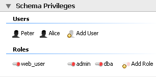
To add a role, double-click the Add Role
icon. Doing this creates a role with the default name
role1. Right-clicking a role opens a pop-up
menu with the following options:
': Cut the role
': Copy the role
: Open the role editor.
: Open the role editor in a new editor window.
': Remove the role
: Currently not implemented.
To rename a role, simply click the role name and you will then be able to edit the text.
All roles that have been defined are listed under
Roles on the left side of the role editor.
Double-clicking a role object opens the role editor docked at
the bottom of the screen.
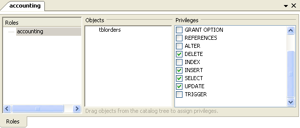
Select the role that you wish to add objects to. You may drag
and drop objects from the Physical Schemata
to the Objects section of the role editor. To
assign privileges to a role select a role from the
Roles section and then select an object in
the Objects section. In the
Privileges section check the rights you wish
to assign to this role. For example, a
web_user role might have only
SELECT privileges and only for database
objects exposed through a web interface. Creating roles can make
the process of assigning rights to new users much easier.
To add a user double-click the Add User icon.
Doing this creates a user with the default name
user1. Double-clicking this user opens the
user editor docked at the bottom of the application.
In the User Editor, set the user's name using
the Name text box and set the password
using the Password text box. Assign one
role or a number of roles to the user by selecting the desired
roles from the text area on the right and then clicking the
button. Roles may be revoked by
moving them in the opposite direction.
Right-clicking a user opens a pop-up menu. These options function as described in Section 7.5.5.1, “Adding Roles”.
The two remaining panels on the MySQL Model
page are SQL Scripts panel and the
Model Notes panel.
Use the SQL Scripts panel to load and modify
SQL scripts. If you created your project from an SQL script and
plan to create an ALTER script, you may want to
add the original script here, since it will be needed to create an
ALTER script. For more information, see
Section 7.7.10.1.2, “Altering a Schema”.
Use the Model Notes panel to write project
notes. Any scripts or notes added will be saved with your project.
Use the History palette to review the actions
that you have taken. Left-clicking an entry opens a pop-up menu
with the option, . Choose this option to select a single entry.
You can select multiple contiguous entries by pressing the
Shift key and clicking the entries you wish to
copy. Select noncontiguous entries by using the
Ctrl key.
Only actions that alter the MySQL model or change an EER diagram
are captured by the History palette.
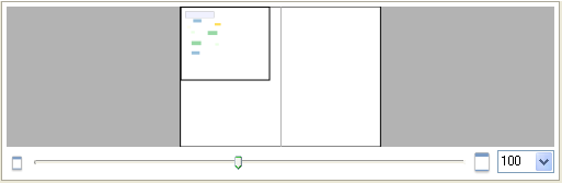
Docked at the top left of the application is the Model Navigator, or Bird's Eye panel. This panel gives you an overview of the objects placed on an EER diagram canvas and for this reason it is most useful when an EER diagram is active. Any objects that you have placed on the canvas should be visible in the navigator.
The Model Navigator shows the total area of an EER diagram. A black rectangular outline indicates the view port onto the visible area of the canvas. To change the view port of an EER diagram left click this black outline and drag it to the desired location. You can zoom in on selected areas of an EER diagram by using the slider tool at the bottom of this window. The dimensions of the view port change as you zoom in and out. If the slider tool has the focus you can also zoom using the arrow keys.
The default size of the Model Navigator is two
pages. To change this use the ,
menu option.
The Catalog Tree palette shows all the schemata
that are present in the Physical Schemata
section of the MySQL Model page. Expand the
view of the objects contained in a specific schema by clicking the
button to the left of the schema name.
Doing this displays the following folder icons:
Tables
Views
Routine Groups
Expand each of these in turn by clicking the button to the left of the folder icon.
Selecting an object in this palette, displays its properties in
the Properties palette, which can be found in
the lower left corner of the screen.
The Catalog Tree palette is primarily used to drag and drop objects onto an EER diagram canvas.
On Linux, there is a quirk in the GTK tree control, where a simple click always generates a new selection. If you want to drag multiple objects from the Catalog Tree to the EER diagram canvas, you need to perform the operation as follows:
Click first item in tree.
Hold shift and click last item and do not release the shift key.
Keep the shift key depressed and commence the dragging operation.
Release the shift key before you release the mouse button to successfully drop selected objects onto the canvas.
This also applies to use of the Ctrl key when selecting multiple non-adjacent elements in the Catalog Tree.
You can toggle the sidebar on and off using the Toggle Sidebar button, which is located in the top right of the application.
This palette shows all the layers and figures that have been
placed on an EER diagram. If a layer or figure is currently
selected, an X appears beside the name of the
object and its properties are displayed in the
Properties palette. This can be especially
useful in determining which objects are selected when you have
selected multiple objects using the various options under the
menu option. For more information on
this topic see Section 7.5.1.2, “The Edit Menu”.
Selecting an object in the Layers palette also
adjusts the view port to the area of the canvas where the object
is located.
In some circumstances you may want to make an object on an EER
diagram invisible. To do this, select the object and, in the
Properties palette, set the
visible property to False.
The Layer palette provides an easy way to
locate an object, such as a relationship, that has been set to
hidden. Open the Layers
palette and select the object by double-clicking it. You can
then edit the object and change its visibility setting to
Fully Visible.
The Properties palette is used to display and
edit the properties of objects on an EER diagram. It is especially
useful for editing display objects such as layers and notes.
All objects except connections have the following properties except as noted:
color: The color accent of the object. The color of the object is displayed here as is its hexadecimal value. Change the color of the object by changing this value. Only characters that are legal for hexadecimal values may be entered. You can also change the color by clicking the button. This opens a color changer dialog box.description: Applicable to layers only. A means of documenting the purpose of a layer.expanded: This attribute applies to objects such as tables that can be expanded to show columns, indexes, and triggers.height: The height of the object. Depending upon the object, this property may be read only or read/write.left: The number of pixels from the object to the left side of the canvas.locked: Whether the object is locked or not. The value for this attribute is eithertrueorfalse.manualSizing: Whether the object has been manually sized or not. The value for this attribute is eithertrueorfalse.name: The name of the object.top: The number of pixels from the object to the top of the canvas.visible: This property controls whether an object shows up on the canvas or not. Use‘1’for true and‘0’for false. It is currently only used for relationships.width: The width of the object. Depending upon the object, this property may be read only or read/write.
In addition to the properties listed above, tables also have the following properties:
indexesExpanded: This property determines whether indexes are displayed when a table is placed on the canvas. Use‘1’for true and‘0’for false.triggersExpanded: This property determines whether triggers are displayed when a table is placed on the canvas. Use‘1’for true and‘0’for false.
For a discussion of the properties of connections see Section 7.7.2.3, “The Properties of a Connection”.
EER diagrams are created by double-clicking the Add
Diagram icon. You may create any number of EER diagrams
just as you may create any number of physical schemata. Each EER
diagram shows as a tab below the toolbar; a specific EER diagram is
selected by clicking its tab.
Clicking an EER diagram tab navigates to the canvas used for
graphically manipulating database objects. On the left side of this
page is the Vertical Toolbar.
The vertical toolbar shows on the left sidebar when an EER diagram tab is selected. The tools on this toolbar assist in creating EER diagrams.
Clicking a tool changes the mouse pointer to a pointer that resembles the tool icon, indicating which tool is active. These tools can also be activated from the keyboard by pressing the key associated with the tool. Locating the mouse over a toolbar icon displays a description of the tool and its shortcut key.
A more detailed description of each of these tools follows.
The standard mouse pointer, located at the top of the vertical toolbar, is the default mouse pointer for your operating system. Use this tool to revert to the standard mouse pointer after using other tools.
From the keyboard, use the Esc key to revert to the default pointer.
The hand tool is used to move the entire EER diagram. Left-click on this tool and then left-click anywhere on the EER diagram canvas holding down the mouse button. Moving the mouse changes the view port of the canvas.
To determine your position on the canvas look at the
Model Navigator panel on the upper right. If
the Model Navigator panel is not open, use
the , ,
to open it.
From the keyboard, use the H key to activate this tool.
You can also change the view port of an EER diagram using the
Model Navigator panel. To do this see
Section 7.5.8, “The Model Navigator Panel”.
Use the eraser tool to delete objects from the EER Diagram canvas.
Change the mouse pointer to the eraser tool and click the object you wish to delete. Depending upon your settings, the delete dialog box should open, asking you to confirm the type of deletion.
The delete action of the eraser tool is
controlled by the general option setting for deletion. Be sure
that you understand the available options described in
Section 5.4.4, “The Model Tab” before using the eraser
tool.
From the keyboard, use the D key to activate this tool.
In addition to using the eraser tool, you can
also delete an object by selecting it and pressing
Ctrl Delete or right-clicking
it and choosing from the pop up menu.
The layer tool is the rectangular icon with a capital
L in the lower left corner.
The layer tool is used to organize the objects on an EER Diagram canvas. It is useful for grouping together similar objects. You may, for instance, use it to group all your views together.
Click the layer tool and use it to draw a rectangle on the canvas. Change to the standard mouse pointer tool and pick up any objects you would like to place on the newly created layer.
To change the size of a layer, first select it by clicking it. When a layer is selected small rectangles appear at each corner and in the middle of each side. Adjust the size by dragging any one of these rectangles.
You can also make changes to a layer by selecting the layer and changing properties in the Properties panel. Using the Properties panel is the only way to change the name of a layer.
From the keyboard, use the L key to activate this tool. For more information about layers see Section 7.7.5, “Creating Layers”.
The text tool is the square icon with a capital
N in the top left corner. Use this tool to
place text objects on the EER diagram canvas. Click the tool and
then click the desired location on the canvas. Once a text
object has been dropped on the canvas, the mouse pointer reverts
to its default.
To add text to a text object, right-click the text object and choose either of the pop-up menu options, or .
You can manipulate the properties of a text object by selecting
it and then changing its properties in the
Properties panel.
From the keyboard, use the N key to activate this tool. For more information about text objects see Section 7.7.7, “Creating Text Objects”.
Use the image tool to place an image on the canvas. When this tool is selected and you click the canvas, a dialog box opens allowing you to select the desired graphic file.
From the keyboard, use the I key to activate this tool. For more information about images see Section 7.7.8, “Creating Images”.
Use this tool to create a table on the EER Diagram canvas.
Clicking the canvas, creates a table. To edit this table, right-click it and choose or from the pop-up menu. You can also simply double-click the table to load it into the table editor.
From the keyboard, use the T key to activate this tool.
For more information about creating and editing tables see Section 7.7.1.3, “The MySQL Table Editor”.
Use this tool to create a view on an EER Diagram canvas.
When this tool is activated, a schema drop-down box appears on the toolbar below the main menu, allowing you to associate the new view with a specific schema. You can also select a color for the object by choosing from the color drop down list box to the right of the schema list box.
After selecting this tool, clicking the canvas creates a new view. To edit this view, right-click it and choose or from the pop-up menu.
From the keyboard, use the V key to activate this tool.
For more information about creating and editing views see Section 7.7.3, “Creating Views”.
Use this tool to create a routine group on the EER Diagram canvas.
When this tool is activated, a schema drop-down box appears on the toolbar below the main menu, allowing you to associate the routine group with a specific schema. You can also select a color for the routine group by choosing from the color drop down list box to the right of the schema list box.
After selecting this tool, clicking the canvas creates a new group. To edit this view, right-click it and choose or from the pop-up menu.
From the keyboard, use the G key to activate this tool.
For more information about creating and editing routine groups see Section 7.7.4.2, “Routine Groups”.
The five relationship tools are used to represent the following relationships:
One-to-many nonidentifying relationships
One-to-one nonidentifying relationships
One-to-many identifying relationships
One-to-one identifying relationships
Many-to-many identifying relationships
These tools appear at the bottom of the vertical tool bar. Mouse over each tool to see a text hint that describes its function.
For more information about relationships see Section 7.7.2, “Creating Foreign Key Relationships”.
Double-clicking the Add table icon in the
Physical Schemata section of the MySQL
Model page adds a table with the default name of
table1. If a table with this name already
exists, the new table is named table2.
Adding a new table automatically opens the table editor docked at the bottom of the application. Using the table editor is described in Section 7.7.1.3, “The MySQL Table Editor”.
Right-clicking a table opens a pop-up menu with the following options:
If the table editor is not open the option opens it. If it is already open, the selected table replaces the previous one. opens a new table editor tab.
The cut and copy options are useful for copying tables between different schemata.
Use the to remove a table from the database. There will be no confirmation dialog box.
Any tables added to the Physical Schemata also
show up in the Catalog palette on the right
side of the application. They may be added to an EER Diagram by
dragging and dropping them from this palette.
Tables can also be added to an EER Diagram using the
table tool on the vertical toolbar. To do this
make sure that the EER Diagram tab is selected,
and right-click the table icon on the vertical toolbar. The table
icon is the rectangular tabular icon.
Clicking the mouse on this icon changes the mouse pointer to a table pointer. You can also change the mouse pointer to a table pointer by pressing the T key.
Choosing the table tool changes the contents of
the toolbar that appears immediately below the menu bar. When the
Tables pointer is active, this toolbar contains
a drop down list box of schemata, a drop down list box of engines,
a drop down list box of collations, and a drop down color chart.
Use these list boxes to select the appropriate schema, engine,
collation, and color accent for the new table. Make sure that you
associate the new table with a database. The engine and collation
of a table can easily be changed from the table editor and the
color of your table can be changed later using the
Properties palette. The Default
Engine and Default Collation values
refer to the database defaults.
Create a table by clicking anywhere on the EER Diagram canvas.
Doing this creates a new table with the default name
table1. To revert to the default mouse pointer,
click the arrow icon at the top of the vertical toolbar.
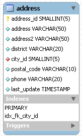
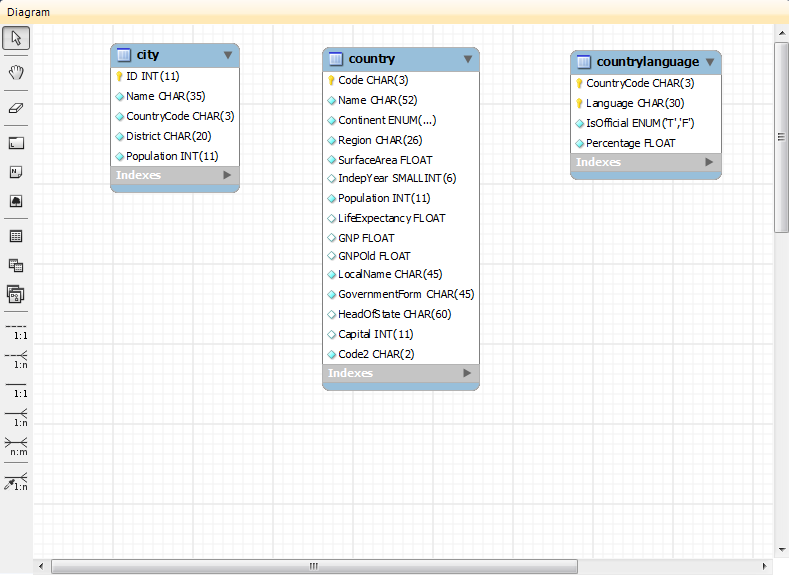
As shown in the preceding diagram the primary key is indicated by a key icon and indexed fields are indicated by a different colored diamond icon. Click the arrow to the right of the table name to toggle the display of the fields. Toggle the display of indexes and triggers in the same way.
Right-clicking a table opens a pop-up menu with the following options:
With the exception of the deletion option, these menu options function as described in Section 7.7.1.1, “Adding Tables to the Physical Schemata”. The behavior of the delete option is determined by your MySQL Workbench options settings. For more information, see Section 5.4.4, “The Model Tab”.
The MySQL Table Editor is a component that enables the creation and modification of tables. Using the MySQL Table Editor you can add or modify a table's columns or indexes, change the engine, add foreign keys, or simply alter the table's name.
The MySQL Table Editor can be accessed from the MySQL Workbench by first
selecting the MySQL Model tab and then double
clicking a table in the Physical Schemata panel.
You can also access it from an EER Diagram by double-clicking a
table object.
Any number of tables may be edited in the MySQL Table Editor at any one time. Adding another table creates a new tab at the top of the editor. By default the MySQL Table Editor appears docked at the bottom of the application.
The MySQL Table Editor is shown in the following figure.
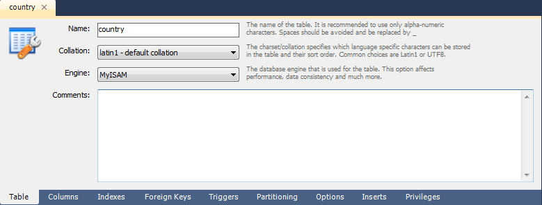
The MySQL Table Editor consists of a work space divided into the following tabs:
Table: Use this table to edit features that apply to the table as a whole
Columns: Use this tab to add or modify columns
Indexes: Use this tab to add or modify indexes
Foreign Keys: Use this tab to add or modify foreign keys
Triggers: Use this tab to add or modify triggers
Partitioning: Use this tab to manage partitioning
Options: Use this tab to add or modify various general, table and row level options
Inserts: Use this tab for writing INSERT statements
Privileges: Use this tab to set privileges on the table
Each of these tabs is discussed in further detail in the following sections.
Use this tab to edit the table name or add a comment to the table. Easily change the collation or the table engine using drop down list boxes.
The Columns tab is used to display and edit all
the column information for a table. Using this tab, you can add,
drop, and alter columns.
You can also use the column tab to change the name, data type, default value, and other properties of your table's columns.
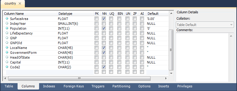
To add a column simply click the Column Name
field in an empty row and enter an appropriate value. Select a
data type from the Datatype drop down list
box. Select a column property checkbox as required according to
the following list of column properties:
PK: Primary key
NN: Not null
UQ: Unique
BIN: Binary
UN: Unsigned
ZF: Zero fill
AI: Autoincrement
Right-clicking a row under the Column Name
column opens a pop-up window with the following options:
: Move the selected column up.
: Move the selected column down.
: Select multiple contiguous columns by right-clicking and pressing the Shift key. Use the Ctrl key to select noncontiguous columns.
: Update all information in the
Columnstab.: Clear the assigned default value.
: Set the column default value to
NULL.: Set the column default value to
".
To change the name, data type, default value, or comment of a column, double-click the value you wish to change. The content then becomes editable.
You can also add column comments to the Column
Comment text area. It is also possible to set the column
collation, using the listbox in the Column
Details panel.
To the left of the column name is an icon that indicates whether
the column is a member of the primary key. If the icon is a small
key, that column belongs to the primary key, otherwise the icon is
a blue diamond or a white diamond. A blue diamond indicates the
column has NN set. To add or remove a column from the primary key,
double-click the icon. You can also add a primary key by checking
the PRIMARY KEY checkbox in the Column
Details section of the table editor.
If you wish to create a composite primary key you can select multiple columns and check the PK checkbox. However, there is an additional step that is required, you will need to click the Indexes tab, then in the Index Columns panel you need to set the desired order of the primary keys.
When entering default values, in the case of
CHAR and VARCHAR data
types MySQL Workbench will attempt to automatically add quotation
marks, if the user does not start their entry with one. For
other data types the user must manage quoting if required, as it
will not be handled automatically by MySQL Workbench.
Care must be taken when entering a default value for non-numeric
ENUM columns. When entering a non-numeric
default value it will not be automatically quoted. You must
manually add single quote characters for the default value. Note
that MySQL Workbench will not
prevent you from entering the default value without the single
quotation marks. If a non-numeric default value is entered
without quotation marks, this will lead to errors. For example,
if the model is reverse engineered, the script will contain
unquoted default values for ENUM columns and
will fail if an attempt is made to run the script on MySQL
Server.
The Indexes tab holds all index information for
your table. You can add, drop, and modify indexes using this tab.
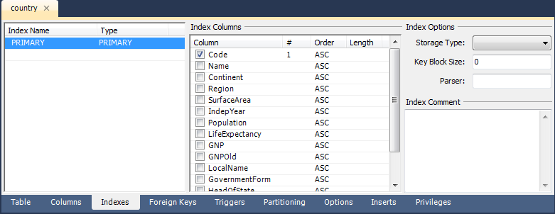
Select an index by right-clicking it. Doing this displays information about the index in the Index Columns section.
To add an index, click the last row in the index list. Enter a name for the index and select the index type from the drop down list box. Select the column or columns that you wish to index by checking the column name in the Index Columns list. You can remove a column from the index by removing the check mark from the appropriate column.
You can also specify the order of an index by choosing
ASC or DESC under the
Order column. Create an index prefix by
specifying a numeric value under the Length
column. You cannot enter a prefix value for fields that have a
data type that does not support prefixing.
To drop an index, right-click the row of the index you wish to delete and then select the menu option.
The Foreign Keys tab is organized in much the
same fashion as the Indexes tab and adding or
editing a foreign key is similar to adding or editing an index.
To add a foreign key, click the last row in the Foreign
Key Name list. Enter a name for the foreign key and
select the column or columns that you wish to index by checking
the column name in the Column list. You can
remove a column from the index by removing the check mark from the
appropriate column.
Under Foreign Key Options choose an action for the update and delete events.
The options are:
RESTRICT
CASCADE
SET NULL
NO ACTION
To drop a foreign key, right-click the row you wish to delete and then select the menu option.
To modify any of the properties of a foreign key, simply select it and make the desired changes.
The Triggers tab opens a text area for editing
an existing trigger or creating a new trigger. Create a trigger as
you would from the command line.
If you wish to enable partitioning for your table check the Enable Partitioning check box. Doing this enables the partitioning options.
The Partition By drop down list box displays the types of partitions you can create. These are:
HASHLINEAR HASHKEYLINEAR KEYRANGELIST
Use the Parameters text box to define the parameter(s) that will be supplied to the partitioning function, an integer column value for example.
Choose the number of partitions from the Partition Count drop down list box. If you wish to manually configure your partitions check the Manual check box. Doing this enables entry of values into the partition configuration table. The entries in this table are:
PartitionValuesData DirectoryIndex DirectoryMin RowsMax RowsComment
Subpartitioning is also available. For more information about partitioning see Partitioning.
The Options tab enables you to set several types of options. These are grouped into the following frames:
General Options
Row Options
Storage Options
Merge Table options
Each of these is discussed in more detail in the following sections.
General Options
In the General Options frame, choose a pack
keys option. The options are Default,
Pack None, and Pack All. You
may also encrypt the definition of a table. The
AUTO_INCREMENT and delayed key update behaviors
apply only to MyISAM tables.
Row Options
To set the row format, choose the desired row format from the
drop-down list. See MyISAM Table Storage Formats for
more information about the different row formats that are
available. This only applies to MyISAM tables.
These options are:
Default
Dynamic
Fixed
Compressed
Redundant
Compact
When you expect a table to be particularly large, use the
Avg. Row, Min. Rows, and
Max. Rows options to enable the MySQL server
to better accommodate your data. See
CREATE TABLE Syntax for more information on how to use
these options.
Storage Options
The Storage Options section is used to
configure a custom path to the table storage and data files. This
option can help improve data integrity and server performance by
locating different tables on different hard drives. This option is
only available for MyISAM tables.
Merge Table Options
The Merge Table Options section is used to
configure MERGE tables in MyISAM. To create a MERGE table, select
MERGE as your storage engine and then specify the tables you wish
to MERGE in the Union Tables dialog.
You can also specify the action the server should take when users
attempt to perform INSERT statements on the merge table. See
The MERGE Storage Engine for more information about
MERGE tables. Again, this only applies to MyISAM tables. You may
also select the Merge Method by selecting from
the drop down list box.
Use the Inserts tab to insert records into the
table.
To edit a record simply click the field you wish to change and enter the new data. Right-clicking a row displays a menu with the following items:
Set Field(s) to NULL:
Delete Row(s):
Copy Row Content: Copies the row to the clipboard. Strings are copied quoted, and NULLs are preserved.
Copy Row Content (unquoted): Copies the row to the clipboard. Strings are not quoted and NULLs are copied as a space.
Copy Field Content: Copies the value of the selected field to the clipboard. Strings are quoted.
Copy Field Content (unquoted): Copies the value of the selected field to the clipboard. Strings are not quoted.
Note that the insert editor features a toolbar. This has the same functionality as explained in Section 6.7.4.5, “Results Tabsheets” and Section 6.7.4.6, “Live Editing Tabsheets”. You can also hover the cursor over the toolbar to display tooltips.
Any records you add will be inserted when you forward engineer the
database (if you choose the Generate INSERT statements
for tables option).
Note when entering string values that there is slightly different behavior between the 5.0, 5.1 and 5.2 versions of MySQL Workbench.
For 5.0 and 5.1 if a string is entered without leading and trailing quotation marks, the Inserts Editor adds quoting and escapes characters that require it. However, if quoted text is entered, the Inserts Editor carries out no further checks since it assumes a correctly escaped and quoted sequence has been entered.
5.2 features a new Inserts Editor. In this case the user enters the string without quoting or escaping and the Inserts Editor takes care of all quoting and escaping as required.
It is possible to enter a function, or other expression, into a
field. If doing so, the prefix \func should
be used, to prevent MySQL Workbench from escaping quotation marks.
For example, if entering the expression
md5('fred') MySQL Workbench would generate the
code md5(\'fred\'). To prevent this enter the
expression as \func md5('fred'). This will
ensure that the quoting is not escaped.
Use the Privileges tab to assign specific roles
and privileges to a table. You may also assign privileges to a
role using the role editor. For a discussion of this topic see
Section 7.5.5.1, “Adding Roles”.
When this tab is first opened, all the roles that have been created are displayed in the list box on the right. Move the roles you wish to associate with this table to the Roles list box on the left. Do this by selecting a role and then clicking the button. Use the Shift key to select multiple contiguous roles and the Ctrl key to select noncontiguous roles.
To assign privileges to a role, click the role in the Roles list box. Doing this displays all available privileges in the Assigned Privileges list box. The privileges that display are:
ALLCREATEDROPGRANT OPTIONREFERENCESALTERDELETEINDEXINSERTSELECTUPDATETRIGGER
You can choose to assign all privileges to a specific user or any
other privilege as listed previously. Privileges irrelevant to a
specific table, the FILE privilege for example,
are not shown.
If a role has already been granted privileges on a specific table, those privileges show as already checked in the Assigned Privileges list box.
Foreign key constraints are supported for the
InnoDB storage engine only. For other storage
engines the foreign key syntax is correctly parsed but not
implemented. For more information see
Foreign Keys.
Using MySQL Workbench you may add a foreign key from within the table editor or by using the relationship tools on the vertical toolbar of an EER Diagram. This section deals with adding a foreign key using the foreign key tools. To add a foreign key using the table editor see Section 7.7.1.3.5, “The Foreign Keys Tab”.
Using the graphical tools to add foreign keys is most effective when you are building tables from the ground up. If you have imported a database using an SQL script and do not need to add fields to your tables you may find it more effective to define foreign keys using the table editor.
There are six foreign key tools on the vertical toolbar on the left side of an EER Diagram. These tools are:
The
one-to-one non-identifying relationshiptoolThe
one-to-many non-identifying relationshiptoolThe
one-to-one identifying relationshiptoolThe
one-to-many identifying relationshiptoolThe
many-to-many identifying relationshiptoolThe
Place a Relationship Using Existing Columnstool
An identifying relationship is one where the child table cannot be uniquely identified without its parent. Typically this occurs where an intermediary table is created to resolve a many-to-many relationship. In such cases, the primary key is usually a composite key made up of the primary keys from the two original tables. An identifying relationship is indicated by a solid line between the tables and a nonidentifying relationship is indicated by a broken line.
Create or drag and drop the tables that you wish to connect. Ensure that there is a primary key in the table that will be on the “one” side of the relationship. Click on the appropriate tool for the type of relationship you wish to create. If you are creating a one-to-many relationship, first click the table that is on the “many” side of the relationship, then on the table containing the referenced key.
Doing this creates a field in the table on the many side of the
relationship. The default name of this field is
table_name_key_name where the table
name and the key name are both derived from the table containing
the referenced key.
When the many-to-many tool is active, double-clicking a table creates an associative table with a many-to-many relationship. For this tool to function there must be a primary key defined in the initial table.
Use the , menu item to set a project-specific default name for the foreign key column (see Section 7.5.1.5.4, “The Relationship Notation Menu Option”). To change the global default see Section 5.4.4, “The Model Tab”.
To edit the properties of a foreign key, double-click anywhere on the connection line that joins the two tables. Doing this opens the relationship editor.
Mousing over a relationship connector highlights the connector and the related keys as shown in the following figure.
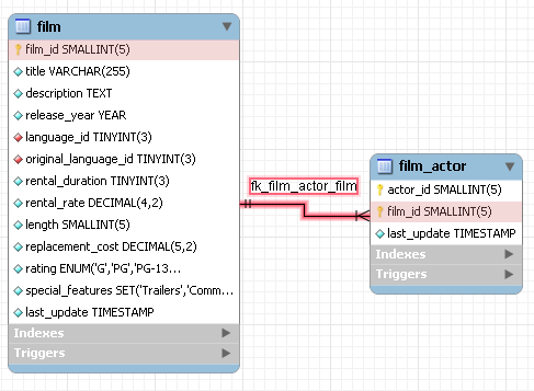
The film and the film_actor
tables are related on the film_id field and
these fields are highlighted in both tables. Since the
film_id field is part of the primary key in the
film_actor table, a solid line is used for the
connector between the two tables.
If the placement of a connection's caption is not suitable, you
can change its position by dragging it to a different location. If
you have set a secondary caption, its position can also be
changed. (For more information about secondary captions see
Section 7.7.2.3, “The Properties of a Connection”. Where the notation
style allows, Classic for instance, the
cardinality indicators can also be repositioned.
The relationship notation style in Figure 7.11, “The Relationship Connector” is the default, crow's foot. If you are using a commercial version of MySQL Workbench you can change this. For more information, see Section 7.5.1.5.4, “The Relationship Notation Menu Option”.
You can select multiple connections by holding down the Ctrl key as you click a connection. This can be useful for highlighting specific relationships on an EER diagram.
Double-clicking a relationship on the EER diagram canvas opens up the relationship editor. This has two tabs: Relationship, and Foreign Key.
The Relationship tab
In the Relationship tab you can set the
caption of a relationship using the Caption
text box. This name displays on the canvas and is also the name
used for the constraint itself. The default value for this name is
fk_.
Use the ,
menu item to set a project-specific default name for foreign keys.
To change the global default see
Section 5.4.4, “The Model Tab”.
source_table_destination_table
You can also add a secondary caption to a relationship and also a comment.
The Visibility Settings frame is used to
determine how the relationship is displayed on the EER Diagram
canvas. Fully Visible is the default but you
can also choose to hide relationship lines or to use split lines.
The split line style is pictured in the following:
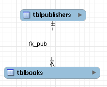
A broken line connector is used to indicate a nonidentifying relationship. The split line style can be used with either an identifying relationship or a nonidentifying relationship. It is used for display purposes only and does not indicate anything about the nature of a relationship.
To set the notation of a relationship go to the , menu item. For more information, see Section 7.5.1.5.4, “The Relationship Notation Menu Option”.
The Foreign Key tab
The Foreign Key tab contains several frames: Referencing Table, Cardinality and Referenced Table.
The Mandatory checkboxes are used to select
whether the referencing table and the referenced table are
mandatory. The default value for both of these constraints is
true, which is indicated by the checkboxes
being checked.
In the Cardinality frame there is a set of radio buttons that allow you to choose whether the relationship is one-to-one or one-to-many. There is also a checkbox that enables you to specify whether the relationship is an identifying relationship.
To select a connection, right-click it. When a connection is selected it is highlighted and its properties are displayed in the properties palette. The properties of a connection are quite different from the properties of other objects. These properties are described in the following list:
caption: The name of the object. By default this property is centered above the connection line. Its default value is the name of the foreign key.captionXOffs: The “x” offset of the caption.captionYOffs: The “y” offset of the caption.comment: The comment associated with the relationship.drawSplit: Whether or not to show the relationship as a continuous line.endCaptionXOffs: The “x” termination point of the caption offset.endCaptionYOffs: The “y” termination point of the caption offset.extraCaption: A secondary caption. The default location for this extra caption is centered beneath the connection line.extraCaptionXOffs: The “x” offset of the secondary caption.extraCaptionYOffs: The “y” offset of the secondary caption.mandatory: Whether or not the entities are mandatory. For more information, see Section 7.7.2.2, “The Relationship Editor”.many: False if the relationship is a one-to-one relationship.middleSegmentOffset: The offset of the middle section of the connector.modelOnly: when this is set the connection will not be propagated to the DDL. It is just a logical connection drawn on a diagram. This is used, for example, when drawing MyISAM tables with a visual relationship, but with no foreign keys.name: The name used to identify the connection on the EER Diagram canvas. Note that this is not the name of the foreign key.referredMandatory: Whether or not the referred entity is mandatorystartCaptionXOffs: The start of the “x” offset of the caption.startCaptionYOffs: The start of the “y” offset of the caption.
In most cases you can change the properties of a relationship
using the relationship editor rather than the
Properties palette.
If you make a relationship invisible by hiding it using the relationship editor's Visibility Settings, and then the relationship editor is closed, you will no longer be able to select the relationship to bring up its relationship editor. To make the relationship visible again you will need to expand the table object relating to the relationship in the Layers palette and select the relationship object. Once selected, you can edit the object by right-clicking, and selecting . You can then set the Visibility Settings to Fully Visible. The relationship will then be visible in the EER Diagram window.
You can add views to a database either from the Physical
Schemata section of the MySQL Model
page or from the EER Diagram.
Double-clicking the Add View icon in the
Physical Schemata section of the MySQL
Model page adds a view with the default name of
view1. If a view with this name already exists,
the new view is named view2.
Adding a new view automatically opens the view editor docked at the bottom of the application. Using the view editor is described in Section 7.7.3.3, “The View Editor”.
Right-clicking a table opens a pop-up menu with the following options:
If the table editor is not open the option opens it. If it is already open, the selected table replaces the previous one. opens a new view editor tab.
The cut and copy options are useful for copying views between
different schemata and
copies the CREATE VIEW statement to the
clipboard.
Use the to remove a view from the database. There will be no confirmation dialog box.
Any views added to the Physical Schemata also
show up in the Catalog palette on the left side
of the application. They may be added to an EER Diagram, when in
EER Diagram view, by dragging and dropping them from this palette.
Views can also be added to an EER Diagram using the
View tool on the vertical toolbar. To do this
make sure that the EER Diagram tab is selected,
and left-click the view icon on the vertical toolbar. The view
icon is the two overlapping rectangles found below the table icon.
Clicking this icon changes the mouse pointer to a view pointer. You can also change the mouse pointer to a view pointer by pressing the V key.
Choosing the View tool changes the contents of
the toolbar that appears immediately below the main menu bar. When
the Views pointer is active, this toolbar
contains a drop down list box of schemata and a drop down color
chart. Use these list boxes to select the appropriate schema and
color accent for the new view. Make sure that you associate the
new view with a database. The color of your view can easily be
changed later using the Properties palette.
Create a view by clicking anywhere on the EER Diagram canvas. This
creates a new view with the default name view1.
To revert to the default mouse pointer, click the arrow icon at
the top of the vertical toolbar.
Right-clicking a view opens a pop-up menu. With the exception of the delete option, these menu options function as described in Section 7.7.3.1, “Adding Views to the Physical Schemata”. The behavior of the delete option is determined by your MySQL Workbench options settings. For more information, see Section 5.4.4, “The Model Tab”.
You can invoke the view editor by double-clicking a view object on
the EER Diagram canvas or by double-clicking a view in the
Physical Schemata section on the MySQL
Model page. Doing this opens the view editor docked at
the bottom of the application. Double-clicking the title bar
undocks the editor. Do the same to redock it. Any number of views
may be open at the same time. Each additional view appears as a
tab at the top of the view editor.
There are three tabs at the bottom of the view editor, the View, Comments, and the Privileges tabs. Navigate between different tabs using the mouse or from the keyboard by pressing Ctrl + Alt + Tab.
The View Tab
From the View tab of the view editor you can
perform the following tasks:
Rename the view using the Name text box.
Enter the SQL to create a view using the SQL text area.
Comment a view using the Comments text area.
The Comments
Tab
This tab enables you to enter comments for a particular view.
The Privileges
Tab
The Privileges tab of the view editor functions
in exactly the same way as the Privileges tab
of the table editor. For more information, see
Section 7.7.1.3.10, “The Privileges Tab”.
When you select a view on the EER Diagram canvas, its properties
are displayed in the Properties palette. Most
of the properties accessible from the
Properties palette apply to the appearance of a
view on the EER Diagram canvas.
For a list of the properties accessible through the
Properties palette see
Section 7.5.11, “The Properties Palette”.
You can add Routine Groups to a database either from the Physical Schemata section of the MySQL Model page or from an EER Diagram. Routines may only be added from the Physical Schemata section of the MySQL Model page.
To view an existing schema, along with its Routines and Routine Groups, select , from the main menu. After the schema has been added to the current model, you can see the schema objects on the Physical Schemata panel on the MySQL Model page. The Routines and Routine Groups are listed there.
MySQL Workbench unifies both stored procedures and stored functions into one logical object called a Routine. Routine Groups are used to group routines that are related. You can decide how many Routine Groups you want to create and you can use the Routine Group Editor to assign specific routines to a group, using a drag and drop interface.
When designing an EER Diagram you can place the Routine Groups on the canvas by dragging them from the Catalog Palette. Placing individual routines on the diagram is not permitted, as it would clutter the canvas.
Double-clicking the Add Routine icon in the
Physical Schemata section of the
MySQL Model page adds a routine with the
default name of routine1. If a routine with
this name already exists, the new routine is named
routine2.
Adding a new routine automatically opens the routine editor docked at the bottom of the application. Using the routine editor is described in Section 7.7.4.1.2, “The Routine Editor”.
Right-clicking a routine opens a pop-up menu with the following options:
The option opens the routine editor.
The cut and paste options are useful for copying routines between different schemata.
Deleting the code for routine from the Routines tab of the Routine Group Editor will result in removal of the routine object from the model.
To remove a routine from a routine group use the controls on the Routine Group tab of the Routine Group Editor.
The action of the delete option varies depending upon the way you have configured MySQL Workbench. For more information, see Section 5.4.4, “The Model Tab”.
You can invoke the routine editor by double-clicking a routine
in the Physical Schemata section on the
MySQL Model page. Doing this opens the
routine editor docked at the bottom of the application. Any
number of routines may be open at the same time. Each additional
routine appears as a tab at the top of the routine editor.
There are two tabs at the bottom of the routine editor, the Routine and the Privileges tabs. Navigate between different tabs using the mouse or from the keyboard by pressing Ctrl + Alt + Tab.
From the Routine tab of the routine editor
you can perform the following tasks:
Rename the routine using the Name text box.
Enter the SQL to create a routine using the SQL text area.
The Privileges tab of the routine editor
functions in exactly the same way as the
Privileges tab of the table editor. For
more information, see
Section 7.7.1.3.10, “The Privileges Tab”.
Privileges are only available in the Standard Edition of MySQL Workbench.
Double-clicking the Add Routine Group icon in
the Physical Schemata section of the
MySQL Model page adds a routine with the
default name of routines1. If a routine group
with this name already exists, the new routine group is named
routines2.
Adding a new routine group automatically opens the routine groups editor docked at the bottom of the application. Using the routine groups editor is described in Section 7.7.4.2.3, “The Routine Group Editor”.
Right-clicking a routine group opens a pop-up menu with the following options:
The option opens the routine group editor. Using the routine group editor is described in Section 7.7.4.2.3, “The Routine Group Editor”.
The cut and paste options are useful for copying routine groups between different schemata.
Deleting a routine group from the MySQL Model
page removes the group but does not remove any routines
contained in that group.
Any routine groups added to the Physical
Schemata also show up in the
Catalog palette on the right side of the
application. They may be added to an EER Digram by dragging and
dropping them from this palette.
Routine groups can also be added to an EER Diagram using the
Routine Groups tool on the vertical toolbar.
To do this make sure that the EER Diagram tab
is selected, and right-click the routine groups icon on the
vertical toolbar. The routine groups icon is immediately above
the lowest toolbar separator.
Clicking the mouse on this icon changes the mouse pointer to a routine group pointer. You can also change the mouse pointer to a routine pointer by pressing the G key.
Choosing the Routine Group tool changes the
contents of the toolbar that appears immediately below the menu
bar. When the Routine Groups pointer is
active, this toolbar contains a drop down list box of schemata
and a drop down color chart. Use these list boxes to select the
appropriate schema and color accent for the new routine group.
Make sure that you associate the new routine group with a
database. The color of your routine group can easily be changed
later using the Properties palette.
Create a routine group by clicking anywhere on the EER Diagram
canvas. This creates a new routine group with the default name
routines1. To revert to the default mouse
pointer, click the arrow icon at the top of the vertical
toolbar.
Right-clicking a routine group opens a pop-up menu. With the exception of the delete option and rename options these menu options function as described in Section 7.7.4.2.1, “Adding Routine Groups to the Physical Schemata”. There is no rename option and the behavior of the delete option is determined by your MySQL Workbench options settings. For more information, see Section 5.4.4, “The Model Tab”.
You can invoke the routine group editor by double-clicking a
routine group object on the EER Diagram canvas or by double
clicking a routine group in the Physical
Schemata section on the MySQL Model
page. Doing this opens the routine group editor docked at the
bottom of the application. Double-clicking the title bar undocks
the editor. Do the same to redock it. Any number of routine
groups may be open at the same time. Each additional routine
group appears as a tab at the top of the routine editor,
There are two tabs at the bottom of the routine editor, the Routine group and the Privileges tabs. Navigate between different tabs using the mouse or from the keyboard by pressing Ctrl + Alt + Tab.
From the Routine Groups tab of the routine
groups editor you can perform the following tasks:
Rename the routine group using the Name text box.
Add routines to the group by dragging and dropping them.
Add comments to the routine group.
The Privileges tab of the routine group
editor functions in exactly the same way as the
Privileges tab of the table editor. For
more information, see
Section 7.7.1.3.10, “The Privileges Tab”.
Privileges are only available in the Standard Edition of MySQL Workbench.
When you select a routine group on the EER Diagram canvas, its
properties are displayed in the Properties
palette. All of the properties accessible from the
Properties palette apply to the appearance
of a routine group on the EER Diagram canvas.
For a list of the properties accessible through the
Properties palette see
Section 7.5.11, “The Properties Palette”.
You can add layers to a database only from an EER Diagram. Layers are used to help organize objects on the canvas. Typically, related objects are added to the same layer; for example, you may choose to add all your views to one layer.
Layers are added to an EER Diagram using the
Layer tool on the vertical toolbar. To do this
select an EER Diagram tab and right-click the
layer icon on the vertical toolbar. The layer icon is the
rectangle with an ‘L’ in the lower
left corner and it is found below the eraser icon.
Clicking the mouse on this icon changes the mouse pointer to a layer pointer. You can also change the mouse pointer to a layer pointer by pressing the L key.
Choosing the Layer tool changes the contents of
the toolbar that appears immediately below the menu bar. When the
Layers pointer is active, this toolbar contains
a drop down color chart. Use this list box to select the color
accent for the new layer. The color of your layer can easily be
changed later using the Properties palette.
Create a layer by clicking anywhere on the EER Diagram canvas and,
holding the left mouse button down, draw a rectangle of a suitable
size. This creates a new layer with the default name
layer1. To revert to the default mouse pointer,
click the arrow icon at the top of the vertical toolbar.
Find below an image of a layer containing a number of views:
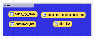
Use the name property of the
Properties palette to change the name of a
layer.
Right-clicking a layer opens a pop-up menu with the following options:
The cut and copy options are useful for copying layers between different schemata.
Since layers are not schema objects, no confirmation dialog box opens when you delete a layer regardless of how you have configured MySQL Workbench. Deleting a layer does not delete schema objects from the catalog.
Add an object to a layer by dragging and dropping it directly
from the Catalog palette onto a layer. If you
pick up an object from an EER diagram you need to press
Ctrl as you drag it on to the layer, otherwise
it will not be "locked" inside the layer.
Locking objects to a layer prevents their accidental removal. You cannot remove them simply by clicking and dragging; in order to remove an object, you also need to press the Ctrl key while dragging it.
As a visual cue that the object is being "locked", the outline of the layer is highlighted as the object is dragged over it.
If you drag a layer over a table object, the table object will automatically be added to the layer. This also works for multiple table objects.
Note that layers cannot be nested, that is, a layer cannot contain another layer object.
When you select a layer on the EER Diagram canvas, its properties
are displayed in the Properties palette. The
properties accessible from the Properties
palette apply to the appearance of a layer on the EER Diagram
canvas.
In some circumstances you may want to make a layer invisible. To
do this, select the layer and, in the
Properties palette, set the
visible property to False.
To locate an invisible object, open the Layers
palette and select the object by double-clicking it. Once an
object is selected you can reset the visible
property from the Properties palette.
For a list of the properties accessible through the
Properties palette see
Section 7.5.11, “The Properties Palette”. In addition to the
properties listed there, a layer also has a
description property. Use this property to
document the purpose of the layer.
You can add notes to a database only from the Model
Notes section of the MySQL Model page.
Notes are typically used to help document the design process.
Double-clicking the Add Note icon in the
Model Notes section of the MySQL
Model page adds a note with the default name of
note1. If a note with this name already exists,
the new note is named note2.
Adding a new note automatically opens the note editor docked at the bottom of the application. Using the note editor is described in Section 7.7.6.2, “The Note Editor”.
Right-clicking a note opens a pop-up menu with the following options:
The option opens the note editor. Using the note editor is described in Section 7.7.6.2, “The Note Editor”.
The cut and copy options are useful for copying notes between different schemata.
Notes can only be added on the MySQL Model
page.
You can invoke the note editor by double-clicking a note object in
the Model Note section on the MySQL
Model page. Doing this opens the note editor docked at
the bottom of the application. Double-clicking the note tab
undocks the editor. Double-click the title bar to redock it. Any
number of notes may be open at the same time. Each additional note
appears as a tab at the top of the note editor.
Using the editor you can change the name of a note or its contents.
Text objects are applicable to an EER diagram only. They can be used for documentation purposes, for example, to explain a grouping of schema objects. They are also useful for creating titles for an EER diagram should you decide to export a diagram as a PDF or PNG file.
Text objects can be added to an EER Diagram using the
Text Object tool on the vertical toolbar. To do
this make sure that the EER Diagram tab is
selected, and right-click the text object icon on the vertical
toolbar. The text object icon is the rectangular icon found below
the label icon.
Clicking the mouse on this icon changes the mouse pointer to a text object pointer. You can also change the mouse pointer to a text object pointer by pressing the N key.
Choosing the Text Object tool changes the
contents of the toolbar that appears immediately below the menu
bar. When the Text Object pointer is active,
this toolbar contains a drop down color chart. Use this list box
to select the color accent for the new text object. The color of
your text object can easily be changed later using the
Properties palette.
Create a text object by clicking anywhere on the EER Diagram
canvas. This creates a new text object with the default name
text1. To revert to the default mouse pointer,
click the arrow icon at the top of the vertical toolbar.
Right-clicking a text object opens a pop-up menu. These menu options are identical to the options for other objects. However, since a text object is not a database object, there is no confirmation dialog box when you delete a text object.
You can invoke the text object editor by double-clicking a text object on the EER Diagram canvas. Doing this opens the editor docked at the bottom of the application. Double-clicking the text object table undocks the editor. Double-click the title bar to redock it. Any number of text objects may be open at the same time. Each additional text objects appears as a tab at the top of the text editor.
Using the editor you can change the name of a text object or its contents.
When you select a text object on the EER Diagram canvas, its
properties are displayed in the Properties
palette. Most of the properties accessible from the
Properties palette apply to the appearance of
a view on the EER Diagram canvas.
For a list of the properties accessible through the
Properties palette see
Section 7.5.11, “The Properties Palette”.
There is no property in the Properties
palette for changing the font used by a text object. To change
the font used by a text object choose the
Appearance tab of the Workbench Preferences
dialog. For more information, see
Section 5.4.7, “The Appearance Tab”.
Images only exist on the EER Diagram canvas; you can only add them from the EER Diagram window.
Images can be added to an EER Diagram using the
Image tool on the vertical toolbar. To add an
image make sure that the EER Diagram tab is
selected, and right-click the image icon on the vertical toolbar.
The image icon is the icon just above the table icon.
Clicking the mouse on this icon changes the mouse pointer to an image pointer. You can also change the mouse pointer to an image pointer by pressing the I key.
Create a image by clicking anywhere on the EER Diagram canvas. This opens a file open dialog box. Select the desired image, and close the dialog box to create an image on the canvas. To revert to the default mouse pointer, click the arrow icon at the top of the vertical toolbar.
Right-clicking this object opens a pop-up menu with the following options:
These menu options function in exactly the same way as they do for other objects on an EER diagram. However, images are not database objects so there is no confirmation dialog box when they are deleted.
You can invoke the image editor by double-clicking a image object on an EER Diagram canvas. Doing this opens the image editor docked at the bottom of the application. Double-clicking the image editor tab undocks the editor. Double-click the title bar to redock it. Any number of images may be open at the same time. Each additional image appears as a tab at the top of the image editor,
Using MySQL Workbench you can reverse engineer a database using a MySQL create script or you can connect to a live MySQL server and import a single database or a number of databases. Reverse engineering using a MySQL DDL script applies to all versions of MySQL Workbench; reverse engineering a database directly from a MySQL server applies to commercial versions of MySQL Workbench only.
Reverse engineering using a create script is done by using the
, ,
menu
options. Doing this opens a file open dialog box with the default
file type set to an SQL script file, a file with the extension
sql.
You can create a data definition (DDL) script by executing the
mysqldump command.
Using the db_name
--no-data >
script_file.sql--no-data option ensures that the
script contains DDL statements only. However, if you are working
with a script that also contains DML statements you need not
remove them; they will be ignored.
If you plan to redesign a database within MySQL Workbench and then
export the changes, be sure to retain a copy of the original DDL
script. You will need the original script to create an
ALTER script. For more information, see
Section 7.7.10.1.2, “Altering a Schema”.
Use the --databases option with
mysqldump if you wish to create the database as
well as all its objects. If there is no CREATE DATABASE
statement in your
script file, you must import the database objects into an existing
schema or, if there is no schema, a new unnamed schema is created.
db_name
If your script creates a database, a new physical schemata tab is
created on the MySQL Model page.
Any database objects may be imported from a script file in this fashion; tables, views, routines, and routine groups. Any indexes, keys, and constraints are also imported. Objects imported using an SQL script can be manipulated within MySQL Workbench in the same way that any other objects can.
Before exiting, be sure to save the schema. Choose the
, menu item and the
reverse-engineered database will be saved as a MySQL Workbench
file with the extension mwb.
See Section 7.8.1, “Importing a Data Definition SQL Script” for a tutorial on
reverse engineering the sakila database.
This section explains how to reverse engineer a live database using MySQL Workbench.
Select the , menu item from the main menu. Doing this opens the Reverse Engineer Database wizard.
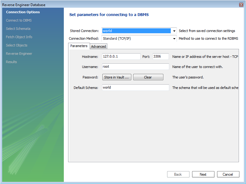
The first page of the wizard enables you to set up a connection to the live database you wish to reverse engineer. This enables you to set up a new connection, or select a previously created connection. Typical information required for the connection includes hostname, username and password.
Once this information has been entered, or you have selected a stored connection, click the button to proceed to the next page:
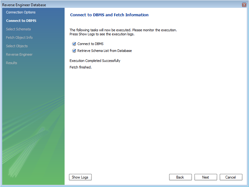
Review the displayed information to make sure that the connection did not generate errors, then click .
On the next page you can select the database schema you want to connect to among those available on the server. Simply click the checkbox or checkboxes associated with the schema you wish to process:
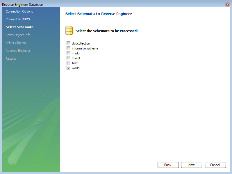
Once you have selected the desired schema, click the button to continue.
The wizard then displays the tasks it carried out and summarizes the results of the operation:
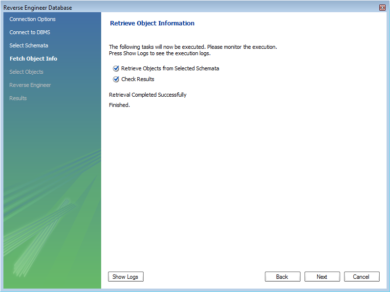
Review the results before clicking to continue.
The next page is the Select Objects page. It is
sectioned off by object type. This screen is of special interest
if you do not wish to import all the objects from the existing
database—this screen gives you the option of filtering which
objects are imported. Each section has a button. Click this button if you do not want to
import all the objects of a specific type.
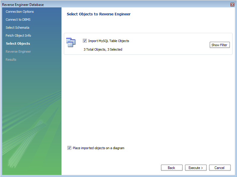
For the Import MySQL Table Objects section, if you click the button the following page is displayed:
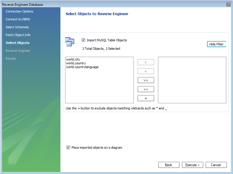
This enables you to select specific tables that you wish to import. Having selected the desired tables you can optionally hide the filter by clicking the button.
The other sections, such as MySQL Routine Objects, have similar filters available.
You can click to continue to the next page.
The wizard then displays the tasks that have been carried out and whether the operation was successful or not. If errors were generated then you can click the button to see the nature of the errors.
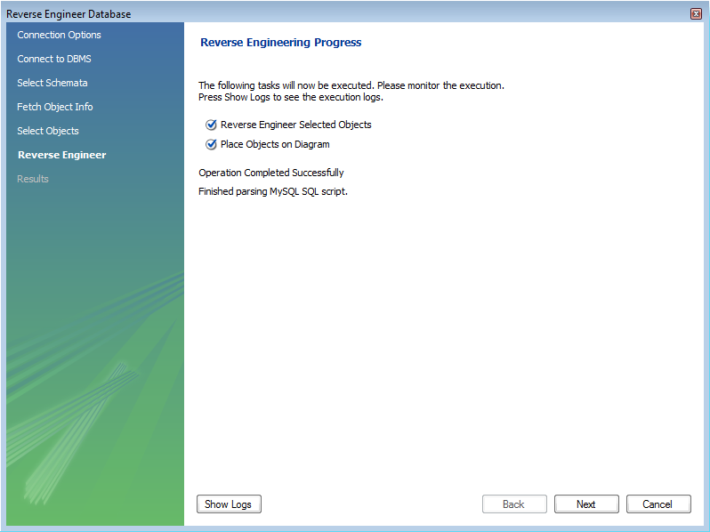
Click to continue to the next page.
The final screen of the wizard provides a summary of the reverse engineered objects:
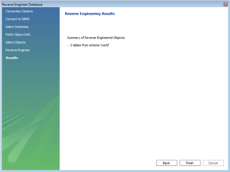
Click to exit the wizard.
Before exiting MySQL Workbench be sure to save the schema. Choose the
, menu item and the
reverse-engineered database will be saved as a MySQL Workbench
file with the extension mwb.
During reverse engineering the application checks for tables and views that duplicate existing names and disallows duplicate names if necessary. If you attempt to import an object that duplicates the name of an existing object you will be notified with an error message. To see any errors that have occurred during reverse engineering you can click the button . This will create a panel containing a list of messages, including any error messages than may have been generated. Click the button to close the panel.
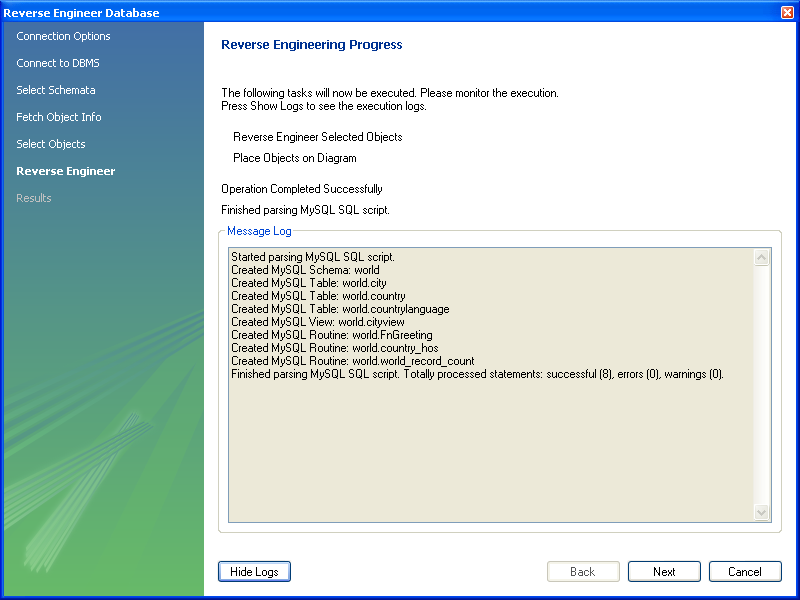
If you wish to import an object with the same name as an existing object, rename the existing object before reverse engineering.
If you import objects from more than one schema, there will be a
tab in the Physical Schemata section of the
MySQL Model page for each schema imported.
You cannot reverse engineer a live database that has the same name as an existing schema. If you wish to do this, first rename the existing schema.
It is possible to forward engineer a database using an SQL script or by connecting to a live database.
To create a script of your database model use the
option found under the
menu. You may export a script to alter an
existing database or create a new database. The script to create a
database is similar to the one created using the
mysqldump db_name
command.
If you choose to create a database, there are a number of export options that you may choose from.
Selecting , , will start the Forward Engineer SQL Script wizard. The first page of the wizard is:
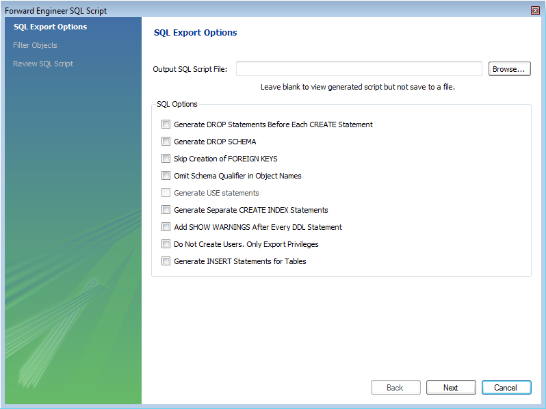
The SQL Export Options displays the following facilities:
Output SQL Script File
You can enter the name of your output file by entering it into the Output SQL Script File text box, or by using the button to select a file. If this text box is left blank you will be able to view the generated script, but it will not be saved to a file.
Generate DROP Statements Before Each CREATE Statement
Omit Schema Qualifier in Object Names
Generate Separate CREATE INDEX Statements
Choosing this option creates separate statements for index
creation instead of creating indexes as part of a
CREATE TABLE statement.
Add SHOW WARNINGS after every DDL statement
Do Not Create Users. Only Export Privileges
To update the privileges of existing users as opposed to
creating new users, select this check box. Exporting privileges
for nonexistent users will result in errors when you execute the
CREATE script. Exporting users that already
exist, will also result in an error.
Generate INSERT Statements for Tables
If you have added any records to a table using the Insert tab of the MySQL Table Editor, choose this option. For more information about inserting records see Section 7.7.1.3.9, “The Inserts Tab”.
Clicking takes you to the SQL Object Export Filter page where you can select the objects you wish to export.
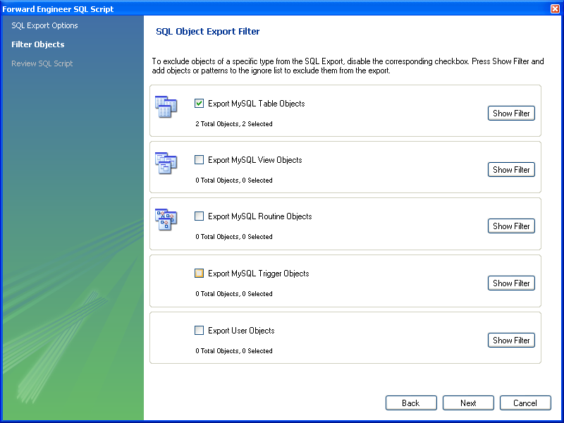
Precise control over the objects to be exported can be fine tuned by clicking the button. Once the objects to be exported have been selected it is possible to reduce the expanded panel by clicking the same button, now labelled .
Having selected the objects you wish to export you can click the button to review the script that has been generated:
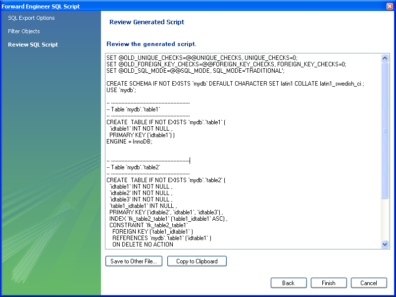
The button saves the script file and exits. You may return to the previous screen using the button.
You can then use the saved script to create a database.
The menu option for altering a schema, , is used for updating a database that has been redesigned within MySQL Workbench. Typically, this option is used when the SQL script of a database has been imported into MySQL Workbench and changed, and then you want to create a script that can be run against a database to alter it to reflect the adjusted model. For instructions on importing a DDL script see Section 7.7.9.1, “Reverse Engineering Using a Create Script”.
Select , , to start the Foward Engineer an ALTER Script wizard. You will be presented with the first page:
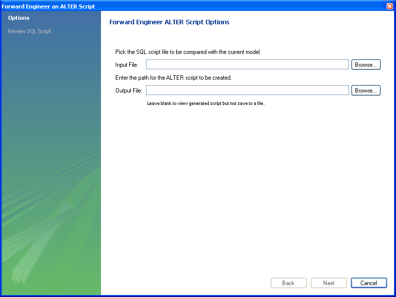
This first screen enables you to select a SQL script and compare it with the model currently in MySQL Workbench. The difference between the two models will be used to create an alter script that can be used to modify the target schema so that it matches the model held in MySQL Workbench. You can also simply view the script generated, rather than saving it to a file, by leaving the Output File text box empty.
The script selected as the Input File must use full schema
qualifiers, such as schema_name.table_name,
otherwise MySQL Workbench will not be able to generate a useable
alter script.
Pressing brings you to the Review SQL Script screen.
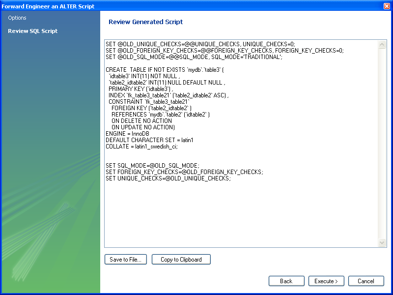
Here you can review and change the alter script that will be
generated. Make any changes you wish and, if you are happy with
the changes, save the ALTER script to file
using the button. You
can also click the button to
write the script to the previously specified output file.
The generated script can then be used to update the database.
Use forward engineering to export your schema design to a MySQL server.
Select the schema that you wish to forward engineer and then choose , option from the main menu.
The first page to be displayed is Catalog Validation (validation is only available in the Standard Edition):
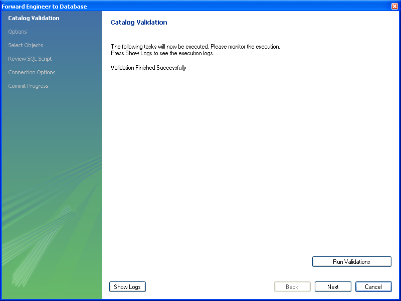
Click to validate the catalog.
Click the to continue.
The next page enables you to set options for the database to be created. These options are as described in Section 7.7.10.1.1, “Creating a Schema”:
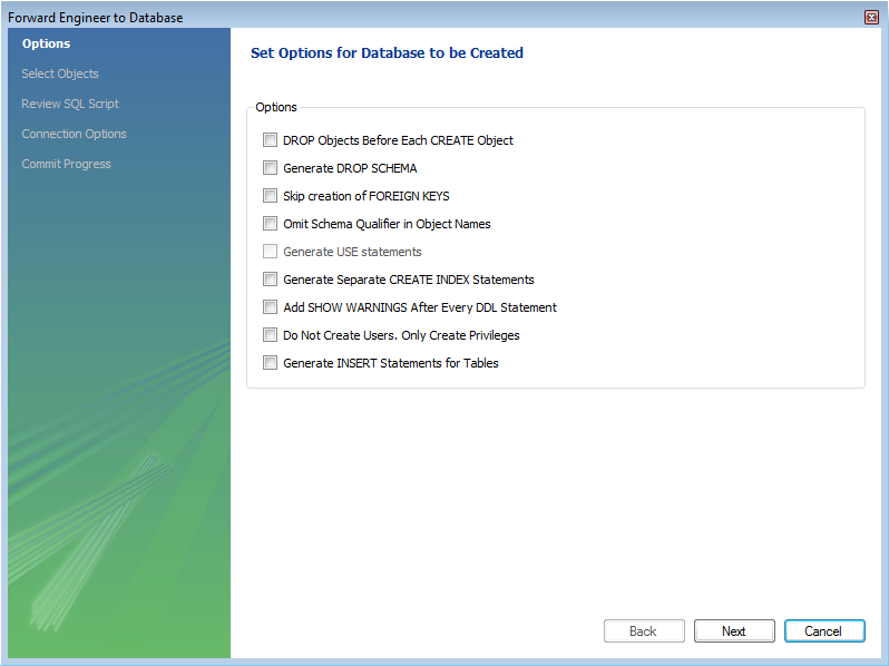
Select the required options and then click .
The next page enables you to select the objects to forward engineer:
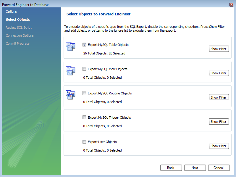
To select a subset of objects to forward engineer use the / button, and then select specific objects. Once you have selected your objects click to continue
On the Review Script page you may review and
edit the SQL script that will be executed:
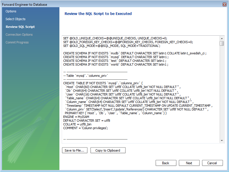
Click to continue if you are satisfied with the generated script.
The next step of the process is to connect to a MySQL server in order to create the new database schema. This page enables you to use a previously stored connection, or enter the connection parameters:
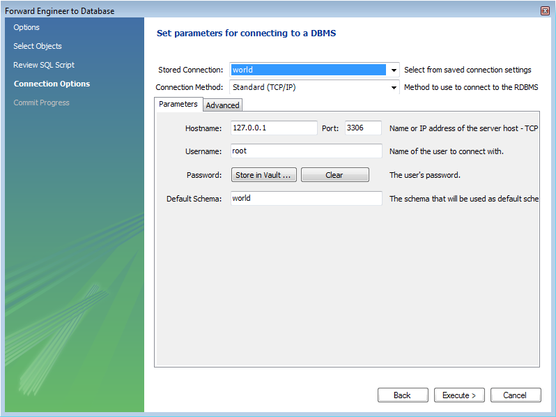
Once the connection parameters have been set click . The next page of the wizard displays the results of the forward engineering process:
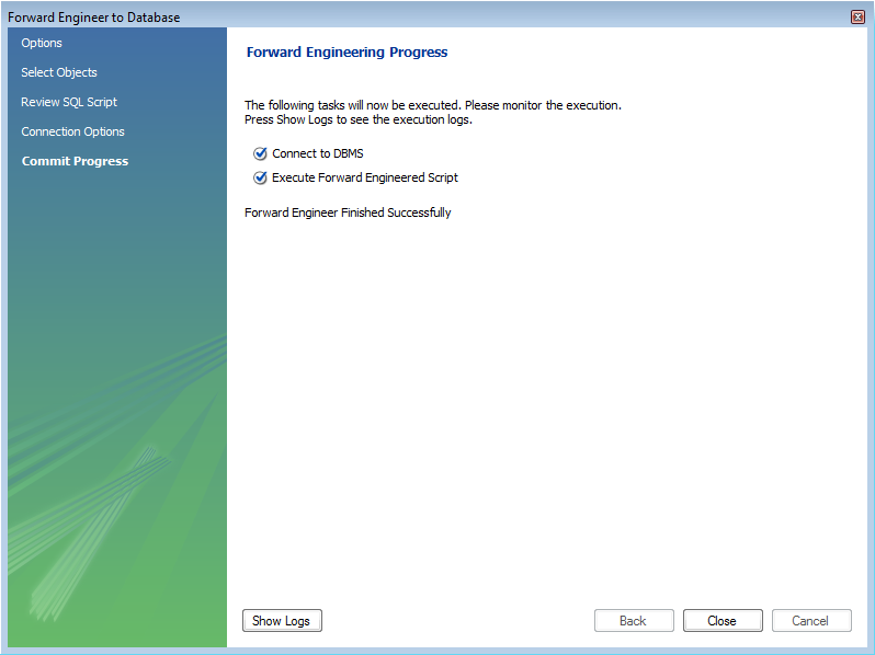
You can confirm the creation of the schema by connecting to the
target MySQL server and issuing the SHOW
DATABASES; command.
It is possible to synchronize a model in MySQL Workbench with a live database. By default, the synchronization process will change the live database to be the same as the model, but this is configurable during the synchronization process.
MySQL Workbench enables control over the direction of synchronization, and the objects synchronized, in a completely flexible way. You can choose to synchronize only certain tables, allow synchronization to the live database only, allow synchronization from the live database to the model only, or a combination of directions. In effect you have complete control as to whether the synchronization is unidirectional or bidirectional, and which objects exactly are subject to synchronization. This is all controlled in the Select Changes to Apply page of the synchronization wizard:
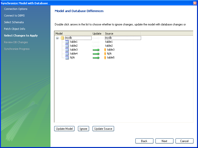
In the above example the live database consists of
table1, table2 and
table3. In MySQL Workbench an additional table,
table4, has been created, along with a
relationship between it and table3. Further,
table5 exists in the live database, but not in
the model. The actions that are configured to occur would result
in table3 being altered (to include the
relationship with table4),
table4 being created and
table5 being dropped, in the live database. It
is possible to reconfigure this though.
The next example shows how the direction of synchronization can be changed:
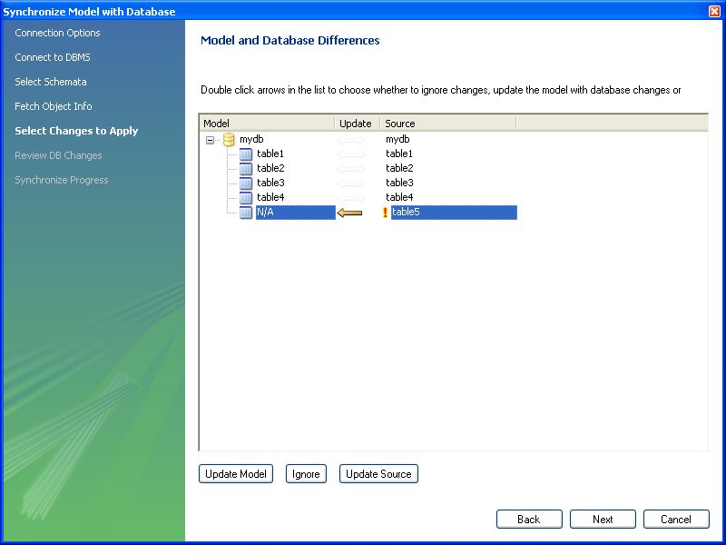
In this case the synchronization direction has been changed so
that rather than the default action of table5
being dropped from the live database, it will be incorporated into
the MySQL Workbench model.
For convenience the wizard provides three additional buttons to allows synchronization directions to be applied to a group of selected changes. The button causes the selected changes to only be applied to the model itself:

In the above example table7 would be added to
the model.
The button causes the selected changes to be ignored, no synchronization will take place for those changes:
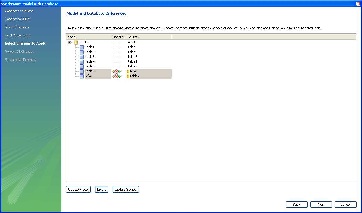
In the above example no changes would take place.
The button causes the selected changes to only update the live database:
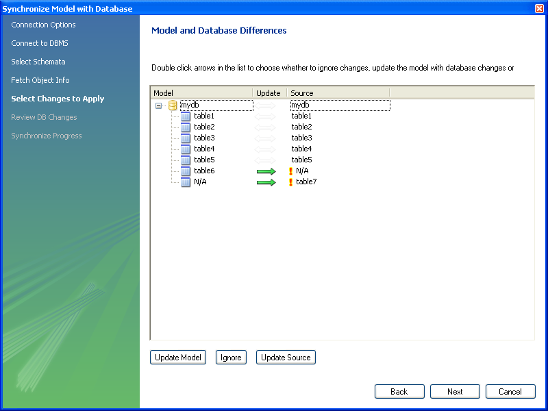
In this example table6 would be added to the
live database and table7 would be dropped from
the live database.
It is also possible to control individual changes by clicking the arrows. Clicking an arrow causes it to change between the three available synchronization directions:
In the above example table6 will be created in
the live database, and table7 will be created
in the model.
This facility enables you to create a report detailing the differences between your MySQL Workbench model, and a live database or script. Select , from the main menu to run the Compare and Report Differences in Catalogs wizard.
Having started the wizard the first step is to specify the catalogs you wish to compare. For example, you may simply wish to compare your live database against your current MySQL Workbench model:
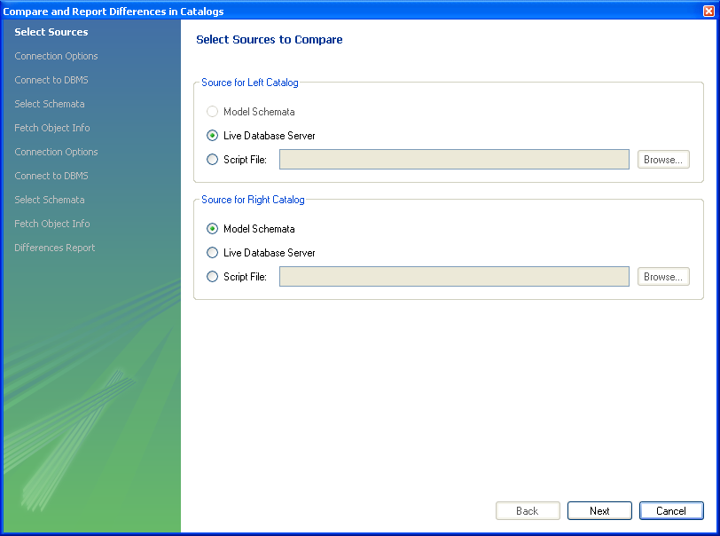
You then proceed through the wizard, providing connection information if accessing a live database. The wizard will then produce a catalog diff report showing the differences between the compared catalogs:
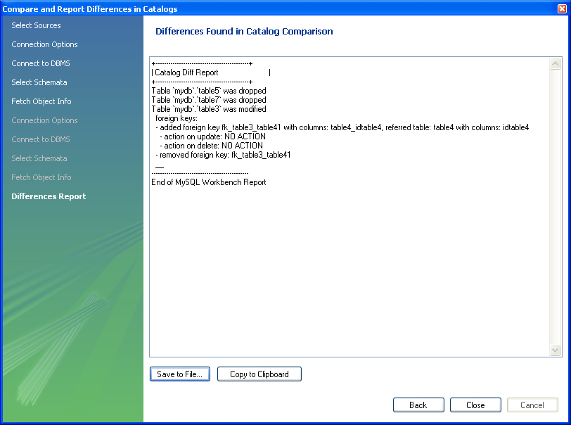
This chapter contains three short tutorials intended to familiarize you with the basics of MySQL Workbench. These tutorials show how MySQL Workbench can be used both to design and to document databases.
Creating a database from scratch is the focus of Section 7.8.2, “Using the Default Schema” and exploring the graphic design capabilities of MySQL Workbench is touched upon in Section 7.8.3, “Basic Modeling”. Both these tutorials show the database design capabilities of MySQL Workbench
Importing an SQL data definition script is probably the quickest way
to familiarize yourself with MySQL Workbench—this tutorial makes
use of the sakila database and emphasizes the use
of MySQL Workbench as a documentation tool. Examples taken from the
sakila database are used throughout the documentation so doing this
tutorial can be very helpful in understanding MySQL Workbench.
For this tutorial use the sakila database
script found in the Example Databases section
of the http://dev.mysql.com/doc/ page.
After downloading the file, extract it to a convenient location.
Open MySQL Workbench and find the menu option by first selecting
and then . Find
and import the sakila-schema.sql file. This
is the script that contains the data definition statements for the
sakila database. The file filter for the file
open dialog window defaults to *.sql so you
should only be able to view files with the sql
extension.
If the file was successfully imported, the application's status
bar reads, Import MySQL Create Script done. To
view the newly imported script, expand the Physical
Schemata section by double-clicking the arrow on the
left of the Physical Schemata title bar. Select
the tab labelled sakila.
Yo may also wish to remove the default schema tab,
mydb. Do this by selecting this tab and then
clicking the button on the upper right in
the Physical Schemata panel.
To view all the objects in the sakila schema,
you may need to expand the Physical Schemata
window. To do this move the mouse pointer anywhere over the gray
area that defines the lower edge of the Physical
Schemata window. Hold down the right mouse button and
move the mouse to adjust the size of the window.
Once you've expanded the window, all the objects in the
sakila database should be visible. Tables
appear at the top followed by views and then routines. There are
no routine groups in this schema, but you should see the
Routine Groups section and an Add
Group icon.
For a complete description of importing a MySQL create script see Section 7.7.9.1, “Reverse Engineering Using a Create Script”.
To create an EER diagram for the sakila
database, first add an EER diagram by double-clicking the
Add Diagram icon in the EER
Diagrams panel. This should create and open a new
EER Diagram.
The EER Diagram canvas is where object
modeling takes place. To add a table to the canvas, select the
Catalog tab in the middle panel on the
right side of the application. This should display any schemata
that appear in the MySQL Model tab.
Find the sakila schema and expand the view of its objects by clicking the button to the left of the schema name. Expand the tables list in the same way.
You can add tables to the EER canvas by picking them up from the
Catalog panel and placing them on the
canvas. Drop the address table and the
city table onto the canvas.
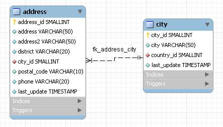
MySQL Workbench automatically discovers that
address.city_id has been defined as a foreign
key referencing the city.city_id field. Drop
the country table onto the canvas and
immediately you should see the relationship between the
country table and the city
table. ( See Figure 7.45, “The sakila EER Diagram” to view a PNG
file of all the relationships in the sakila
database.)
Choose the Properties tab of the panel on the
lower right and then click one of the tables on the canvas. This
displays the properties of the table in the
Properties window. While a table is selected
you can use the Properties window to change a
table's properties. For example, entering
#FF0000 for the color value will change the
color accent to red.
Changing the color of a table is a good way to identify a table
quickly—something that becomes more important as the
number of tables increases. Changing the color of a table is
also an easy way to identify a table in the Model
Navigator panel. This panel, the uppermost panel on
the left side of the screen, gives a bird's eye view of the
entire EER canvas.
Save your changes to a MySQL Workbench Models
file (mwb) by choosing from the
menu or by using the keyboard command
Ctrl S.
When you first open MySQL Workbench a default schema,
mydb appears as the left-most tab of the
Physical Schemata section of MySQL Workbench. You
can begin designing a database by using this default schema.
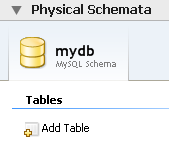
To change the name of the default schema, double-click the schema tab. This opens a schema editor window docked at the bottom of the application. To undock or redock this window, simply double-click anywhere in the editor title bar.
To rename the schema, use the text box labeled Name. Once you have renamed the schema a lightning bolt icon appears right aligned in the Name text box, indicating that other changes are pending. Click the Comments text area and a dialog box opens asking if you wish to rename all schema occurrences. Clicking ensures that your changes are propagated throughout the application. Add comments to the database and change the collation if you wish. Close the schema editor by clicking the button.
Create a new table by double-clicking the Add
Table icon in the Physical
Schemata panel. Doing this opens the table editor
docked at the bottom of the application. If you wish, you can
undock or dock this editor in exactly the same way as the schema
editor window.
Use the first tab of the table editor to change the name, collation, and engine. You may also add a comment.
Add columns to the new table by selecting the Columns tab. Use the default column name or enter a new name of your choosing. Use the Tab key to move to the next column and set the column's data type.
Altering the table by adding indexes or other features is also easily done using the table editor.
Additional objects such as views or routines can be added in the same way as tables.
Any objects you have created can be found in the Catalog palette on the right. To view these schema objects select the Catalog tab in the middle palette on the right. View all the objects by clicking the button to the left of the schema name.
Save your changes to a MySQL Workbench Models
file (mwb) by choosing from the
menu or by using the keyboard command
Ctrl S.
On the MySQL Model page, double-click the
Add
    Diagram
icon. This creates and opens a
new EER Diagram.
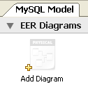
From an EER diagram page you can graphically design a database.
The tools in the vertical toolbar on the left of the
EER Diagram tab are used for designing an
EER diagram. Start by creating a table using the table tool. The
table tool is the rectangular grid in the middle of the vertical
toolbar. Mousing over it shows the message, Place a New
Table (T).
Clicking this tool changes the mouse pointer to a hand with a
rectangular grid. Create a table on the canvas by clicking
anywhere on the EER Diagram grid.
Right-click the table and choose from the pop-up menu. This opens the table editor, docked at the bottom of the application.
The table name defaults to table1. Change the
name by entering invoice into the
Name: text box. Notice that the name of the
tab in the table editor and the name of the table on the canvas,
both change to this new value.
Pressing Tab or Enter while
the cursor is in the table name text box, selects the
Columns tab of the table editor and creates
a default column named, idinvoice.
Pressing Tab or Enter again
sets the focus on the Datatype drop-down list
box with INT selected. Notice that a field
has been added to the table on the EER canvas.
Pressing Tab yet again and the focus shifts to
adding a second column. Add a Description and
a Customer_id column. When you are finished,
close the table editor, by clicking the
button on the top left of the table editor.
Select the table tool again and place another table on the
canvas. Name this table invoice_item. Next
click the 1:n Non-Identifying Relationship
tool.
First click the invoice_item table; notice
that a red border indicates that this table is selected. Next
click the invoice table. Doing this creates a
foreign key in the invoice_item table, the
table on the “many” side of the relationship. This
relationship between the two tables is shown graphically in
crow's foot notation.
Revert to the default mouse pointer by clicking the arrow at the
top of the vertical toolbar. Click on the
invoice_item table and select the
Foreign keys tab.
Click the Foreign key Name text box. The referenced table should show in the Referenced Table column and the appropriate column in the Referenced Column column.
To delete the relationship between two tables, click the line joining the tables and then press Ctrl Delete.
Experiment with the other tools on the vertical toolbar. Delete a relationship by selecting the eraser tool and clicking the line joining two tables. Create a view, add a text object, or add a layer.
Save your changes to a MySQL Workbench Models
file (MWB) by choosing from the
menu or by using the keyboard command
Ctrl S.
This chapter highlights the capabilities of MySQL Workbench as a
documentation tool using the sakila database as
an example. This is a sample database provided by MySQL and found in
the Example Databases section of the
http://dev.mysql.com/doc/ page. An EER diagram is an invaluable
aid to a quick understanding of any database. There is no need to
read through table definition statements; glancing at an EER diagram
can immediately indicate that various tables are related.
You can also see how tables are related; what the foreign keys are and what the nature of the relationship is.
Find below an EER digram showing all the tables in the
sakila database. This image was created using
the menu options ,
, .
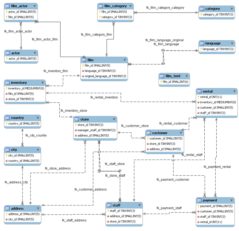
The object notation style used in
Figure 7.45, “The sakila EER Diagram” is Workbench (PKs
only). This notation only shows primary keys and no
other columns so it is especially useful where space is at a
premium. The relationship notation is the default, Crow's Foot.
As the connection lines show, each table is related to at least
one other table in the database (with the exception of the
film_text table). Some tables have two foreign
keys that relate to the same table. For example the
film table has two foreign keys that relate to
the language table, namely
fk_film_language_original and
fk_film_language. Where there is more than one
relationship between two tables, the connection lines run
concurrently.
Identifying and nonidentifying relationships are indicated by
solid and broken lines respectively. For example, the foreign key
category_id is part of the primary key in the
film_category table so its relationship to the
category table is drawn with a solid line. On
the other hand, in the city table, the foreign
key, country_id, is not part of the primary key
so the connection uses a broken line.
The printing options are used to create printouts of your EER Diagrams and are found under the menu. For creating documentation of your models see Section 7.5.1.5.1, “The DBDoc Model Reporting Dialog Window (Commercial Version)”.
The printing menu options are grayed if an EER Diagram is not active. The menu options are as follows:
Use this option to choose the paper size, orientation, and margins.
Use this option to send your EER Diagram directly to the printer. This option generates a preview before printing. From the preview you can adjust the scale of the view and also choose a multi-page view. Clicking the printer icon at the top left of this window, prints the currently selected EER Diagram. Close the print preview window if you need to adjust the placement of objects on the EER Diagram canvas.
Use this option to create a PDF file of your EER Diagram.
Use this option to create a PostScript file of your EER Diagram.
MySQL Workbench provides validation modules so that you can test your models before implementing them.
The validation plugins are accessed from the menu option. One plugin performs general validation for any Relational Database Management System (RDMS) and the other is MySQL-specific. Beneath these menu items are a number of specific validation tests. Running any one of these tests opens an output window docked at the bottom of the application. Warning messages are displayed on the left side of this window and the tests performed are displayed on the right.
The tasks performed by the validation modules are outlined in what follows.
The types of validation and examples that violate validation are listed in what follows:
Empty Content validation
A table with no columns
A routine or view with no SQL code defined
A routine group containing no routines
A table, view, or routine not referenced by at least one role
A user with no privileges
Objects such as tables that do not appear on at least one EER Diagram
Table Efficiency Validation
A table with no primary key
A primary key that does not use an integer-based data type
A foreign key that refers to a column with a different data type
Duplicated Identifiers Validation
Duplicate object names
Duplicate role or user names
Duplicate index or routine names
Consistency Validation
Use of the same column with columns of differing data types
Logic Validation
A foreign key that refers to a column other than the primary key in the source table
Any object that is object is either read- or write-only by role definition
Placeholder objects left over from reverse engineering
The types of MySQL-specific validation and examples that violate validation are listed in the following.
Integrity Violation
An object name longer than the maximum allowed
A foreign key defined for an engine type that doesn't support foreign keys (not yet implemented)
A view or routine that references a nonexistent table (not yet implemented)
A default value that does not match a column's data type
An invalid partitioning scheme
Syntax Violation
A routine, trigger, or view with incorrect SQL syntax
A reserved keyword used as an identifier
Use of an invalid character
This document aims to provide an overview of creating and modifying DBDoc Model Reporting templates, as used by MySQL Workbench.
The MySQL Workbench DBDoc Model Reporting system is based on the Google Template System. This document does not attempt to explain the Google Template System in detail. The Google document How To Use the Google Template System provides a useful overview of how the Google Template System works.
The templates employed by the DBDoc Model Reporting system are text
files that contain Markers. These text files are
processed by the template system built into MySQL Workbench, and the
markers replaced by actual data. The output files are then
generated. It is these output files, typically HTML or text, that
are then viewed by the user.
Markers can be of six types:
Template Include
Comment
Set delimiter
Pragma
Variable
Section start and Section end
The last two are the most commonly used in MySQL Workbench templates and these important markers will be briefly described in the following sections.
Variables
The use of variables in the templates is straightforward. Any variables denoted by markers in the template file, will be replaced by their corresponding data, prior to the output file being generated. The mapping between variables and their corresponding data is stored by MySQL Workbench in what is known as a Data Dictionary. In the data dictionary the variable name is the key and the variable's corresponding data is the value. The data dicionaries are built by MySQL Workbench and filled with the data contained in the model being processed.
By way of example, the following code snippet shows part of a template file:
Total number of Schemata: {{SCHEMA_COUNT}}In the generated output file the variable {{SCHEMA_COUNT}} will be replaced by the number of schemata in the model:
Total number of Schemata: 2
A variable can appear as many times as required in the template file.
Sections
Sections are used to perform iteration in the templates. When MySQL Workbench exchanges the variables in a section for data it will do so iteratively, using all data in the data dictionary in which the variable is defined. MySQL Workbench builds the data dictionaries according to the model currently being processed.
Again, this is best illustrated by example:
{{#SCHEMATA}}
Schema: {{SCHEMA_NAME}}
{{/SCHEMATA}}
In the previous code snippet the section start is indicated by the
{{#SCHEMATA}}marker. The end of the section is indicated by the{{/SCHEMATA}}marker. When the template is processed, MySQL Workbench will note the section and iterate the section until the variable data for{{SCHEMA_NAME}}in the corresponding data dictionary is exhausted. For example, if the model being processed contains two schemata, the output for the section might resemble the following:Schema: Airlines Schema: Airports
That is, the model contains two schemata, Airlines and Airports.
Data Dictionaries
It is important to understand the relationship between sections and data dictionaries in more detail. In a data dictionary the key for a variable is the variable name, a marker. The variable value is the variable's data. The entry for a section in a data dictionary is different. For a section entry in a data dictionary, the key is the section name, the marker. However, the value associated with the key is a list of data dictionaries. In MySQL Workbench each section is usually associated with a data dictionary. You can think of a section as activating its associated dictionary (or dictionaries).
When a template is processed, data dictionaries are loaded in a hierarchical pattern, forming a tree of data dictionaries. This is illustrated by the following table.
| Data Dictionary | Loads Data Dictionary |
|---|---|
| MAIN | SCHEMATA |
| SCHEMATA | TABLES, COLUMNS (Detailed is true), FOREIGN_KEYS (Detailed is true), INDICES (Detailed is true) |
| TABLES | REL_LISTING, INDICES_LISTING, COLUMNS_LISTING, TABLE_COMMENT_LISTING, DDL_LISTING |
| COLUMNS_LISTING | COLUMNS (Detailed is false) |
| REL_LISTING | REL (Detailed is false) |
| INDICES_LISTING | INDICES (Detailed is false) |
The root of the tree is the main dictionary. Additional dictionaries are then loaded from the root to form the dictionary tree.
If a template has no sections in it, then any variables used in the template will be looked up in the main dictionary. If a variable is not found in the main dictionary (which can be thought of as associated with the default, or main, section) then no data will be generated in the output file for that marker.
Evaluation of variables
The tree structure of the data dictionaries is important when it comes to evaluation of variables. As variables are defined in data dictionaries, their associated value only has meaning when that particular data dictionary is active, and that means when the section associated with that data dictionary is active. When a variable lookup occurs, the system will check the data dictionary associated with the current section. If the variable value can be found there the replacement is made. However, if the variable's value is not found in the current data dictionary then the parent data dictionary will be checked for the variable's value and so on up the tree until the main data dictionary, or root, is reached.
This can best be illustrated by an example. Assume we want to display the names of all columns in a model. Consider the following template as an attempt to achieve this:
    Report
    ------
    Column Name: {{COLUMN_NAME}}
This template will produce no output, even for a model that contains
many columns. In this example the only data dictionary active is the
main dictionary. COLUMN_NAME however is stored in
the COLUMNS data dictionary, which is associated
with the COLUMNS section.
With this knowledge the template can be improved as follows:
    Report
    ------
    {{#COLUMNS}}
    Column Name: {{COLUMN_NAME}}
    {{/COLUMNS}}
This still does not produce output. Referring to the table
Data Dictionary
Hierarchy Tree explains why. The COLUMNS
data dictionary has the parent dictionary
COLUMNS_LISTING.
COLUMNS_LISTING has the parent
TABLES, which has the parent
SCHEMATA, whose parent is the main dictionary.
Remember that for a dictionary to be involved in variable lookup,
its associated section must currently be active.
So to achieve the desired output we would need the template to be something like the following:
    Report
    ------

    {{#SCHEMATA}}
    {{#TABLES}}
    {{#COLUMNS_LISTING}}
    {{#COLUMNS}}
    Column Name: {{COLUMN_NAME}}
    {{/COLUMNS}}
    {{/COLUMNS_LISTING}}
    {{/TABLES}}
    {{/SCHEMATA}}
The following template is the same, but with explanatory comments added:
    Report
    ------

    {{! Main dictionary active}}
    {{#SCHEMATA}}  {{! SCHEMATA dictionary active}}
    {{#TABLES}}  {{! TABLES dictionary active}}
    {{#COLUMNS_LISTING}} {{! COLUMNS_LISTING dictionary active}}
    {{#COLUMNS}}  {{! COLUMNS dictionary active}}
    Column Name: {{COLUMN_NAME}} {{! COLUMN_NAME variable is looked-up, and found, in COLUMNS data dictionary}}
    {{/COLUMNS}}
    {{/COLUMNS_LISTING}}
    {{/TABLES}}
    {{/SCHEMATA}}
Imagine now that for each column name displayed you also wanted to display its corresponding schema name, the template would look like this:
    Report
    ------

    {{#SCHEMATA}}
    {{#TABLES}}
    {{#COLUMNS_LISTING}}
    {{#COLUMNS}}
    Schema Name: {{SCHEMA_NAME}} Column Name: {{COLUMN_NAME}}
    {{/COLUMNS}}
    {{/COLUMNS_LISTING}}
    {{/TABLES}}
    {{/SCHEMATA}}
When variable lookup is performed for SCHEMA_NAME
the COLUMNS dictionary will be checked. As the
variable is not found there the parent dictionary will be checked,
COLUMNS_LISTING, and so on until the variable is
eventually found, where it is held, in the
SCHEMATA dictionary.
If there are multiple schemata in the model the outer section will
be iterated over a matching number of times, and
SCHEMA_NAME will accordingly have the correct
value on each iteration.
It's important to always consider which dictionary needs to be active (and which parents) for a variable to be evaluated correctly. In the following section you will find a table that helps you identify section requirements.
A list of supported markers follows. These markers can be used in any template, including custom templates.
| Marker text | Type | Data Dictionary defined in (if variable) or parent dictionary (if section) | Corresponding data |
|---|---|---|---|
| TITLE | Variable | MAIN | Title of the report |
| GENERATED | Variable | MAIN | Date and time that the report was generated |
| STYLE_NAME | Variable | MAIN | The name of the style selected in MySQL Workbench. This is typically used to load the corresponding CSS file, depending on the name of the style selected in MySQL Workbench. |
| SCHEMA_COUNT | Variable | MAIN | The total number of schemata in the model |
| PROJECT_TITLE | Variable | MAIN | Project title as set for the model in . |
| PROJECT_NAME | Variable | MAIN | Project name as set for the model in . |
| PROJECT_AUTHOR | Variable | MAIN | Project author as set for the model in . |
| PROJECT_VERSION | Variable | MAIN | Project version as set for the model in . |
| PROJECT_DESCRIPTION | Variable | MAIN | Project description as set for the model in . |
| PROJECT_CREATED | Variable | MAIN | Automatically set for the model project, but as displayed in . |
| PROJECT_CHANGED | Variable | MAIN | Automatically set for the model project, but as displayed in . |
| TOTAL_TABLE_COUNT | Variable | MAIN | Total number of tables in all schemata contained in the model. |
| TOTAL_COLUMN_COUNT | Variable | MAIN | Total number of columns in all tables in all schemata in the model. |
| TOTAL_INDEX_COUNT | Variable | MAIN | Total number of indexes in the model. |
| TOTAL_FK_COUNT | Variable | MAIN | Total number of foreign keys in the model. |
| SCHEMATA | Section | MAIN | Used to mark the start and end of a SCHEMATA section. The SCHEMATA data dictionary becomes active in this section. |
| SCHEMA_NAME | Variable | SCHEMATA | The name of a schema in the model |
| SCHEMA_ID | Variable | SCHEMATA | The ID of the schema |
| TABLE_COUNT | Variable | SCHEMATA | Total total number of tables in the current schema |
| COLUMN_COUNT | Variable | SCHEMATA | The total number of columns in the current schema |
| INDICES_COUNT | Variable | SCHEMATA | The total number of indexes in the current schema |
| FOREIGN_KEYS_COUNT | Variable | SCHEMATA | The total number of foreign keys in the current schema |
| TABLES | Section | SCHEMATA | Marks the start and end of a TABLES section. The TABLES data dictionary becomes active in this section. |
| TABLE_NAME | Variable | TABLES | The table name |
| TABLE_ID | Variable | TABLES | The table ID |
| COLUMNS_LISTING | Section | TABLES | Marks the start and end of a COLUMNS_LISTING section. The COLUMNS_LISTING data dictionary becomes active in this section. |
| COLUMNS | Section | COLUMNS_LISTING | Marks the start and end of a COLUMNS section. The COLUMNS data dictionary becomes active in this section. |
| COLUMN_KEY | Variable | COLUMNS | Whether the column is a primary key or not |
| COLUMN_NAME | Variable | COLUMNS | The name of the column |
| COLUMN_DATATYPE | Variable | COLUMNS | The data type of the column |
| COLUMN_NOTNULL | Variable | COLUMNS | Whether or not the column allows NULLs |
| COLUMN_DEFAULTVALUE | Variable | COLUMNS | The default value of entries in this column |
| COLUMN_COMMENT | Variable | COLUMNS | Any comment for this column |
| COLUMN_ID | Variable | COLUMNS | The ID of the column |
| COLUMN_KEY_PART | Variable | COLUMNS (if detailed) | The type of column key |
| COLUMN_NULLABLE | Variable | COLUMNS (if detailed) | Can the column contain NULLs |
| COLUMN_AUTO_INC | Variable | COLUMNS (if detailed) | Does the column auto-increment |
| COLUMN_CHARSET | Variable | COLUMNS (if detailed) | The character set used by the column |
| COLUMN_COLLATION | Variable | COLUMNS (if detailed) | The collation used by the column |
| COLUMN_IS_USERTYPE | Variable | COLUMNS (if detailed) | Whether or not the column is a user type |
| INDICES_LISTING | Section | TABLES | Marks the start and end of an INDICES_LISTING section. The INDICES_LISTING data dictionary becomes active in this section. |
| INDICES | Section | INDICES_LISTING | Marks the start and end of an INDICES section. The INDICES data dictionary becomes active in this section. |
| INDEX_NAME | Variable | INDICES | The name of the index |
| INDEX_PRIMARY | Variable | INDICES | Is this a primary index |
| INDEX_UNIQUE | Variable | INDICES | Is this a unique index |
| INDEX_TYPE | Variable | INDICES | The type of index e.g. PRIMARY |
| INDEX_KIND | Variable | INDICES | The kind of index |
| INDEX_COMMENT | Variable | INDICES | A comment for the index |
| INDEX_ID | Variable | INDICES | The ID of the index |
| INDEX_COLUMNS | Section | INDICES | Marks the start and end of an INDEX_COLUMNS section. The INDEX_COLUMNS data dictionary becomes active in this section. |
| INDEX_COLUMN_NAME | Variable | INDEX_COLUMNS | The index column name |
| INDEX_COLUMN_ORDER | Variable | INDEX_COLUMNS | The index column order e.g. ascending, descending |
| INDEX_COLUMN_COMMENT | Variable | INDEX_COLUMNS | A comment for the index column |
| INDEX_KEY_BLOCK_SIZE | Variable | INDEX_COLUMNS (if detailed) | Index key block size |
| REL_LISTING | Section | TABLES | Marks the start and end of a REL_LISTING section. The REL_LISTING data dictionary becomes active in this section. |
| REL | Section | REL_LISTING | Marks the start and end of a REL section. The REL data dictionary becomes active in this section. |
| REL_NAME | Variable | REL, FOREIGN_KEYS | Relationship name |
| REL_TYPE | Variable | REL, FOREIGN_KEYS | Relationship type |
| REL_PARENTTABLE | Variable | REL, FOREIGN_KEYS | Parent table of relationship |
| REL_CHILDTABLE | Variable | REL, FOREIGN_KEYS | Child table of relationship |
| REL_CARD | Variable | REL, FOREIGN_KEYS | Relationship card |
| FOREIGN_KEY_ID | Variable | REL | Foreign key ID |
| FOREIGN_KEYS | Section | SCHEMATA | Marks the start and end of a FOREIGN_KEYS section. The FOREIGN_KEYS data dictionary becomes active in this section. |
| FK_DELETE_RULE | Variable | FOREIGN_KEYS | Foreign key delete rule |
| FK_UPDATE_RULE | Variable | FOREIGN_KEYS | Foreign key update rule |
| FK_MANDATORY | Variable | FOREIGN_KEYS | Foreign key mandatory |
| TABLE_COMMENT_LISTING | Section | TABLES | Marks the start and end of a TABLE_COMMENT_LISTING section. The TABLE_COMMENT_LISTING data dictionary becomes active in this section. |
| TABLE_COMMENT | Variable | TABLE_COMMENT_LISTING | A comment for the table |
| DDL_LISTING | Section | TABLES | Marks the start and end of a DDL_LISTING section. The DDL_LISTING data dictionary becomes active in this section. |
| DDL_SCRIPT | Variable | DDL_LISTING | Display the DDL script of the currently active entity e..g. SCHEMATA, TABLES |
Using the table
The table shows which variables are defined in which sections. The variable should be used in its correct section, otherwise its value will not be displayed.
It should be remembered though that the data dictionaries used to perform the lookup form a hierarchical tree, so it is possible to use a variable defined in a parent section, in a child section.
In the simplest case a template consists of two files. A template
file, which has a .tpl extension, and a
special file info.xml. The
info.xml file has important metadata about
the template. A third file is optional, that is the preview image
file. This preview file provides a thumbnail image illustrating
the appearance of the generated report.
One of the easiest ways to create a custom template is to make a copy of any existing template.
For example, you make a custom template based on the Text
Basic. The following procedure demonstrates this.
First you need to make a copy of the template on which you are going to base your custom template. To do this navigate to the folder where the templates are stored. Assuming MySQL Workbench has been installed into the default location on Windows, this would be
C:\Program Files\MySQL\MySQL Workbench 5.0 SE\modules\data\wb_model_reporting.Then make a copy of the template folder you wish to base your new template on. In this case a copy of the
Text_Basic.tplfolder is made. The copy can be given any suitable name, for example,Custom_Basic.tpl.Now the
info.xmlfile needs to be edited, to reflect your custom template. The unedited file in this case is shown here:<?xml version="1.0"?> <data> <value type="object" struct-name="workbench.model.reporting.TemplateInfo" id="{BD6879ED-814C-4CA3-A869-9864F83B88DF}" struct-checksum="0xb46b524d"> <value type="string" key="description">A basic TEXT report listing schemata and objects.</value> <value type="string" key="name">HTML Basic Frame Report</value> <value type="list" content-type="object" content-struct-name="workbench.model.reporting.TemplateStyleInfo" key="styles"> <value type="object" struct-name="workbench.model.reporting.TemplateStyleInfo" id="{7550655C-CD4B-4EB1-8FAB-AAEE49B2261E}" struct-checksum="0xab08451b"> <value type="string" key="description">Designed to be viewed with a fixed sized font.</value> <value type="string" key="name">Fixed Size Font</value> <value type="string" key="previewImageFileName">preview_basic.png</value> <value type="string" key="styleTagValue">fixed</value> </value> </value> <value type="string" key="mainFileName">report.txt</value> </value> </data>Two objects are defined in the file. The
TemplateInfoobject and theTemplateStyleInfoobject. These objects contain information about the template that will be displayed in the DBDoc Model Reporting wizard main screen.The first thing you need to change are the object GUIDs that are used in the file. In this example there are two that need replacing:
id="{BD6879ED-814C-4CA3-A869-9864F83B88DF}"
...
id="{7550655C-CD4B-4EB1-8FAB-AAEE49B2261E}"
Generate two new GUIDS. This can be done using any suitable command-line tool. There are also free online tools that can be used to generate GUIDs. The
info.xmlfile should then be edited accordingly.Edit the textual information for the
TemplateInfoandTemplateStyleInfoobjects to reflect the purpose of the custom template.The modified file will now look something like the following:
<?xml version="1.0"?>
<data>
  <value type="object" struct-name="workbench.model.reporting.TemplateInfo"
  id="{cac9ba3f-ee2a-49f0-b5f6-32580fab1640}" struct-checksum="0xb46b524d">
    <value type="string"
    key="description">Custom basic TEXT report listing schemata and objects.</value>
    <value type="string" key="name">Custom Basic text report</value>
    <value type="list" content-type="object"
    content-struct-name="workbench.model.reporting.TemplateStyleInfo" key="styles">
      <value type="object"
      struct-name="workbench.model.reporting.TemplateStyleInfo"
      id="{39e3b767-a832-4016-8753-b4cb93aa2dd6}" struct-checksum="0xab08451b">
        <value type="string" key="description">Designed to be viewed with a fixed sized font.</value>
        <value type="string" key="name">Fixed Size Font</value>
        <value type="string" key="previewImageFileName">preview_basic.png</value>
        <value type="string" key="styleTagValue">fixed</value>
      </value>
    </value>
    <value type="string" key="mainFileName">custom_report.txt</value>
  </value>
</data>
The next step is to create the new template file. Again this may best be achieved, depending on your requirements, by editing an existing template. In this example the template file
report.txt.tplis shown here:+--------------------------------------------+ | MySQL Workbench Report | +--------------------------------------------+ Total number of Schemata: {{SCHEMA_COUNT}} ============================================= {{#SCHEMATA}} {{SCHEMA_NR}}. Schema: {{SCHEMA_NAME}} ---------------------------------------------- ## Tables ({{TABLE_COUNT}}) ## {{#TABLES}}{{TABLE_NR_FMT}}. Table: {{TABLE_NAME}} {{#COLUMNS_LISTING}}## Columns ## Key Column Name Datatype Not Null Default Comment {{#COLUMNS}}{{COLUMN_KEY}}{{COLUMN_NAME}}{{COLUMN_DATATYPE}} » {{COLUMN_NOTNULL}}{{COLUMN_DEFAULTVALUE}}{{COLUMN_COMMENT}} {{/COLUMNS}}{{/COLUMNS_LISTING}} {{#INDICES_LISTING}}## Indices ## Index Name Columns Primary Unique Type Kind Comment {{#INDICES}}{{INDEX_NAME}}{{#INDICES_COLUMNS}}{{INDEX_COLUMN_NAME}} » {{INDEX_COLUMN_ORDER}}{{INDEX_COLUMN_COMMENT}}{{/INDICES_COLUMNS}} » {{INDEX_PRIMARY}}{{INDEX_UNIQUE}}{{INDEX_TYPE}}{{INDEX_KIND}}{{INDEX_COMMENT}} {{/INDICES}}{{/INDICES_LISTING}} {{#REL_LISTING}}## Relationships ## Relationship Name Relationship Type Parent Table Child Table Cardinality {{#REL}}{{REL_NAME}}{{REL_TYPE}}{{REL_PARENTTABLE}}{{REL_CHILDTABLE}}{{REL_CARD}} {{/REL}}{{/REL_LISTING}} --------------------------------------------- {{/TABLES}} {{/SCHEMATA}} ============================================= End of MySQL Workbench ReportThis template shows details for all schemata in the model.
The above template file can be edited in any way you like, with new markers being added, and existing markers being removed as required. For the custom template example you might want to create a much simpler template. Such as the one following:
+--------------------------------------------+
| MySQL Workbench Custom Report              |
+--------------------------------------------+

Total number of Schemata: {{SCHEMA_COUNT}}
=============================================
{{#SCHEMATA}}
Schema Name: {{SCHEMA_NAME}}
----------------------------------------------
## Tables ({{TABLE_COUNT}}) ##

{{#TABLES}}
Table Name: {{TABLE_NAME}}
{{/TABLES}}
{{/SCHEMATA}}

Report Generated On: {{GENERATED}}
=============================================
End of MySQL Workbench Custom Report
This simplified report just lists the schemata and the tables in a model. The date and time the report was generated will also be displayed as a result of the use of the
{{GENERATED}}variable.The custom template can then be tested. Start MySQL Workbench, load the model to generate the report for, select the , menu item. Then select the new custom template from the list of available templates, select an output directory and then click to generate the report. Finally, navigate to the output directory to view the finished report.