| C H A P T E R 2 |
|
Installing the System |
This chapter explains how to install a Sun StorEdge base cabinet and one or two optional expansion cabinets. It also explains how to initially configure a newly installed system. It includes the following sections:
Before you can begin to install the system, you need to make sure that you prepare the installation site, set up a DHCP server if you want to use dynamic IP addressing, check the contents of the ship kit, and review the installation task summary.
You must complete all of the installation preparation tasks described in the Sun StorEdge 6920 System Site Preparation Guide, including:
|
Note - If you do not have a copy of the Sun StorEdge 6920 System Site Preparation Guide, you can download it from the Sun web site, as described in Accessing Sun Documentation. |
The Sun StorEdge 6920 system supports both dynamic and static IP addressing. Dynamic IP addressing requires a Dynamic Host Configuration Protocol (DHCP) server installed at your site and configured for the Sun StorEdge 6920 system.
If you want to use dynamic IP addressing, refer to the Solaris OS system administrator guide for information about configuring DHCP. When configuring DHCP for the Sun StorEdge 6920 system, binding must be persistent, not dynamic.
As an alternative, if you do not have a DHCP server, you can assign a static IP address to the system. If you are using fixed IP addressing, obtain an IP address from your network administrator.
The Sun StorEdge 6920 system and accessory ship kit are packaged together in one shipping carton. To unpack your system:
1. Unpack the cabinet as described in the unpacking guide attached to the outside of the shipping carton.
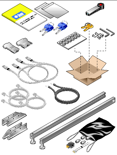
2. Unpack the ship kit box that is attached to the side of the cabinet and check its contents (see TABLE 2-1 and FIGURE 2-1).
|
Black bag containing the SSRR Global Telco adapter kit; includes country specific telephone adapters and telephone cord with 4-pin connectors |
||
Two power cables (P/N 180-1954-nn) are located inside the base cabinet with one of the following connector types:
3. Locate the two Allen wrenches packed in the hardware kit box inside the ship kit. You need both wrenches to remove the cabinet from the shipping pallet.
4. Follow the instructions in the unpacking guide to remove the cabinet from the shipping pallet.
Use the following checklist as your guide to installing the Sun StorEdge 6920 system. To ensure a successful installation, perform the tasks in the order in which they are presented.
|
7. If you want to use dynamic IP addressing, set up and configure the DHCP server. |
System administrator's guide for the server's operating system |
|
|
9. Connect the system to the Sun StorEdge Remote Response service. |
||
|
10. Log in to the Java Web Console and start the management software. |
||
|
Starting the Storage Automated Diagnostic Environment Enterprise Edition |
||
|
16. Cable the management host and install the data host software on a remote host. |
||
|
17. Set up Sun Storage Automated Diagnostic Environment Enterprise Edition. |
Sun Storage Automated Diagnostic Environment Enterprise Edition Release Notes Version 2.4 |
|
This section covers the main requirements for installing the base cabinet:
TABLE 2-2 lists the items you need to complete the tasks in this section.
|
7/16-inch ratchet wrench for attaching floor-mounting brackets |
||
|
1/2-inch ratchet wrench for attaching floor-mounting brackets |
You must install the Sun StorEdge 6920 system in accordance with the local safety codes and regulations. This section contains additional safety information for the local facility.
1. Measure cabling distances to ensure that the supplied cable is adequate.
The grounding cable for the cabinet is 6.5 feet (~2 meters) long.
Refer to the product specifications in the Sun StorEdge 6920 System Site Preparation Guide when you are determining where to place the cabinet.
2. Move the base cabinet into position.
The base cabinet has wheels. Plan to have two or three people available to move the cabinet into position, one to push the system off the pallet and onto the ramp, and the others to offer resistance so that the cabinet does not roll. Make sure there is adequate space in front of the cabinet to ensure that it will not roll into anything. Move the cabinet slowly and make sure the floor is free of objects and cables.
3. Secure the base cabinet in position.
To minimize personnel injury in the event of a seismic occurrence, you should securely fasten the cabinet to a rigid structure extending from the floor to the ceiling or to the walls of the room in which you place the cabinet.
Install the cabinet on a level surface. There are adjustable nonskid pads at each corner of the cabinet base. Extend these pads when the cabinet is installed to prevent the unit from rolling. Do not use these pads to level the cabinet.
4. Ensure that the base cabinet has proper ventilation.
Air cools the cabinet from front to back. Air enters at the front, circulates through the system, and is expelled at both the top and back of the cabinet. Position the cabinet so as to ensure proper ventilation.

|
Caution - Do not block or cover the openings of the cabinet, and do not place it near a radiator or heat register. |
The floor-mounting brackets enable you to bolt the cabinet to the floor. If you do not install the floor-mounting brackets, then you must install the stabilizer legs. The stabilizer legs are extended to prevent the cabinet from tipping over when field-replaceable units (FRUs) are installed, removed, or serviced.
To stabilize the base cabinet, you must perform one of the following procedures:
Unless you are using the floor-mounting brackets, the four leveling pads must be lowered to the floor for the cabinet to meet the Underwriters Laboratories physical stability requirements.
The stabilizer legs help prevent the system from tipping over when field-replaceable units (FRUs) are serviced in the system. The stabilizer legs must be properly installed and set to be effective.
If you want to attach the system directly to the floor, skip to Installing the Floor-Mounting Brackets.
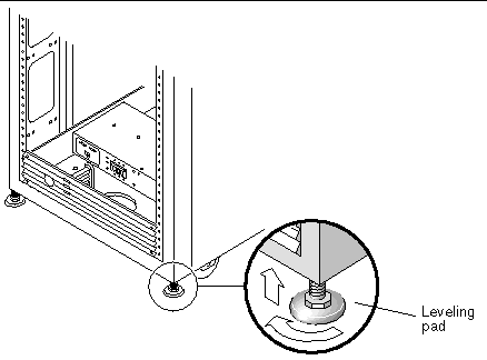
The leveling pads (screws) are located at each corner at the base of the cabinet (FIGURE 2-2).
1. Open the back door of the base cabinet and remove the leveling wrench from the inside of the cabinet.
The wrench is attached to the left rack rail.
2. Adjust the four leveling pads on the cabinet frame using the leveling wrench (FIGURE 2-2).
Ensure that the four pads press against the floor so that the cabinet does not move or rock in any direction.
3. Continue with the next section, "Installing the Stabilizer Legs" to help prevent the base cabinet from tipping over when field-replaceable units (FRUs) are serviced.

|
Caution - Always extend the stabilizer legs before attempting to install new FRUs or to service FRUs in the system. |
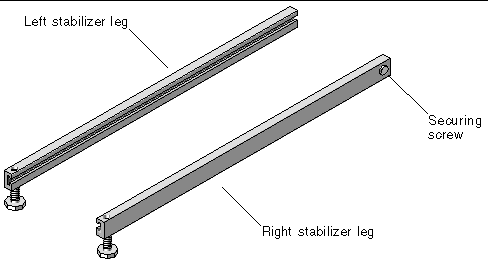
1. Use a slotted screwdriver to loosen the securing screw on the right stabilizer leg (FIGURE 2-3).
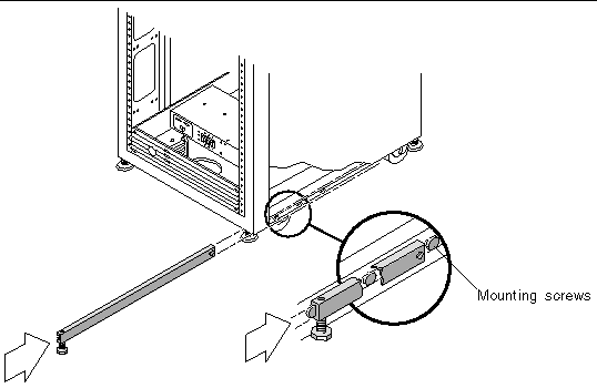
2. Insert two mounting screws to each side of the cabinet (FIGURE 2-3).
One mounting screw is already in place.
3. Slide the right stabilizer leg over the three mounting screws at the bottom of the system cabinet (FIGURE 2-4) and fully extend it.
4. Tighten the securing screw.
This prevents the stabilizer leg from falling off the mounting screws when it is extended.
5. Repeat Step 1 through Step 4 for the left stabilizer leg.
6. Use the leveling wrench to adjust the feet on both stabilizer legs so that they touch the floor (FIGURE 2-5).
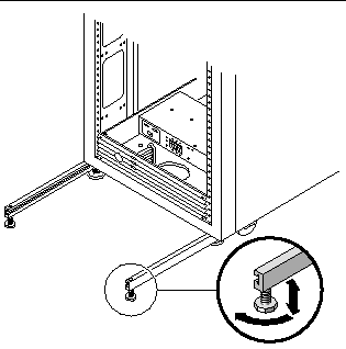
7. Slide both stabilizer legs under the system cabinet.
Skip this section if you have installed the stabilizer legs and adjusted the leveling pads.
Use the four floor-mounting brackets to attach the system to the floor. The bolts to secure the floor-mounting brackets are included in the hardware kit box inside the ship kit.

|
Caution - Do not bolt the floor-mounting brackets to the deck plating of a raised (computer-room) floor, because this would result in an unstable mount. |
|
Note - If you are installing the floor-mounting brackets over previously installed threaded rods, loosely attach the floor-mounting brackets to the rods and then to the system. |
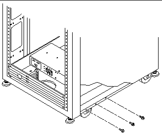
1. Remove the mounting screws from the bottom right and left sides of the cabinet (FIGURE 2-6).
2. Using a 7/16-inch ratchet wrench and the mounting screws you just removed, attach the right floor-mounting brackets to the front and back of the system (FIGURE 2-7).
Additional mounting screws, if needed, are packed in the ship kit.
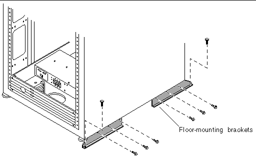
3. Bolt the right floor-mounting brackets to the floor.
4. Repeat Step 1 through Step 3 for the left floor-mounting brackets.
If you purchased a Sun StorEdge 6920 system with one or two expansion cabinets, follow the instructions in the following sections to connect the expansion cabinets to the base cabinet:

|
Caution - You must connect the expansion cabinet before connecting power to the base cabinet. |
TABLE 2-3 lists the items that are required for completing the tasks in this section:
|
Quantity [1] |
|||
|---|---|---|---|
|
10-meter cables to connect the base cabinet service panel to the expansion cabinet service panel |
Expansion cabinet ship kit [2] |
||
The base cabinet service panel has two sets of Fibre Channel (FC) ports (EXP 1 and
EXP 2) to connect to the expansion cabinets (see FIGURE 2-8). The expansion cabinet service panel has redundant FC ports (see FIGURE 2-9).
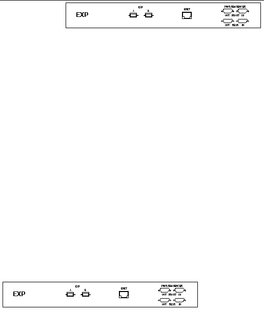
Connect redundant Fibre Channel (FC) cables (part number 537-1060-01) as follows (see FIGURE 2-9):
Connect redundant Fibre Channel (FC) cables (part number 537-1060-01) as follows (see FIGURE 2-10):
To connect to one or two expansion cabinets, use one Ethernet cable (10M RJ-45/RJ-45 crossover, part number 530-3138-01) for each expansion cabinet as shown in FIGURE 2-11 or FIGURE 2-12.
If you are setting up the system to enable remote power management, you must also connect two or four power sequencer serial cables (part number 530-3210-01) between the base cabinet and one or both expansion cabinets as shown in FIGURE 2-11 or FIGURE 2-12.
This section covers the procedures for cabling and powering on the system for the first time. You must complete the following three procedures in consecutive order to correctly power on the system:
|
Note - If you want to enable the system for lights-out management, which allows you to perform a remote partial system shutdown, go to Preparing the System for Remote Power Management. |
TABLE 2-4 lists the items required for performing the tasks in this section.
You must connect the grounding cable to either a grounding post or something attached to a grounding post. The system is designed to work with single-phase power systems that have a grounded neutral conductor.
1. Open the front and back doors of the base cabinet.
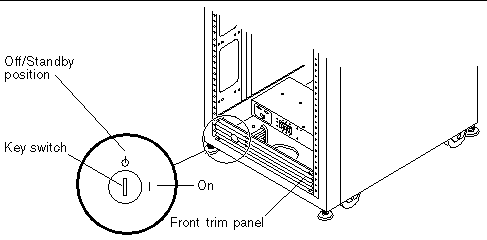
2. Insert a key into the Standby/On key switch at the bottom of the front panel (FIGURE 2-13).
|
Note - The position of the key switch does not matter for local power-on and power-off operations (FIGURE 2-13). If you want to enable remote power management, set the key to the Standby position and refer to Preparing the System for Remote Power Management for instructions. |
3. Remove the front trim panel and set it aside.
4. Locate the 6.5-foot (~2-meter) grounding cable in the ship kit.
5. Attach one end of the grounding cable to the front AC power sequencer on the cabinet (FIGURE 2-14). Feed the cable through the opening at the bottom of the cabinet.
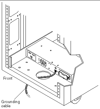
6. Attach the other end of the grounding cable to either an external grounding post or something attached to a grounding post.
You are now ready to connect the power cables, as described in the next section.
1. Verify that the front and back AC power sequencer circuit breakers are both in the Off position (FIGURE 2-15).
2. Verify that the Local/Off/Remote switch is in the Remote position on each power sequencer (FIGURE 2-15).
3. Check the electrical ratings label on the serial number label attached to the power sequencer. Verify that the stated rating of each power sequencer matches the AC input voltage to the system (see "Power Sequencer Electrical Specifications" in the Sun StorEdge 6920 System Site Preparation Guide).
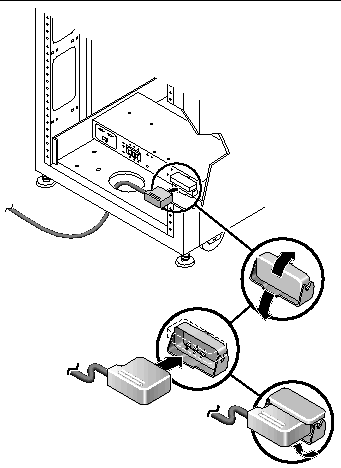
4. Connect each power cable to the front and rear power sequencers (FIGURE 2-16):
a. Route each power cable directly through the opening in the base of the cabinet.
b. Flip open the latch covers of each cable to access the connectors.
c. Connect the female end of one power cable to the rear power sequencer connector.
d. Connect the female end of the other power cable to the front power sequencer connector.
e. Pull the latch covers over the power cables to secure them to the power sockets.
5. Connect the other end of each power cable to a grounded outlet.
One of the following connector types is provided on the power cables:

|
Caution - To reduce the risk of electric shock, strictly observe all Caution and Note statements in the following procedure. |
After you have connected the power cables, you are ready to power on the system, as described in the next section.

|
Caution - To avoid damage to internal circuits, do not connect or disconnect any cable while the FRU associated with the cable is powered on. |
1. Verify that the AC power cable of the system is connected to the correct AC outlet.

|
Caution - Do not disconnect the AC power cable from the outlet when working on or in the system. This connection provides a grounding path that prevents damage from electrostatic discharge. |
2. At the front and back of the base cabinet, set the AC power sequencer circuit breakers to the On position (FIGURE 2-15).
3. Verify that the Power Available LED on both the front and back AC power sequencer panels are green.
4. Wait approximately one minute after the AC power sequencer circuit breakers are pressed on.
As soon as you connect AC power to the system, the Storage Service Processor powers on.
5. At the front and back of the system, set the Local/Off/Remote switch to the Local position. If you want to enable the system for remote power managment, set the switch to the Remote position and see Preparing the System for Remote Power Management for more information.
6. Verify that the Switched Outlet LEDs on the front and back AC power sequencer panels are green.
|
Note - The Storage Service Processor and Storage Service Processor accessory tray are already powered on because they are connected to the unswitched power outlets. |
7. Replace the front trim panel at the bottom front of the cabinet.
8. Turn the key switch, located at the bottom of the front panel, to the On position (FIGURE 2-13).
All three LEDs on the front AC power sequencer panel should be green (FIGURE 2-17).
If any of the LEDs are not green, refer to Appendix D.
The Sun StorEdge 6920 system is packaged with a universal serial bus (USB) flash disk to back up the Storage Service Processor configuration files. In the event of a Storage Service Processor failure, field service personnel can use the flash disk to restore the original configuration on a replacement Storage Service Processor.
The flash disk provided with the system is one of the models described in the following table.
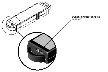
1. If the USB flash disk has a write protection switch, verify that it is set to the unlock (write-enabled) symbol.
The flash disk is write-enabled when the write protection switch is set to the unlock position (FIGURE 2-18).
|
Note - If your flash disk is a different model, refer to the Sun StorEdge 6920 System Release Notes for details. |
2. At the back of the base cabinet, loosen the two thumb screws on the right side of the service panel and carefully swing open the service panel.
3. Remove the round protective cover from the disk.
4. Insert the USB flash disk into the USB port 0 on the back panel of the Storage Service Processor.

5. To verify that the flash disk is installed correctly, look for a steady LED located at the top of the disk.
|
Note - The LED is located on the top of the flash disk and might be difficult to see when it is installed. |
6. Close the service panel and tighten the two thumb screws.
You configure the initial system by establishing a serial connection to the system and running the setup script.
The following items from the ship kit are required:
1. Locate the serial cables that came with the system.
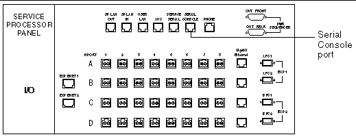
2. If necessary, assemble the RJ-45 cable with the adapter that fits either the DB9 or the DB25 serial port of a laptop, terminal, or Solaris workstation. (See Serial Console Port Interface for more information.)
3. Connect the serial cable from the Serial Console port on the service panel to your laptop, terminal, or workstation (FIGURE 2-20).
4. Configure the console settings:
You establish the initial configuration of the Sun StorEdge 6920 system by logging in to the system through the serial connection from a Sun workstation, a PC, or another terminal type.
This procedure explains how to establish the serial connection, log in through the Serial Console port, and run the initial configuration script. This script guides you through the configuration steps for a new system.
Before you start the configuration script, collect the required system and network information using the Information Collection Worksheet as your guide.
1. Log in to the network terminal concentrator (NTC) using the following login name and password:
2. Switch to the system's Storage Service Processor.
3. Press Return several times until the login prompt is displayed.
4. Log in to the console using the following login name and password:
When you log in as setup, the initial configuration utility script automatically runs.
5. Select Initial configuration from the list of options by entering 1.
6. The script prompts you to enter a system ID from 0 to 7.
If this is the first Sun StorEdge 6920 system at your site, enter 0 or press Return. You can have a maximum of eight systems in one configuration (sp0 through sp7). If more than one Sun StorEdge 6920 system is installed at your site, use the next highest number in sequence for each installed system.
|
Note - If you have multiple Sun StorEdge 6920 systems and want the Sun StorEdge Remote Response service to monitor the systems through a common telephone line, you must assign each Storage Service Processor a unique ID. The system containing the modem with the telephone line connection must be assigned a system ID of sp0. For more information about connecting multiple systems, see Connecting Multiple Systems. |
7. Select the dynamic host control protocol (DHCP) IP or fixed IP addressing option.
If you are using a DHCP server to assign the IP address, you are prompted to enter the nameserver IP address and domain name. When configuring DHCP, be sure that binding is persistent, not dynamic.
8. If you do not have a DHCP server, enter 2 to configure a fixed (or static) IP address for the system.
Network Settings: -------------------- Do you wish to use DHCP or Fixed Network Addresses? 1. DHCP 2. Fixed Your Choice [2]: 2 |
9. If you selected Fixed, enter the following network settings. Press Return to accept the defaults.
10. If necessary, modify the time zone.
Enter 1 to select your time zone from a list, enter 2 and enter the time zone, or enter 3 if no changes are needed.
11. If necessary, modify the current date and time.
Enter 1 to change the date and time. Enter the date in mm/dd/yyyy format and enter the time in one of the formats shown in the following example:
12. When prompted, verify the accuracy of your responses.
Enter y or press the Return key to start the automatic configuration.
If you enter n, you are prompted for the network configuration again. If you press Return at each question, your original answer is retained.
The following output is displayed.
The initial configuration is complete when the console login prompt is displayed.
|
Note - If any alarms appear, you can clear them later as described in Responding to Current Alarms. |
13. Disconnect the serial connection. If you are connected through tip, disconnect from the serial connection by entering the following command:
The terminal session returns to the shell.
14. Disconnect the serial cable from the Serial Console port.
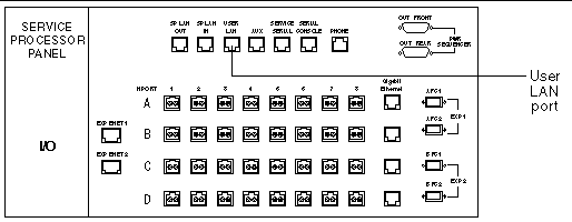
When the system is connected to your local area network (LAN) through the User LAN port on the service panel, the system can be managed through a browser from any workstation on the network.
The firewall that connects to the User LAN port supports a half-duplex 10-Mbps network connection. Configure the port settings on your network switch or hub to an auto-negotiate setting. If for some reason you cannot use an auto-negotiate setting, set the network switch or hub to half duplex 10 Mbps.
To connect the system to your LAN:
1. Locate the RJ-45 cable that is connected to your local area network.
2. Connect the RJ-45 cable to the User LAN port on the back of the service panel (FIGURE 2-21).
The Sun StorEdge Remote Response service provides remote monitoring of the Sun StorEdge 6920 system. When you activate this service, the Storage Service Processor continually monitors the messages sent to the system log by the software and firmware in the system subsystems. If a message contains an alert, the system contacts the Sun Service Center.
All of the hardware and software required for using the Sun StorEdge Remote Response service is included with the system. The modem installed in the base cabinet is qualified for use in most countries (see Supported Country Listing) with no modification required.
|
Note - If remote monitoring by means of the Sun StorEdge Remote Response service is not possible, configure RAS Telemetry for this system. The type of data sent includes information such as firmware levels, WWNs, serial numbers, event logs, and system uptime. Customer data is not sent. The telemetry data gathered allows Sun to know if your system requires implementation of a field information notice (FIN), field change order (FCO), or firmware upgrade. To set up encrypted email for RAS Telemetry, refer to the instructions in Setting Site Information for Diagnostics and Monitoring to configure the Network Storage Command Center (NSCC) remote provider service. |
To set up the remote response service at your site:
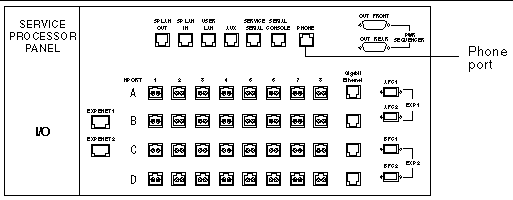
1. Connect a dedicated analog telephone line with dial-out and dial-in capability. Connect the telephone line to the Phone port on the service panel of the base cabinet (FIGURE 2-22).
|
Note - To install and configure an external modem, use the procedures in Sun Storage Automated Diagnostic Environment > Service Advisor > X-Options > Adding External Modem. |
2. Gather the information you need for activating the service, using the Remote Response Service Worksheet as your guide.
3. To activate the remote service, contact your local Sun Service Center and ask for Sun StorEdge Remote Response installation activation.
4. Set up an SSRR notification provider, as described in Setting Site Information for Diagnostics and Monitoring.
If you want to connect multiple Sun StorEdge 6920 systems to share a single telephone line, you must first complete the installation and initial configuration of the first system. You can then connect additional Sun StorEdge 6920 systems, as described in Connecting Multiple Systems. If you want to connect the Sun StorEdge 6920 system to a Sun StorEdge 6320 system, contact the Sun Service Center.
At this point, you have completed the hardware installation and initial system configuration. The system is connected to the network, you have named the system, and you have set the correct date, time, and time zone.
You have also connected cables to the service panel for the Sun StorEdge Remote Response service, if applicable.
The next step is to log in to the system using a web browser and complete the initial configuration, as described in Logging In and Completing the Initial Configuration.
Copyright © 2005, Sun Microsystems, Inc. All Rights Reserved.