| Skip Navigation Links | |
| Exit Print View | |

|
Sun Fire X4640 Server Service Manual Sun Fire X4640 Server Documentation Library |
| Skip Navigation Links | |
| Exit Print View | |

|
Sun Fire X4640 Server Service Manual Sun Fire X4640 Server Documentation Library |
About This Documentation (PDF and HTML)
Sun Fire X4640 Server Service Manual Overview
Controlling Power and Performing Hardware Reset
Powering the Server On and Off
Controlling Server Power Remotely
Resetting the Server Using the Reset Switch (SW2)
Removing and Installing Components
Antistatic Procedures and Precautions
Tools Required for Servicing the Sun Fire X4640 Server
Preparing the Server for Service and Operation
Removal and Replacement Procedures
List of Customer Replaceable Units and Field Replaceable Units
Replacing the CMOS Battery (CRU)
Replacing or Adding a Hard Drive (CRU)
Replacing a CPU Module and Filler Card (CRU)
Replacing or Adding DIMMs (CRU)
Replacing or Adding PCI Cards (CRU)
Replacing or Adding a Power Supply (CRU)
Replacing the Service Processor Board (FRU)
Replacing the DVD Module (FRU)
Replacing the Power Distribution Board (FRU)
Replacing the Fan Tray Carriage (FRU)
Replacing the Front Panel Indicator Board (FRU)
Replacing the Front I/O Board (FRU)
Replacing a Hard Disk Backplane (FRU)
Replacing the Motherboard (FRU)
Motherboard Connectors and Fasteners
How to Install the Motherboard
Updating Field-Replaceable Unit Information
How To Update Motherboard FRU Information
How to Update CPU Module FRU Information
How to Update the Server CPLDs
Configuring the System Using the BIOS Setup Utilities
BIOS and the BIOS Setup Utility
How to Configure the System BIOS
BIOS and Service Processor Updates
LSI BIOS Configuration Utility
Sun Fire X4640 Server References and Specifications
Sun Fire X4640 Server Features and Components
Sun Fire X4640 Server Front and Back Panel Features and Components
Sun Fire X4640 Server Specifications
Sun Fire X4640 Server Motherboard Jumpers and Switches
Sun Fire X4640 Server External LED Locations and Meanings
Before You Begin
If you are replacing a motherboard that is not dead, obtain the BIOS and ILOM versions and download the system software release package (combined BIOS/ILOM) that incorporates those versions. A system software release package can be downloaded from: http://support.oracle.com.
If you are replacing a dead motherboard, obtain the ILOM version and download the system software release package (combined BIOS/ILOM) that incorporates that version. A system software release package can be downloaded from: http://support.oracle.com.
Copy down the motherboard serial number information.


The metal door stays open when you slide it up into the retaining clips.

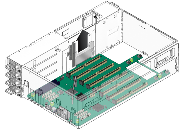
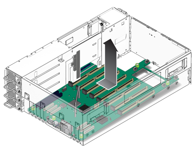
 | Caution - When lifting the board, avoid damaging the light pipes and connectors on the rear edge of the motherboard. |

Underneath the motherboard is a sheet of mylar insulation. This insulation must stay with the chassis. Do not remove it with the motherboard.
The mylar insulation should lie flat. It is stamped to fit within the chassis and uses the standoff and support pegs for alignment.
Next Steps