Developing Java CAPS Projects
A Project represents a logical system designed to implement either all or part of a business integration task. The basic functionality of a Project is processing and routing messages, which it accomplishes by means of Collaborations. Projects are created using tools contained within the NetBeans IDE, and are deployed to specific runtime Environments that represent the physical system supporting the software. Components developed for use in one Project can be used in another, and a Project can internally reference another Project.
With the release of Java CAPS 6, Projects can be either Repository-based or based on JavaTM Business Integration (JBI). With this release, you also create or open a top-level Repository-based project following the standard NetBeans pattern. Even though data for Repository-based Projects remains externally stored in the Repository, the projects appear as Project folders under the CAPSRepositoryProject directory. There is one folder for each top-level project, and these folders contain pointers to the Repository for each Java CAPS Project you create.
The CAPSRepositoryProject is synchronized with the top-level projects in the Repository each time the Repository is refreshed and each time NetBeans connects to the Repository. You can refresh the Repository by using the Tools > CAPS Repository > Refresh All menu item. Refreshing or connecting to the Repository downloads information from the Repository to the local CAPSRepositoryProject directory.
The following sections provide information on creating and opening a Repository-based top-level Project, and connecting Project components to each other. If you have any questions or problems, see the Java CAPS web site at http://goldstar.stc.com/support.
Procedures are described in the following topics:
Project components are discussed in the following topic :
Additional details about relevant features of the enhanced NetBeans IDE user interface are provided in the following topics:
Connecting to a Repository
The following procedure describes how to connect to a Java CAPS Repository.
 To Connect to a Repository
-
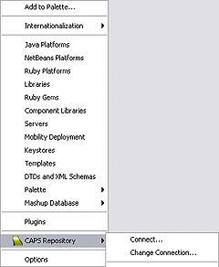
You can connect to a JavaCAPS Repository by selecting Tools > CAPS Repository > Connect, which displays the Connect to CAPS Repository dialog box. If you're already connected to a CAPS Repository, you can change Repositories by selecting Change Connection.
-
Specify or confirm the appropriate connection parameters and click Connect.
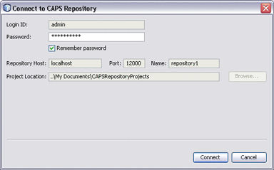
Note –The Project Location you specify is the directory you need to browse to in the following step. By default, this directory is c:\Documents and Settings\username\My Documents\CAPSRepositoryProjects.
The preceding figure shows the Login ID and Repository Host fields to be disabled, indicating that the connection parameters have been determined. You can redefine these parameters in any open Project, even if you are not currently connected to a CAPS Repository, by selecting Tools > CAPS Repository > Change Connection, which enables these fields for editing. If you do so, all other open Repository-based Projects will be closed automatically, since open Projects must come from a single Repository.
Creating a Repository-Based Project
The following procedure describes how to create a new top-level, Repository-based CAPS project in the NetBeans IDE. After creating your project, it will appear under the NetBeans Projects window.
 To Create a Top-level Repository-Based Project
-
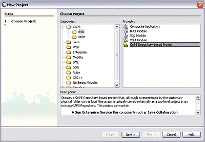
Click the New Project icon, or select File > New Project to initiate the New Project wizard.
-
In Step 1, select CAPS > ESB from the Categories column and CAPS Repository-Based Project from the Projects column, and click Next.
-
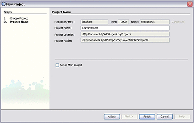
In Step 2, specify your Project Name and click Finish.
Opening a Repository-Based Project
The following procedure describes how to open an existing top-level, Repository-based CAPS project in the NetBeans IDE.
 To Open a Top-level Repository-Based Project
-
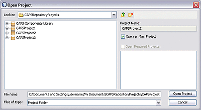
Click the Open Project icon, or select File > Open Project, which displays the Open Project dialog box.
-
Select one or more top-level projects from the displayed list and click Open Project. The project now appears as selected under the Projects window.

-
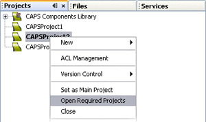
Select Open Required Projects from the context menu for the CAPS project to ensure that all other directly or indirectly referenced top-level CAPS projects are also opened under the Projects window.
Adding and Connecting Project Components
You can add most Project components to a Project by selecting the New > Component Type option from the Project context menu under the Projects window (a Scheduler is an exception). For those components appearing in the Connectivity Map Editor toolbar, you can simply drag the icon onto the Editor's canvas. Once you have finished editing the Connectivity Map, click the Generate Connectivity Map icon to add the components to the Project in the Repository.
Note –
Collaboration Definitions should be created before adding Collaborations, because of the complication of multiple targets.
Project Nesting
Projects can contain Subprojects, which in turn can contain other Subprojects. Primarily because of limitations in the user interface, the working limit for nesting Projects within other Projects is five levels (total), as shown in the following figure.
Figure 1 Project Nesting

Using the Connectivity Map Editor
When you create a new Connectivity Map in the Enterprise Explorer, the editor panel displays the Connectivity Map Editor, as shown in the following figure. To define your Project, you simply drag icons from the toolbar to the workspace, or canvas, to populate the Connectivity Map with the necessary components. You can also create objects under the Projects window using the Project context menu, and drag them onto the Connectivity Map canvas.
You subsequently link the components by dragging the cursor from the output arrowhead of one to the input arrowhead of the other. The cursor turns into a hand during this operation.
Figure 2 Connectivity Map Editor
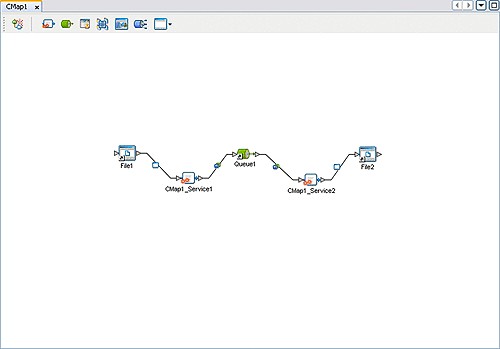
The drag-and-drop components include services, queues, topics, schedulers, and external applications. Additional components, such as Adapters and JMS Clients, are placed automatically when you link the components you have placed manually.
It is important to understand that the logical components appearing in the Connectivity Map are essentially placeholders that refer to the “actual” components that exist in the Repository and appear under the Projects window. Deleting a queue or topic in the Connectivity Map only affects the placeholder, not the object in the Repository. Deleting a queue or topic in the Repository, however, does delete its placeholder counterpart in the Connectivity Map. Renaming either the object or the placeholder automatically renames both.
When you link two components on a Connectivity Map, the NetBeans IDE places a connection icon on the link; the entity represented by the icon depends upon the type of components you are linking.
-
When you link an external application with a Collaboration, the NetBeans IDE automatically adds the appropriate adapter to the link. The adapter enables communication and movement of data between the external application and the other Project components. The adapter configuration specifies the logical connection properties for the link. See the individual adapter user guides for specific information.
-
When you link a Web Services External Application with a Collaboration, the NetBeans IDE automatically adds a Web Service External Application Connector to the link. This connector enables communication and movement of data between the web services application and the other Project components. The binding configuration specifies the logical connection properties for the link.
-
When you link a Service with a Message Destination (queue or topic), the NetBeans IDE adds a JMS Client connection to the link. The JMS Client configuration specifies the logical connection properties for the linked Service.
Linking Services and Destinations
After you have bound a Collaboration Definition to a service to create a Collaboration as described in Collaborations, you must link the Collaboration’s services to the inbound and outbound destinations.
 To Link Services and Destinations
-
Double-click the Collaboration (or other service) to display its binding box, as shown in the figure below.
-
Drag the output port of the source component to the Implemented Services pane.
-
Drag the services from the Invoked Services pane to their appropriate destinations
-
Close the Collaboration binding box and click Save.
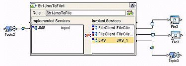
When there are multiple destinations, as in the example, the Connectivity Map Editor cannot resolve which output port connects to which destination. Because of this, you must first create the Collaboration Definition, and then make the connections by opening the Collaboration binding box and connecting the output ports for the individual services to their intended destinations.
Connection-related properties for the Collaboration or other service are configured in the adjoining JMS Client.
Adding and Setting Up Schedulers
Figure 3 Scheduler Icon
A Scheduler allows a service to be performed at a prescribed interval. It is treated as an external application, and must be deployed to a Scheduler External System in the runtime Environment.
As with other Project components, scheduler names can contain alphanumeric characters (letters and numbers), dashes, and underscores. The following special characters also can be used in scheduler names: <, >, &.
Note that:
-
Double-clicking the connector icon displays the Properties dialog for the associated scheduler.
-
Expanding the Scheduler node under the Projects window and selecting a sub-node (schedule type) also displays the Properties dialog for the scheduler.
-
Right-clicking the scheduler under the Projects window displays its context menu. See Project Component Context Menu for a list of menu options.
 To Add a Scheduler to the Project
-
If this is the first scheduler to be added to the Project, select the Scheduler icon from the External Application menu in the Connectivity Map Editor. This adds the icon to the editor's toolbar.
-
Drag the Scheduler icon from the toolbar onto the canvas and link it to the appropriate service. The connector icon appears as a red dot, indicating that it is not configured.
-
Configure the schedule and the time zone as described in the following procedures.
-
Click the Generate Connectivity Map icon to add the scheduler to the Project in the Repository.
 To Configure the Schedule
-
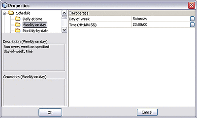
Select the appropriate schedule type, either from the Projects window or by accessing the Properties dialog. Selecting the type displays the properties for that type. For example, Weekly on day displays entry fields for the day of the week and the time.
-
Click in the value field to edit the value (a drop-down menu may be displayed).
Figure 4 Scheduler Properties Dialog: Schedule
 To Configure the Time Zone
-
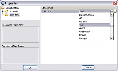
Select Time Zone to display the Time Zone entry field.
-
Click in the value field to display the menu, and select the time zone with which you want the Scheduler to be synchronized.
Figure 5 Scheduler Properties Dialog: Time Zone
Project Context Menu
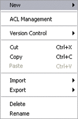
The different components available to you to incorporate into a Project are represented in the Project context menu. Top-level Projects and Subprojects have context menus similar to those shown in the following figures. Additional menu options may be shown, depending upon what additional products you have installed.
Figure 6 Project Context Menu
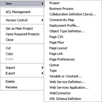
Figure 7 Subproject Context Menu
The various menu options are described in the following table.
Table 1 Project Context Menu Options
Project Component Context Menu
Project components have context menus such as that shown in the figure below.
Figure 8 Project Component Context Menu
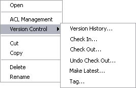
The various menu options are described in the following table.
Table 2 Project Component Context Menu Options
Connectivity Map Editor Toolbar
The Connectivity Map Editor toolbar contains the icons listed in the following table, plus additional icons representing adapter add-ons and other Java CAPS components that you may have installed.
Table 3 Connectivity Map Editor Toolbar Icons|
Icon |
Component |
Function |
|---|---|---|
|
Connectivity Map Generator |
Generates an object in the Repository corresponding to the graphical construct on the Connectivity Map canvas. |
|
|
Service |
A logical component that provides the framework for a process or Collaboration. See Collaborations. |
|
|
Queue |
A Message Destination that conforms to the point-to-point messaging paradigm, having one sender and one receiver. See Message Destinations. |
|
|
WLM Connector |
Connects a Business Process to the Worklist Manager for task assignment. |
|
|
Web Connector |
Connects a Business Process or Subprocess to another Business Process. |
|
|
Web Service Application |
Represents a Web Service Application (see Web Service Applications). |
|
|
Topic |
A Message Destination that conforms to the publish/subscribe messaging paradigm, having one sender (publisher) and multiple receivers (subscribers). See Message Destinations. |
|
|
External Applications |
Represents an application external to Java CAPS. Click the arrow beside the icon to view a list of specific applications to which you can connect. See External Applications. |
Project Component Overview
This topic briefly outlines the various components of a Repository-based Project.
Project Components
In a Repository-based Project, you specify the business logic for the specific implementation by defining the required Project components. For each of these components you specify logical properties, which are independent from the physical implementation. Projects are where you add and name message destinations, by dragging and dropping topics and queue icons onto the Connectivity Map canvas. See Connectivity Maps for additional information.
On links between message destinations and their subscribers and publishers, there is a JMS client properties icon. By double-clicking the JMS client properties icon in the Connectivity Map, you can configure the connection for such items as persistent or non-persistent delivery mode, XA, and concurrent processing.
After having added the components for message destinations, you create the Object Type Definitions (OTDs) and Collaboration Definitions. After defining the Collaboration Definitions, you then create the relationships between the components by associating Collaboration Definitions with services. This defines a service as a Collaboration, and binds the Collaboration to its Collaboration Definition.
External Applications
Generally speaking, external applications are the beginning and end points of the Project data path.
See:
Services
Services include Business Processes and Collaborations, which are the logical transformations to be performed on the data.
See:
Message Destinations
Message destinations (topics or queues) are internal storage and routing nodes within the Project.
See:
Connectors
Connectors provide links between Project components where JMS Clients are not appropriate, generally aside from the main data paths. They are used primarily when mapping Business Processes.
See:
Definitions
There are several Project components that are incorporated into other components as definitions. As such, they are not independently mappable and do not appear in the Connectivity Map Editor.
See:
Mapping Entities
Some additional Project components do not themselves appear in the data path, but rather affect those data path components in a global manner. Since they provide mapping information, they are not mappable in themselves, and do not appear in the Connectivity Map Editor.
See:
Business Processes
Figure 9 Business Process Icon
A business process is a collection of actions that take place in your company, revolving around a specific business practice. These business processes are modeled in Sun Business Process Manager, and then embodied as a service in a Repository-based Project. See Designing Business Processes in Sun Business Process Manager for information.
Collaborations
Figure 10 Java Collaboration Icon
A Collaboration represents a logical operation performed at run time between some combination of message destinations and external applications. These operations are often referred to as transformations. The nature of the operation is specified by a Collaboration Definition.
The Collaboration acts as a service having a publication or subscription relationship with each linked entity. The link is provided by a JMS Client connection, as described in Adding and Connecting Project Components. Dragging a Collaboration Definition from under the Projects window and dropping it onto the Service icon in the Connectivity Map defines the service as a Collaboration. The icon changes from a generic service to a Java Collaboration.
Note –
Any changes made to the names of the Collaborations should be done when the Collaboration is created. If the name is changed later, the Collaboration should be opened, regenerated if applicable, and saved again.
Message Destinations
A message destination is a container for stored data, and can follow either the JMS topic or JMS queue model.
-
A queue is a message destination that conforms to the point-to-point messaging paradigm.

-
A topic is a message destination that conforms to the publish-and-subscribe messaging paradigm.

You can add a message destination to a Project by selecting the New > Queue or New > Topic option from the Project context menu under the Projectswindow. You can also drag a Queue or Topic icon from the Connectivity Map toolbar onto the canvas. Clicking the Generate Connectivity Map icon then adds the component to the Project in the Repository. See also Connectivity Maps.
Right-clicking the queue or topic under the Projects window displays its context menu. See Project Component Context Menu for a list of menu options.
As with other Project components, message destination names can contain alphanumeric characters (letters and numbers), dashes, and underscores. The following special characters also can be used in message destination names: <, >, &, $, %. Blank spaces are not allowed.
External Applications
Figure 11 External Application Icon
External applications are logical representations of external software applications that are being integrated by the Java CAPS system. These are linked to a Service by means of an adapter. Clicking the drop-down arrow beside the external application icon in the Connectivity Map Editor presents a menu showing those applications corresponding to adapters that you have installed, plus the Scheduler. Selecting an individual external application adds that icon to the toolbar. The default set of external applications is shown in the following figure.
Figure 12 External Application Drop-Down Menu
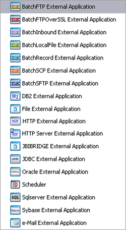
Right-clicking the External Application under the Projects window displays its context menu. See Project Component Context Menu for a list of menu options, and the individual adapter topics for additional information.
Web Service Applications
Figure 13 Web Service Application Icon
A Web Service Application is the logical representation of a web service that appears in a Repository-based Project.
If you are creating more than one Web Service Application for deployment in any given Environment, you must ensure that the respective servlet context properties have different values so that each application will have a different URL. See also “SOAP/HTTP Web Service External Systems” in Creating a Runtime Environment.
Right-clicking the Web Service Application under the Projects window displays its context menu. See Project Component Context Menu for a list of menu options.
Web Connectors
Figure 14 Web Connector Icon
A Web Connector connects a Business Process or Subprocess to another Business Process, for example to complete a feedback loop from a Subprocess back to the parent Business Process. For an example of its use in Project, see the Sun Business Process Manager Audit Processing Tutorial in Designing Business Processes in Sun Business Process Manager.
WLM Connectors
Figure 15 WLM Connector Icon
A WLM Connector connects a Business Process to the Worklist Manager for task assignment. For an example of its use in Project, see the Sun Business Process Manager Audit Processing Tutorial in Designing Business Processes in Sun Business Process Manager.
Collaboration Definitions
Figure 16 Collaboration Definition Icon
Collaboration Definitions define how data should be processed and routed between Project components, how databases should be queried in response to requests, and how APIs to one or more applications should be invoked. The external data formats that characterize the input and output data structures in a Collaboration Definition are described by Object Type Definitions (OTDs).
A Collaboration will typically receive a message containing the external representation of a particular OTD. It will use the unmarshal method of an instance of that OTD to parse the data and make it accessible though the hierarchical data structure. Then it will perform some operation— for example, copying parts of the data to another OTD instance. Finally, it will invoke the marshal method on the other OTD instance to render the contents of its data structure as a single, serialized data stream for further transport.
At run time, an OTD instance is accessed directly from Java, using accessors resembling JavaBeans. Each of the nodes comprising the hierarchy of the data structure has a set of properties with get and set methods.
A Java-based Collaboration Definition provides a single operation that can be invoked from a Business Process. You can create multiple methods in a Java-based Collaboration Definition, but the additional methods can only be invoked from within the Collaboration Definition.
Object Type Definitions
Figure 17 Object Type Definition Icon
The basic functionality of a Project is processing and routing messages, which it accomplishes by means of Collaborations. To operate on a message, the Collaboration needs a description of the message structure and format. This description is embodied in an Object Type Definition, or OTD, instances of which are incorporated into the Collaboration Definition.
A Collaboration will typically receive a message containing the external representation of a particular OTD. It will use the unmarshal method of an instance of that OTD to parse the data and make it accessible though the hierarchical data structure. Then it will perform some operation— for example, copying parts of the data to another OTD instance. Finally, it will invoke the marshal method on the other OTD instance to render the contents of its data structure as a single, serialized data stream for further transport.
In some cases, the OTD can be generated semi-automatically based on the external data source itself; in other cases, you must create the OTD using the tools provided in the NetBeans IDE.
Web Service Definitions
Figure 18 Web Service Definition Icon
Web Service Definitions, embodied as Web Service Definition Language (WSDL) files, can be used to invoke and operate web services on the Internet and/or to access and invoke remote applications and databases. WSDL files are used when you are building a web service.
A Web Service Definition, or WSD Object, can either be formed by importing an existing WSDL document or newly created using the Web Service Definition Editor. The minimum requirement for a WSD Object is that it represent an abstract WSDL document by containing (either directly or by import) one or more Operations and related messages. The WSD Object can also contain binding information.
XML Schema Definitions
Figure 19 XML Schema Definition Icon
XML schemas define the structure, content, data types, and elements allowed in an associated XML document. They also describe the semantic-processing instructions associated with the elements contained in the document. The XML schema is embodied in an XML Schema Definition (XSD) file, itself an XML document. XML schemas are used when you are building a web service based on a Java CAPS Collaboration Definition (Java).
Constants and Variables
Figure 20 Constant or Variable Icon
-
Project Constants
Constants are name-value pairs that are visible across the Project. Using a constant allows you to define the value once, and then refer to it from the various Project configurations, rather than having to redefine the value everywhere it is needed. For example, you might define a standard currency to be used globally throughout the system.
-
Project Variables
Variables function as placeholders, having values that are determined when you create a specific Deployment Profile. They can be either literals or Environmental constants.
Constants and variables are discussed further in Defining Constants and Variables.
Connectivity Maps
Figure 21 Connectivity Map Icon
A connectivity map is a graphical representation of your Project, containing the various logical components comprising the Project's data path and the links between them.
You can add a connectivity map to a Project by selecting the New > Connectivity Map option from the Project context menu in Projects window, which automatically opens the Connectivity Map Editor. The Connectivity Map Editor allows you to create much of your Project by simply dragging and dropping icons onto a Project canvas and then connecting them to form data paths. You then can configure the components by means of dialogs that are displayed by clicking on the component icons.
Right-clicking the connectivity map under the Projects window displays its context menu. See Project Component Context Menu for a list of menu options.
Deployment Profiles
Figure 22 Deployment Profile Icon
Deployment profiles define how specific instances of a Project are deployed to a particular Environment, following the model shown in the following figure. A deployment profile contains information about the assignment of services and message destinations to application and message servers. It also contains version information for all relevant objects in the Project.
Figure 23 Java CAPS Implementation Model

To create a new deployment profile, right-click on a Project under the Projects window to display its context menu. From the menu, select New > Deployment Profile. See Deploying Java CAPS Projects. To edit an existing deployment profile, select Open from its context menu. Either of these actions opens the Deployment Editor, where you can map Project components to the appropriate Environment components. See Project Component Context Menu for a list of menu options.
- © 2010, Oracle Corporation and/or its affiliates
