| Skip Navigation Links | |
| Exit Print View | |

|
Sun Storage F5100 Flash Array Topic Set |


Documentation, Support, and Training
Sun Storage F5100 Flash Array Overview
Obtaining the Chassis Serial Number
Choosing a Method for Diagnosing Faults
Diagnosing Faults With Sun StorageTek Common Array Manager Software
Diagnosing Faults With LEDs and Indicators
Energy Storage Module Indicators
Motherboard Assembly Troubleshooting
Preparing to Service the System
Performing an Antistatic Discharge
Customer-Replaceable and Field-Replaceable Components
Replacing an Energy Storage Module
Replacing the Motherboard Assembly
Replacing a Power Distribution Board
Replacing the Connector Board Assembly
Replacing the Energy Storage Backplane
Returning the System to Service
Install the Chassis to Maintenance Position
Return the System to the Fully Installed Position
The following table describes the controls and indicators on the left side of the front panel as shown in Front Panel (Left Side).
Table 2 Front Panel Controls and Indicators (Left Side)
|
Figure 9 Front Panel (Left Side)

Figure Legend
1 Locate LED (white)/button
2 Fault LED (amber)
3 OK LED (green)
4 On/Standby button
The following table describes the indicators on the right side of the front panel as shown in Front Panel (Right Side).
Table 3 Front Panel Controls and Indicators (Right Side)
|
Figure 10 Front Panel (Right Side)
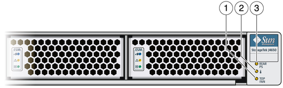
Figure Legend
1 Top Fan LED
2 Temperature Fault LED
3 Rear PS LED


|