JavaScript is required to for searching.
Skip Navigation Links
Exit Print View
Sun Netra 6000 Modular System HTML Document Collection
search filter icon
search icon

Document Information

Using This Documentation

Product Notes

Related Documentation

Feedback

Access to Oracle Support

Installation

Preparing Your Site Before the System Arrives

Modular System Overview

Supported Racks

Location Restrictions for DC Models

Aisle Clearance for Service

AC Power Requirements

Determining DC Power Requirements

Environmental Requirements

Airflow Requirements

Acoustic Noise Emissions

Weight and Size Specifications for Moving and Lifting

Preparing to Install the Modular System

Gather Required Tools and Equipment

Remove the Shipping Carton

Verify Shipment Contents

Note the CMM MAC Address

Installing the Chassis Into Your Rack

Depopulating the Chassis

Mounting the Chassis in a Rack

Repopulating the Chassis

Connecting To and Powering On the Modular System

Role of Oracle ILOM During Installation

Connectivity Choices

CMM IP Address Configuration

Connecting Data and Management Cables

Powering On the Modular System

Log Into the CMM Through the SER MGT Port

Configure the CMM NET MGT Port With a Static IP Address

Configure the IP Addresses Using Your DHCP Server

Identify the IP and MAC Addresses

Log Into the CMM Through the NET MGT Port

Change the CMM ILOM root Account Password

Installing Shipping Brackets on a Sun Rack 1000

Install Shipping Brackets

Remove Shipping Brackets

Remote Management (ILOM)

Understanding Oracle ILOM on the Modular System

Oracle ILOM Overview

Oracle ILOM 3.0 Features Specific to the Modular System

Configuring CMM ILOM

Logging Into and Out of CMM ILOM

Performing Common CMM ILOM Configuration Tasks

Viewing and Configuring IP and MAC Addresses

Managing the CMM Clock

Administering the Modular System (CMM ILOM)

Managing the Chassis Using the CLI

Accessing Server Modules (CMM ILOM)

Interpreting Sensors

Sensor Overview

Display Sensor Readings (CLI)

Chassis Sensors

Fan Sensors

Power Supply Sensors

NEM Sensors

Server Module Sensors

Identifying SNMP Trap and PET Event Messages

SNMP Traps

PET Event Messages

Service

Monitoring Faults

Understanding Fault Management

Monitoring Faults (LEDs)

Monitoring Faults (Oracle ILOM)

Preparing for Service

Component Types and Service Classifications

Differences Between Chassis Models and Their Replacement Components

Determine if a Chassis Is A90-B or A90-D (CLI)

Determine if a Chassis Is A90-B or A90-D (Web Interface)

Gather Required Tools

Prevent ESD Damage

Power Off the Server Modules and Storage Modules

Power Off Components in the Chassis

Removing Power From the Chassis

Removing the Chassis From the Rack

Replacing CRUs

Replacing a Power Supply

Remove a Power Supply (DC)

Install a Power Supply (DC)

Remove a Power Supply (AC)

Install a Power Supply (AC)

Replacing a Front Fan Module (AC)

Remove a Front Fan Module (AC)

Install a Front Fan Module (AC)

Replacing a Server or Storage Module

Remove a Server or Storage Module

Install a Server or Storage Module

Replacing the FIM

Remove a FIM

Install a FIM

Replacing a PCI EM

PCI EM Service Overview

Remove a PCI EM

Install a PCI EM

Replacing a NEM

Remove a NEM

Install a NEM

Replacing a Rear Fan Module

Remove a Rear Fan Module

Install a Rear Fan Module

Replacing the Fan Board

Remove the Fan Board

Install the Fan Board

Replacing the CMM

Remove the CMM

Install the CMM

CMM Reset Sequence

Replacing FRUs

Replacing the Midplane

Replacing an Internal Power Cable (AC)

Replacing the DC Input Unit

Replacing a DC Adapter Tray

Returning the Modular System to Operation

Reinstalling the Chassis Into a Rack

Applying Power to the Chassis

Verify Modular System Functionality

Glossary

Index

Remove a Server or Storage Module

  1. Initiate an orderly shutdown of the operating system.

    For instructions, refer to the documentation for your server module.
  2. Power down the server or storage module to standby power.
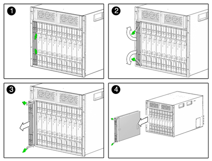
  3. Press the latches on the ejectors at the top and bottom of the server or storage module.
    image:Figure shows server or storage module being removed from chassis.
  4. Swing out both ejector latches simultaneously (raise the top ejector and lower the bottom ejector).
  5. Use the ejector latches to start pulling the server module out of its slot in the chassis.

    Caution

    Caution - Do not use the ejector latches to carry the server or storage module. The ejector latches should only be used to unseat the server or storage module from the chassis. The latches are not designed to support the weight of the server or storage module.


  6. Finish pulling the server or storage module out of the chassis, supporting the weight of the server or storage module from the bottom.
  7. Install a filler panel into the server or storage module slot if the server or storage module will be out of the chassis for longer than one minute.
  8. (If necessary) Install a new server or storage module.

    See Install a Server or Storage Module.

Related Information