| Skip Navigation Links | |
| Exit Print View | |

|
Sun Blade X3-2B (formerly Sun Blade X6270 M3) Service Manual |
Sun Blade X3-2B Model Name Change
Getting the Latest Firmware and Software
About the Chassis Monitoring Module (CMM)
Replaceable Server Module Components
Preparing the Sun Blade X3-2B for Service
Obtaining the Server Module Serial Number
Powering Off the Server Module
Performing ESD and Antistatic Prevention Measures
Remove the Server Module from the Sun Blade Chassis
Remove the Server Module Top Cover
Removing or Inserting Filler Panels
Servicing Sun Blade X3-2B Components
Servicing a Storage Drive (CRU)
Replace the System Battery (CRU)
Servicing USB Flash Drives (CRU)
Servicing a Fabric Expansion Module (CRU)
Servicing a RAID Expansion Module (CRU)
Servicing a Processor and Heat Sink Assembly (FRU)
Processor Fault Remind Circuit
Clear Server Module Processor Faults
Servicing the Motherboard Assembly (FRU)
Returning Sun Blade X3-2B to Operation
Install the Server Module Top Cover
Install the Sun Blade X3-2B in the Chassis
Troubleshooting the Sun Blade X3-2B
Diagnosing Server Module Hardware Faults
Troubleshooting Using LED Status Indicators
Using the DIMM and Processor Test Circuit
Troubleshooting Server Module Power States
Firmware and Software Troubleshooting
BIOS Power-On Self-Test (POST) Checkpoints
About POST Code Checkpoint Memory Testing
POST Code Checkpoint Reference
Getting Server Firmware and Software
Firmware and Software Access Options
Available Software Release Packages
Tip - To watch a video that shows how to remove and install a processor using the replacement tool, see CPU Replacement Overview Video.
 | Caution - Component damage. Handle processor socket pins with extreme care. Processor and socket pins are very fragile. A light touch can bend the processor socket pins and damage the board beyond repair. |
Before You Begin
Processor replacement tool model LGA2011 (color code: green) is required for this procedure.
 | Caution - Component damage. Use the correct processor replacement tool. Attempting to replace the processor using the incorrect tool could result in irreparable damage the processor or the motherboard. |
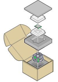
Leave the processor in the anti-static tray until it is ready to be installed.
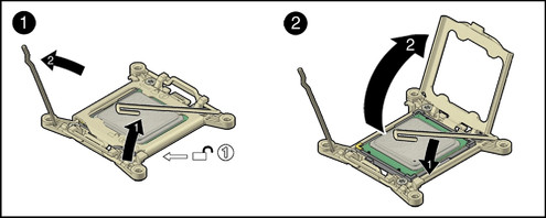
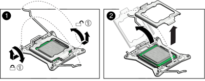
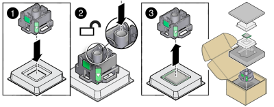
Properly position the tool over the processor socket and lower it into place over the processor socket. Ensure that the tool and processor key corners are aligned. To properly position the tool over the processor socket, rotate the tool until the green triangle on the side of the tool is facing the front of the server and it is over the left side of the processor socket when viewing the server from the front.
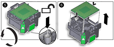
Press the release lever on the tool to release the center button and engage the processor. An audible click indicates that the processor is engaged.
Next Steps