Network Topology Overview
Network topology describes how networks fit together. Routers are the entities that connect networks to each other. A router is any machine that has two or more network interfaces and implements IP forwarding. However, the system cannot function as a router until properly configured, as described in Chapter 2, Configuring a System as a Router, in Configuring an Oracle Solaris 11.2 System as a Router or a Load Balancer .
Routers connect two or more networks to form larger internetworks. You must configure the routers to pass packets between two adjacent networks. The routers also should be able to pass packets to networks that lie beyond the adjacent networks by forwarding them to other routers that are connected to adjacent networks.
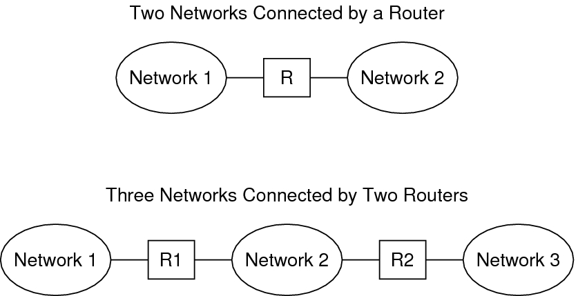
The following figure shows the basic parts of a network topology. The top portion of the illustration shows a simple configuration of two networks that are connected by a single router. The bottom portion of the illustration shows a configuration of three networks, interconnected by two routers. In the first example, Router R joins Network 1 and Network 2 into a larger internetwork. In the second example, Router R1 connects Networks 1 and 2. Router R2 connects Networks 2 and 3. The connections form a network that includes Networks 1, 2, and 3.
Figure 1-1 Basic Network Topology

In addition to joining networks into internetworks, routers route packets between networks that are based on the addresses of the destination network. As internetworks grow more complex, each router must make more and more decisions about the packet destinations.
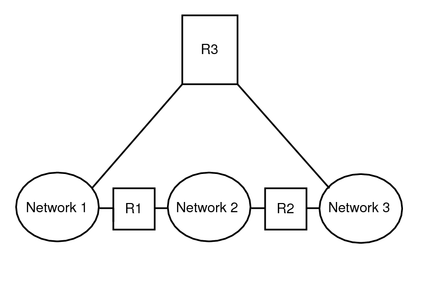
The following figure shows a more complex case. Router R3 directly connects networks 1 and 3. The redundancy improves reliability. If network 2 goes down, router R3 still provides a route between networks 1 and 3. You can interconnect many networks. However, the networks must use the same network protocols.
Figure 1-2 A Network Topology That Provides an Additional Path Between Networks

Routers are discussed in more detail in Planning for Routers on Your Network.