Configuring ILB for High Availability by Using the Half-NAT Topology
This section describes how to set up highly available ILB connections in a half-NAT topology. The scenario also uses two load balancers as primary and standby load balancers, respectively.
Note - The current implementation of ILB does not synchronize primary and standby load balancers. When the primary load balancer fails and the standby load balancer takes over, the existing connections fail. However, HA without synchronization is still valuable under circumstances when the primary load balancer fails.
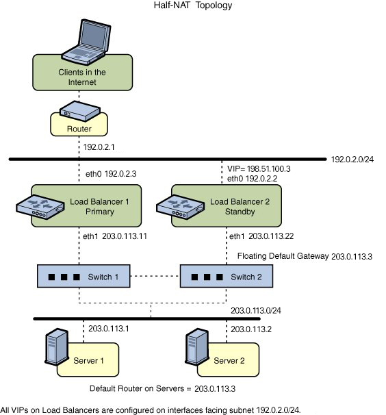
The following figure shows the configuration.
Figure 7 ILB for HA Configuration By Using Half-NAT Topology

How to Configure ILB for High-Availability by Using the Half-NAT Topology
Before You Begin
Ensure that your role has the appropriate rights profile to perform this procedure. See Using Rights Profiles to Perform Network Configuration.
-
Configure both the primary and standby load balancers.
$ ilbadm create servergroup -s server=203.0.113.1,203.0.113.2 sg1
$ ilbadm create-healthcheck -h hc-timeout=4,hc-count=3,hc-interval=6,hc-test=tcp hc1
$ ilbadm create-rule -ep -i vip=198.51.100.3,port=9001-9006,protocol=udp \
-m lbalg=roundrobin,type=HALF-NAT,pmask=24 -h hc-name=hc1,hc-port=9006 \

-t conn-drain=70,nat-timeout=70,persist-timeout=70 -o servergroup=sg1 rule1
-
Configure Load Balancer 1 to serve as the primary load balancer.
LB1$ dladm create-vnic -m vrrp -V 1 -A inet -l eth0 vnic1
LB1$ ipadm create-ip vnic1
LB1$ ipadm create-addr -d -a 198.51.100.3/24 vnic1
LB1$ vrrpadm create-router -V 1 -A inet -l eth0 -p 255 vrrp1
LB1$ dladm create-vnic -m vrrp -V 2 -A inet -l eth1 vnic2
LB1$ ipadm create-ip vnic2
LB1$ ipadm create-addr -d -a 203.0.113.3/24 vnic2
LB1$ vrrpadm create-router -V 2 -A inet -l eth1 -p 255 vrrp2
-
Configure Load Balancer 2 to serve as the standby load balancer.
LB2$ dladm create-vnic -m vrrp -V 1 -A inet -l eth0 vnic1
LB2$ ipadm create-ip vnic1
LB2$ ipadm create-addr -d -a 198.51.100.3/24 vnic1
LB2$ vrrpadm create-router -V 1 -A inet -l eth0 -p 100 vrrp1
LB2$ dladm create-vnic -m vrrp -V 2 -A inet -l eth1 vnic2
LB2$ ipadm create-ip vnic2
LB2$ ipadm create-addr -d -a 203.0.113.3/27 vnic2
LB2$ vrrpadm create-router -V 2 -A inet -l eth1 -p 100 vrrp2
-
Add the IP address for the floating default gateway to both
servers.
$ route add default 203.0.113.3
-
If Load Balancer 1 fails, Load Balancer 2 becomes the primary load balancer. Load balancer 2 then takes over address resolution for the VIP 198.51.100.3 and handles all the packets from clients with the destination IP address 198.51.100.3. Load balancer 2 also handles all the packets that are sent to the floating gateway address 203.0.113.3.
When Load Balancer 1 recovers, Load Balancer 2 returns to the standby mode.
-
If one or both of Load Balancer 1's interfaces fail, Load Balancer 2 takes over as primary load balancer. Load Balancer 2 then takes over address resolution for VIP 198.51.100.3 and handles all packets from clients with the destination IP address 198.51.100.3. Load balancer 2 also handles all the packets that are sent to the floating gateway address 203.0.113.3.
When both of Load Balancer 1's interfaces are healthy, Load Balancer 2 returns to standby mode.
This configuration provides protection against the following failure scenarios:
-