JavaScript is required to for searching.
Skip Navigation Links
Exit Print View
Oracle Switch ES1-24

Installation Guide

search filter icon
search icon

Document Information

Using This Documentation

Product Notes

Related Documentation

CLI Command Modes

Feedback

Support and Accessibility

Understanding the Installation

Installation Task Overview

Front Panel Components

Rear Panel Components

Confirming Specifications

Physical Specifications

Electrical Specifications

Environmental Specifications

Understanding Cabling

Understanding Management and Power Cabling

Management Connection Overview

NET MGT Port

SER MGT Port

Power Cord Specifications

Understanding Data Cabling

SFP+ Data Cable Overview

10GBASE-T Data Cable Overview

Data Cable Cautions

Data Cable Guidelines

Single-Switch Location Guidelines

Preparing for Installation

ESD Precautions

Tools Needed for Installation

Verify Switch Kit Contents

Verify Rack Rail Kit Contents

Assemble an SFP+ Data Cable

Route Cables

Installing the Switch

Assemble a Filler

Attach the Rails to the Switch

Attach Telco Adapters to the Rack Slides

Attach the Rack Slides to the Rack

Install the Switch Into the Rack

Attach Power Cords

Install the Air Duct and Front Support

Attach Data and Management Cables

Prepare the Front Support and Small Air Duct

Powering On the Switch

Power On the Switch

Oracle ILOM Overview

Verify the DHCP-Assigned IP Address and Host Name

Configure Network Management From the CLI (SER MGT)

Log Into the Oracle ILOM Web (NET MGT)

Log Into the Oracle ILOM CLI (NET MGT)

Log Into the Oracle ILOM CLI (SER MGT)

Glossary

Index

Attach Data and Management Cables


Note - This procedure primarily describes attaching data cables, however the procedure is the same for the management cables.

  1. Identify the prerequisite and subsequent installation tasks that you must perform in conjunction with this procedure.

    See Installation Task Overview.

  2. Consider your next step.
    • If you are installing the switch with the data connectors on the hot aisle, go to Step 3.

    • If you are installing the switch with the data connectors on the cold aisle, go to Step 4.

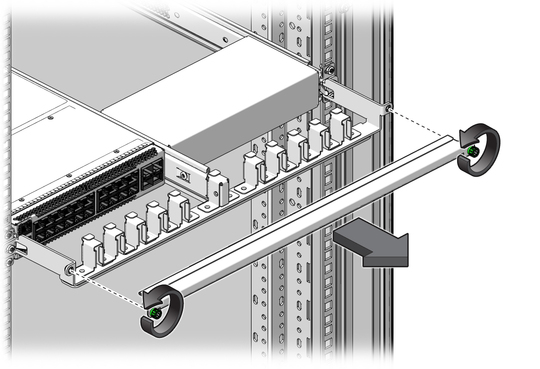
  3. Loosen the green captive thumbscrews and remove the cover from the CMA.
    image:Figure shows removing the CMA cover.
  4. Identify where the cable installs.

    See Front Panel Components.

  5. If installed, remove the protective dust cap on the cable.
  6. Inspect the cable connector.

    The shell should not be bent and should be parallel to the inner boards. If the connector is bent or damaged, use a different cable.

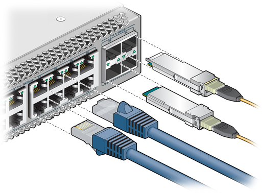
  7. Align the cable to the receptacle according to the connector location.
    • Upper row - Connector tab is up.

    • Lower row - Connector tab is down.


    image:Figure shows orientation of connectors.
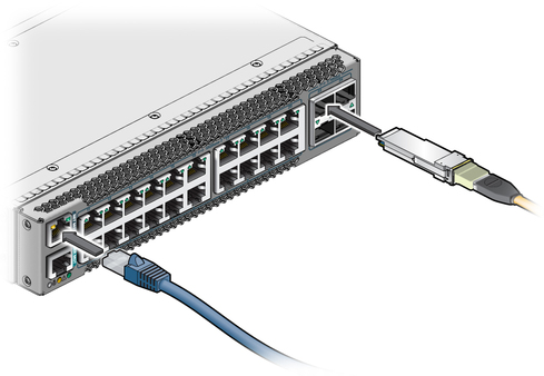
  8. Hold the transceiver or connector, and slide it into the opening.
    image:Figure shows sliding the switch into the rack.
  9. Applying even pressure to both sides of the cable, push the cable in until it is firmly seated and clicks in the slot.
  10. Repeat Step 4 through Step 9 for all connectors.
  11. Consider your next step.
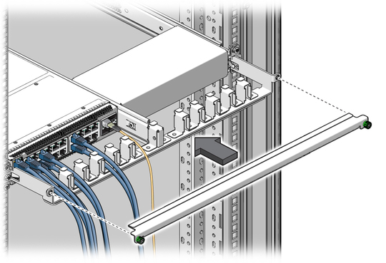
  12. Place the cable into the open slot in the CMA.

    Four cables fit into each slot in the CMA.
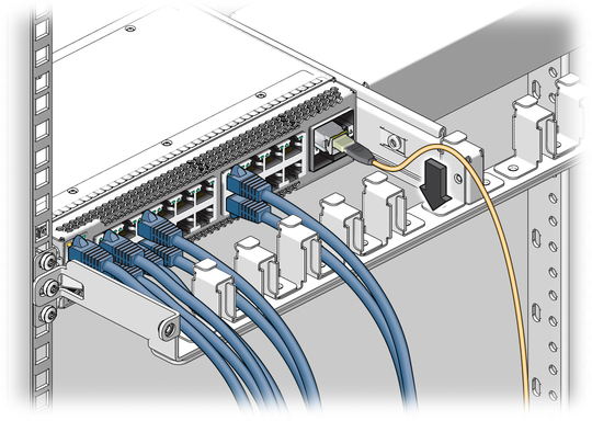

    image:Figure shows the cables being laid into the CMA.
  13. Replace the CMA cover, and tighten the green captive thumbscrews.
    image:Figure shows the cover being put on the cable management bracket
  14. Power on the switch.

    See Power On the Switch.

Related Information