Setting Up an EVS Virtual Tenant Network
A virtual switch is either a software or hardware entity that facilitates inter-virtual machine (VM) communication by looping the inter-VM traffic within a physical machine rather than sending it out on the wire.
EVS enables you to explicitly create virtual switches that span one or more nodes (physical machines), which further virtualizes your network. The virtual switch that you create represents an isolated L2 segment that uses either VLANs or VXLANs to implement the isolation.
For more information about the EVS architecture, see EVS Components in Managing Network Virtualization and Network Resources in Oracle Solaris 11.3.
This scenario's overall objective is to set up and deploy an EVS virtual tenant network. The primary objective is to create an elastic virtual switch (vswitch) that connects two compute nodes so that both nodes are part of the same L2 segment and can communicate with each other.
-
Deploy a virtual tenant network with two zones that are connected to the network through anet VNICs.
-
Deploy the VNICs on a private cloud infrastructure that has two compute nodes.
-
Use a VLAN L2 infrastructure to instantiate the private virtual tenant network.
The individual objectives for this scenario are as follows:
Note - Other L2 technologies such as VXLANs are also supported. For more information, see Use Case: Configuring an Elastic Virtual Switch for a Tenant in Managing Network Virtualization and Network Resources in Oracle Solaris 11.3.
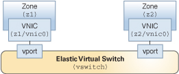
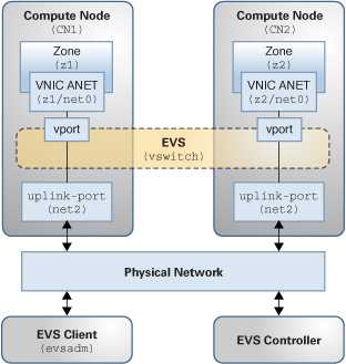
The following figures represent the virtual and physical components of the elastic virtual switch configuration that is used in this scenario.
Figure 4 Virtual Components of an EVS Switch Configuration

Figure 5 Physical Components of an EVS Switch Configuration

-
Two compute nodes (CN1 and CN2).
-
Two zones (z1 and z2) that are configured on CN1 and CN2, respectively.
-
The two zones (z1 and z2) are configured with a VNIC anet resource on each zone.
-
One node that acts as the EVS controller.
-
One node that acts as the EVS client.
Note - The EVS controller and the EVS client can be located on the same host. -
Two uplink-ports (net2) that specify the datalink to be used for the VLANs.
The following setup uses four network nodes with the following configuration:
Perform Preliminary Tasks Prior to Creating an EVS Virtual Tenant Network
-
Plan the EVS virtual tenant network deployment by doing the following:
-
Select the two compute nodes.
-
Designate a node to act as the controller.
-
Designate a node to act as the EVS client.
Note - The client and controller nodes can be on the same host. -
Select the VLAN ID range to be used for tenant traffic.
-
Decide which datalink to use for tenant traffic on each compute node.
-
-
Install the base EVS package (pkg:/service/network/evs) on every node.
-
Install the pkg:/system/management/rad/module/rad-evs-controller package on the controller node.
-
Configure each of the nodes so that Remote Administration Daemon (RAD) invocations are enabled.
-
On every node, configure EVS to point to the controller.
-
From the EVS client node, configure the controller properties.
-
From the EVS client node, verify the controller configuration.
The following one-time setup tasks are described:
Prior to setting up an EVS switch, you need to install the necessary software packages. You install these packages on each EVS node separately.
Install the base EVS package (pkg:/service/network/evs) on every node (client, controller, and the compute nodes) as follows:
# pkg install evs
Install the pkg:/system/management/rad/module/rad-evs-controller package on the node that is designated as the EVS controller as follows:
# pkg install rad-evs-controller
After installing the mandatory EVS packages and prior to configuring and setting properties for the EVS controller, you must configure all of the nodes so that RAD invocations between each node can take place. For detailed instructions, see Security Requirements for Using EVS in Managing Network Virtualization and Network Resources in Oracle Solaris 11.3.
Example 11 Configuring and Setting Properties for the EVS ControllerThe EVS controller provides the resources that are associated with creating and managing elastic virtual switches. You set properties for the controller that specify the necessary information for implementing L2 segments across physical nodes. See EVS Controller in Managing Network Virtualization and Network Resources in Oracle Solaris 11.3.
Configure each compute node so that it points to the EVS controller. This scenario uses two compute nodes, so you will need to run the following command on each of the compute nodes:
# evsadm set-prop -p controller=CONTROLLER
From the client node, configure the EVS controller properties.
-
Set the L2 topology.
# evsadm set-controlprop -p l2-type=vlan
-
Set the VLAN range.
# evsadm set-controlprop -p vlan-range=200-300
-
Specify the uplink-port (datalinks) that are used for the VLAN.
# evsadm set-controlprop -p uplink-port=net2
-
Verify the controller configuration on the EVS client.
# evsadm show-controlprop -p l2-type,vlan-range,uplink-port
NAME              VALUE        DEFAULT      HOST
l2-type           vlan         vlan         --
vlan-range        200-300      --           --
uplink-port       net2         --           --
Create an EVS Virtual Tenant Network (vswitch)
The following examples show how you would set up and configure an EVS virtual tenant network named vswitch. Pay particular attention to where you perform each task.
-
From the client node, set up a virtual switch.
-
On each compute node, create a zone and then connect the zone to the virtual switch.
-
From the client node, display the EVS configuration.
The following configuration tasks are described:
For an overview of the EVS feature, see Chapter 5, About Elastic Virtual Switches in Managing Network Virtualization and Network Resources in Oracle Solaris 11.3.
Example 12 Setting Up an EVS SwitchThe following example shows how you would set up an EVS virtual tenant network. You perform this task from the client node.
First, create the EVS switch, named vswitch in this example, as follows:
# evsadm create-evs vswitch
Add the IPnet information to the EVS switch and verify the configuration.
# evsadm add-ipnet -p subnet=192.0.2.0/24 vswitch/ipnet
# evsadm show-ipnet

NAME             TENANT     SUBNET          DEFROUTER    AVAILRANGE
vswitch/ipnet    sys-global 192.0.2.0/24 192.0.2.1 192.0.2.2-192.0.2.254
Verify that the EVS switch was successfully created.
# evsadm
NAME         TENANT       STATUS     VNIC      IP               HOST
vswitch      sys-global    --         --       vswitch_ipnet    --
Check the VLAN ID that is associated with the virtual switch.
# evsadm show-evs -L
EVS       TENANT      VID      VNI
vswitch   sys-global  200      --
Example 13 Creating and Connecting a Zone to an EVS Switch
The following example describes how you would create a zone on each tenant, and then connect the zone to the virtual switch.
On each tenant, configure a zone with an anet VNIC resource as follows:
# zonecfg -z z1
zonecfg:z1> create
.
.
.
zonecfg:z1> add anet
zonecfg:z1:anet> set evs=vswitch
zonecfg:z1:anet> end
zonecfg:z1> commit
zonecfg:z1> exit
For more information, see Creating a VNIC anet Resource for an Elastic Virtual Switch in Managing Network Virtualization and Network Resources in Oracle Solaris 11.3.
For information about setting anet resource properties that pertain to an EVS switch, see Resource Types and Properties in Oracle Solaris Zones Configuration Resources.
Boot the zone.
# zoneadm -z z1 boot
Verify that the VNIC was created and is connected to the virtual switch.
# dladm show-vnic -c
LINK         TENANT        EVS       VPORT        OVER    MACADDRESS        VIDS
z1/net0      sys-global    vswitch   sys-vport0   net2    2:8:20:1a:c1:e4   200
From within the zone, verify that the IP address has been assigned.
# zlogin z1 ipadm
NAME      CLASS/TYPE   STATE      UNDER    ADDR
lo0       loopback     ok         --       --
lo0/v4    static       ok         --       127.0.0.1/8
lo0/v6    static       ok         --       ::1/128
net0      ip           ok         --       --
net0/v4   inherited    ok         --       192.0.2.3/24
From the client node, display the EVS configuration.
# evsadm
NAME     TENANT     STATUS     VNIC     IP     HOST
vswitch   sys-global -- --     vswitch_ipnet
EVS provides a rich set of functionality that is not fully described in this scenario. For additional tasks and use cases, see Chapter 6, Administering Elastic Virtual Switches in Managing Network Virtualization and Network Resources in Oracle Solaris 11.3.