When replacing a component, you must know its part number and whether it is hot serviceable. Having that information helps you to order the correct replacement component and to determine whether you can replace the component yourself. To locate part numbers, open Oracle System Handbook (https://support.oracle.com/handbook_private/index.html). The part numbers are listed in the Oracle FS1 Flash Storage System components list.
The Controller is a two rack-unit (2U) server and consists of several replaceable components. Many Controller components are customer replaceable (CRUs), while others are field replaceable units (FRUs) that require Oracle Customer Support to perform the replacement. Also, some components are hot-serviceable, meaning that they can be replaced, while the Controller is powered on. Some of the Controller component replacement procedures require the Controller to be powered off and/or removed from the rack. The following table provides a summary of the Controller FRUs and CRUs.
Some FRUs and CRUs can be accessed from the front or back of the Controller. For replacing other FRUs and CRUs, you must open the top cover of the Controller. The following figure shows the components located at the back of the Controller.
| Controller component | Type | Hot serviceable |
|---|---|---|
| 4 GB NVDIMM | FRU | No |
| 16 GB DIMM module | CRU | No |
| Air filter | CRU | Yes |
| Central processing unit (CPU) | FRU | No |
| Disk backplane | FRU | No |
| Energy storage module (ESM) | CRU | No |
| Fan module | CRU | No |
| Controller identification display (CUID) | FRU | No |
| HBA [Sun Storage: 16 Gb/s Fibre Channel (FC) PCI-e] | CRU | No |
| HBA [Sun Storage: 16 Gb/s FC optics] | CRU | No |
| HBA [Sun Storage: 10 Gb/s FCoE optics][iSCSI] | CRU | No |
| HBA [dual-port 10 GbE PCIe 2.0 Copper and Fiber SFP+] | CRU | No |
| HBA [8 Gb/s Dual-Port FC PCI-e] | CRU | No |
| Heat sink | FRU | No |
| LED alarm board assembly | FRU | No |
| Motherboard cable kit | FRU | No |
| Power distribution board (PDB) | FRU | No |
| Power supply | CRU | Yes |
| Rail kit assembly | CRU | No |
| Riser board assembly | CRU | No |
| SAS HBA (PCIe-3, 6 Gb/s, 4x4 port) | CRU | No |
Figure 1 Controller back view
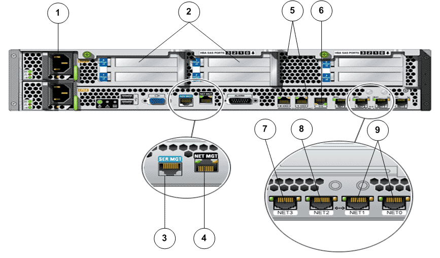
- Legend
1 Power supplies 6 Network port to opposite Controller 2 HBA slots 7 Network port to Pilot PMI 3 Server management port 8 Network port to opposite Controller PMI 4 Network management port 9 Ports for NAS host connection 5 Serial link port to opposite Controller
The following figure shows the front of the Controller with the air filter.
Figure 2 Controller front view with the air filter
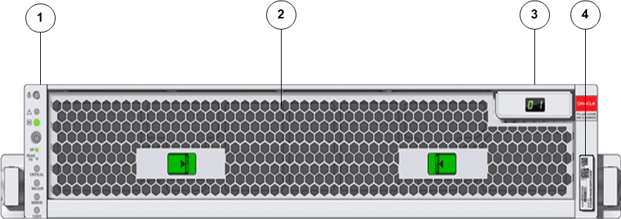
- Legend
1 LED alarm board assembly 3 Controller identification display 2 Air filter 4 Controller RFID tag
The following figure shows the front of the Controller without the air filter.
Figure 3 Controller front view without the air filter
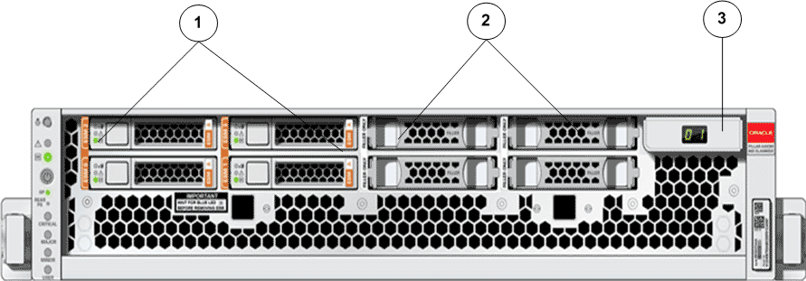
- Legend
1 ESM modules (0,1,2,3) 2 Filler panels 3 Controller Unit Identification Display (CUID)
The following figure shows all the replaceable components of the Controller.
Figure 4 Exploded view of Controller replaceable components 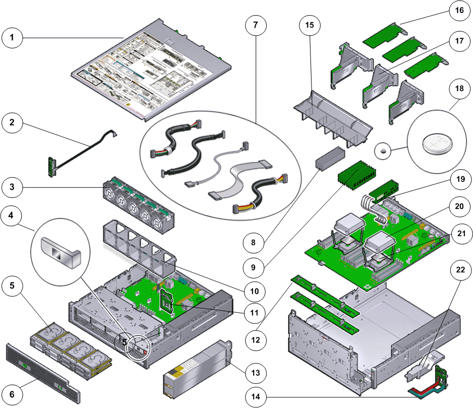
- Legend
1 Top cover (with service label) 9 DIMMs 17 Riser 2 LED assembly 10 Fan compartment 18 Battery 3 Fan modules 11 PDB Risers 19 NV-DIMM 4 CUID 12 ESM backplane boards 20 Heat sink 5 Energy storage modules (ESMs) 13 Power supply 21 CPU 6 Air filter 14 PDB Duct 22 PDB cover 7 Motherboard cable kit 15 Air duct 8 Filler panels for DIMM slots 16 HBA