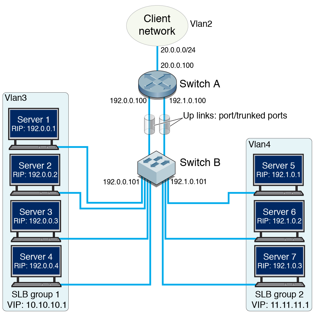
Multiple-SLB-Group Configuration
This example shows the SLB configuration with servers configured as multiple SLB groups. Servers and clients are at multiple VLANs, and the servers are indirectly attached to the switch.

|
In this sample configuration, the switches perform as follows:
Switch A:
Runs SLB.
Attached to the client network using switch ports extreme-ethernet 0/1-4.
Connected to switch B through two uplink ports extreme-ethernet 0/9-10. Port extreme-ethernet 0/9 carries VLAN 3 traffic, port extreme-ethernet 0/10 carries VLAN 4 traffic.
Switch B:
Directly connects to the servers.
Connects to switch A through two uplink ports extreme-ethernet 0/11-12. Port extreme-ethernet 0/11 carries VLAN 3 traffic, port extreme-ethernet 0/12 carries VLAN 4 traffic.
Servers in SLB group1 are connected to switch ports extreme-ethernet 0/15-18.
Servers in SLB group 2 are connected to switch ports extreme-ethernet 0/19-21.