When replacing a component, you must know its part number and whether it is hot serviceable. Having that information helps you to order the correct replacement component and to determine whether you can replace the component yourself. To locate a part number for the Pilot, open Oracle System Handbook (https://support.oracle.com/handbook_private/index.html) and go to the Oracle FS1 Flash Storage System components list. Part numbers are listed in the components list.
The Pilot is a one rack-unit (1U) server and consists of several replaceable components. Many Pilot components are customer replaceable (CRUs), while others are field replaceable units (FRUs) that require Oracle Customer Support to perform the replacement. Also, some components are hot-serviceable, meaning that they can be replaced, while the Pilot is powered on. The following table provides a summary of the Pilot FRUs and CRUs.
| Pilot component | Type | Hot-serviceable |
|---|---|---|
| Battery | CRU | No |
| USB Oracle System Assistant (OSA) flash drive | CRU | No |
| Disk backplane | FRU | No |
| 8 GB DIMM module | CRU | No |
| Cable kit | FRU | No |
| CPU | FRU | No |
| 300 GB SAS HDD | FRU | No |
| Fan module | CRU | No Note: GM support is required to ensure that failover has occurred.
|
| Riser | CRU | No |
| SAS HBA [6 Gb/s] | CRU | No |
| Heat sink | FRU | No |
| Power supply | CRU | Yes |
Figure 1: Pilot back view
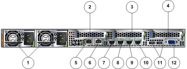
- Legend
1 Power supplies 7 Ethernet port (ETH-0) labeled as NET-3 2 PCIe card slot 1 8 Ethernet port (ETH-1) labeled as NET-2 3 PCIe card slot 2 9 Ethernet port (ETH-2) labeled as NET-1 4 PCIe card slot 3 and PCIe 4 slot (PCIe 4 slot is for the internal SAS HBA card and is not visible from the back of the Pilot) 10 Ethernet port (ETH-3) labeled as NET-0 5 ILOM SP network management port (labeled as NET MGT port) 11 USB connectors 6 Serial management port (labeled as SRMGT port) 12 Video connector
Figure 2: Pilot front view
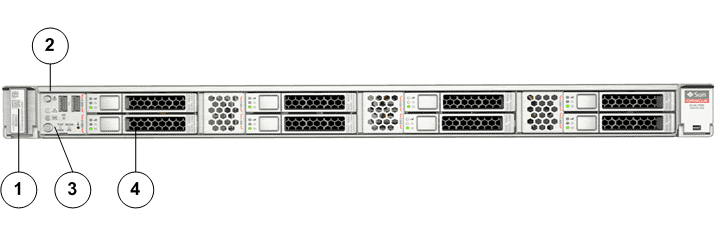
- Legend
1 Product serial number RFID tag 3 Front indicator module (FIM) 2 Power button 4 Pilot boot drive
Figure 3: Exploded view of Pilot replaceable components
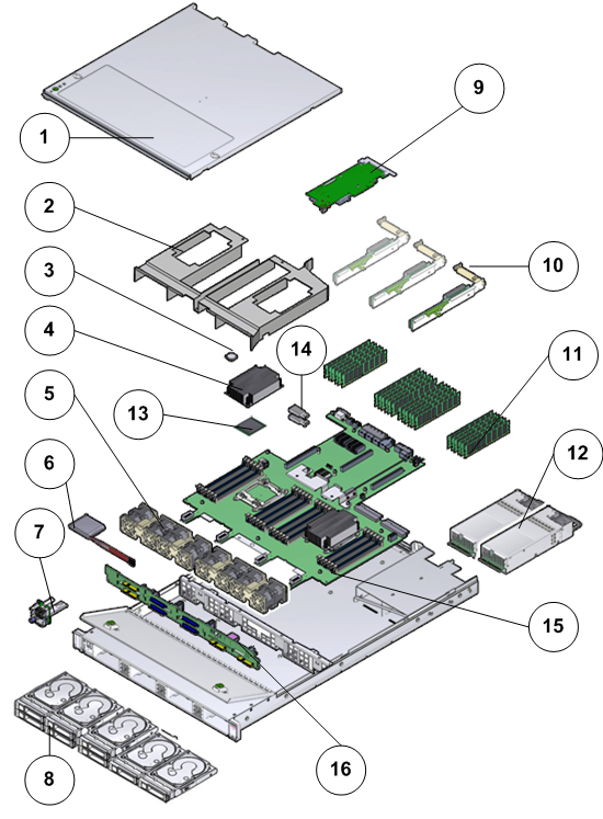
- Legend
1. Pilot top cover 9 SAS HBA 2 Air baffle 10 Risers 3 Battery 11 DIMMs 4 Heat sink 12 Power supplies 5 Fan modules 13 CPU 6 Front Indicator Module (FIM) 14 USB OSA flash drive 7 Energy Storage Module (ESM) for Oracle 12 Gb/s SAS PCIe RAID HBA that goes into PCIe slot 4 15 Motherboard 8 SAS HDDs 16 Disk backplane boards