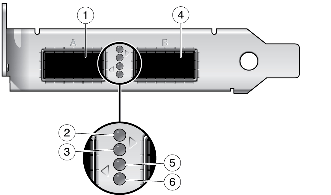
Front Panel Connectors and LEDs
On the front panel between the two ports, four LEDs signal the port speed, state, and activity. This figure and this table explains the meaning of the LEDs for port 0 (A) and port 1 (B). Port 0 accepts a QSFP+ optical transceiver, which can be purchased separately or included with your adapter.
For the 4x10GbE mode, only port 0(A) can be configured. If you use a splitter cable, port 0 can act as four ports. If a splitter cable that has four cables on the other end is used, and if all four splitter cables are connected to SFP+ ports of a client, then all four LEDs will be green. If there is activity on all four ports, then all four LEDs will blink. If any of the four cables are not connected, then the corresponding LED will be off. The Splitter cable has label 1, 2, 3, 4 (fiber splitter) or a, b, c, d (copper splitter) corresponding to port LED callout numbers 2, 3, 5, and 6.
For the 2x2x10GbE mode, both port 0 (A) and port 1 (B) are active. LED callout numbers 2 and 3 correspond to port 0 (A). LED callout numbers 5 and 6 correspond to port 1 (B).

|
Note - With 4x10GbE, the LED corresponding to the connected cable is green and that LED blinks with activity on that port.