Replace the Mainboard
The mainboard is a field replaceable unit that customers can order from Oracle. Perform these steps during a scheduled downtime when the system is not processing live traffic and after the system has been gracefully shut down from the ACLI.
See the "Cluster Member Graceful Shutdown" section in the Configuration Guide for how to gracefully shut down your system.
Remove the Mainboard
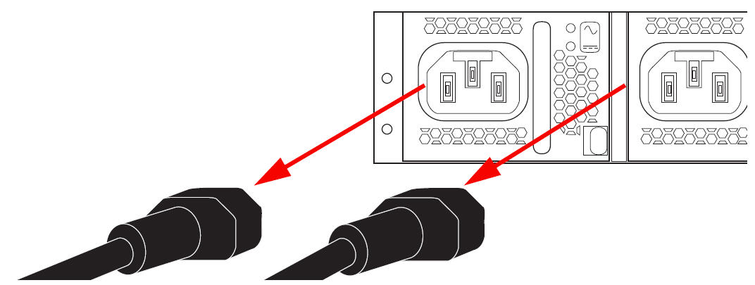
- After shutting down the system, disconnect the Acme Packet 6400 from both power supplies.
Figure 5-3 Removing the Power Cords
- Disconnect all cables and the ground wire from the rear of the system.
- Remove the Acme Packet 6400 from the rack and place it carefully on a table.
- Remove the system cover.
See Remove the Cover.
- Remove the power supplies from the chassis.
- Remove the four fan modules.
See Remove a Fan Module.
- Disconnect the front indicator module (FIM) cable from the
mainboard.
See Remove the FIM for instructions on how to disconnect the FIM.
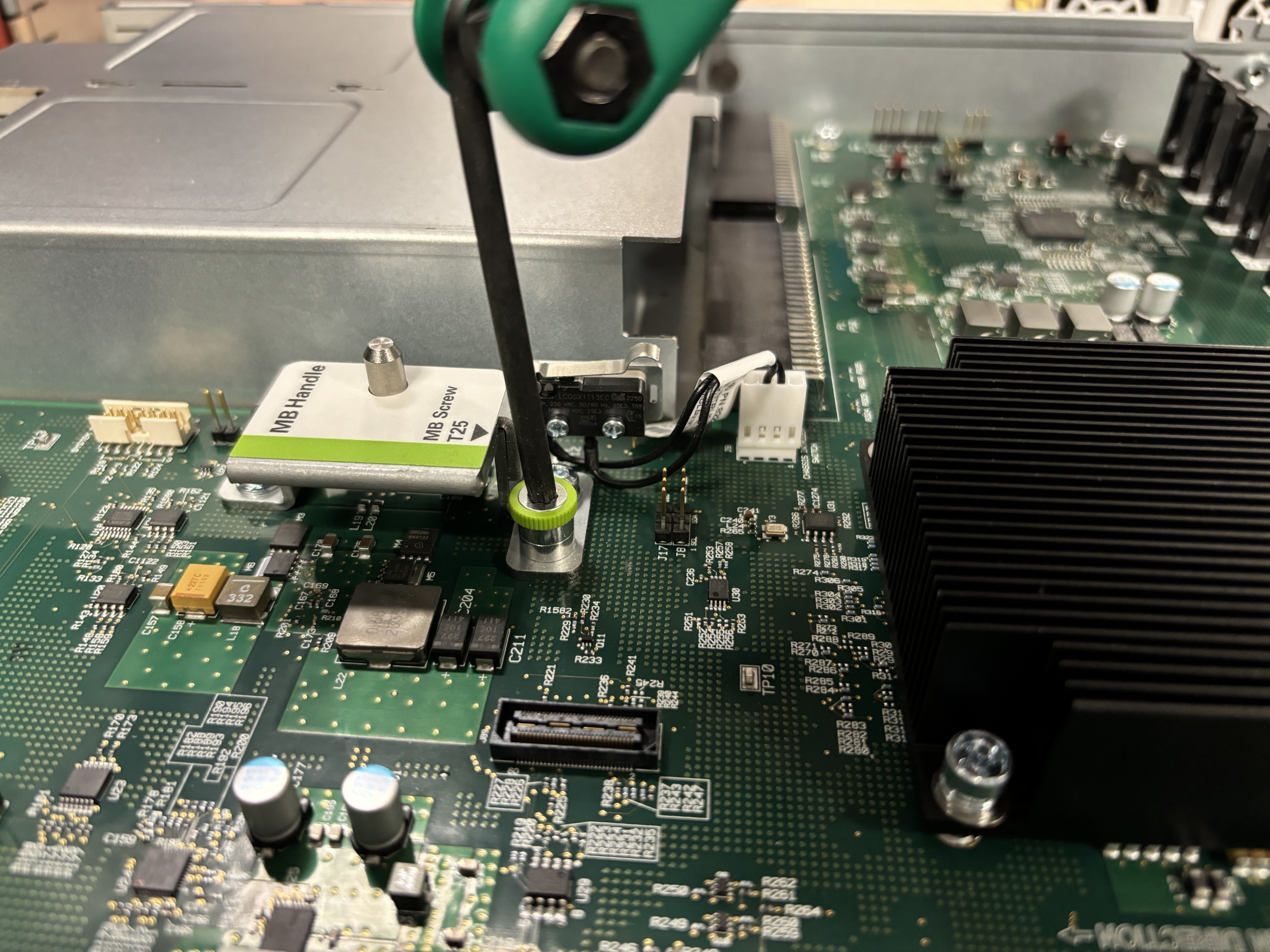
- Use a Torx T25 screwdriver to loosen the green captive screw next
to the mainboard handle.
- Grip the mainboard by the mainboard handle and the secondary
mainboard handle.
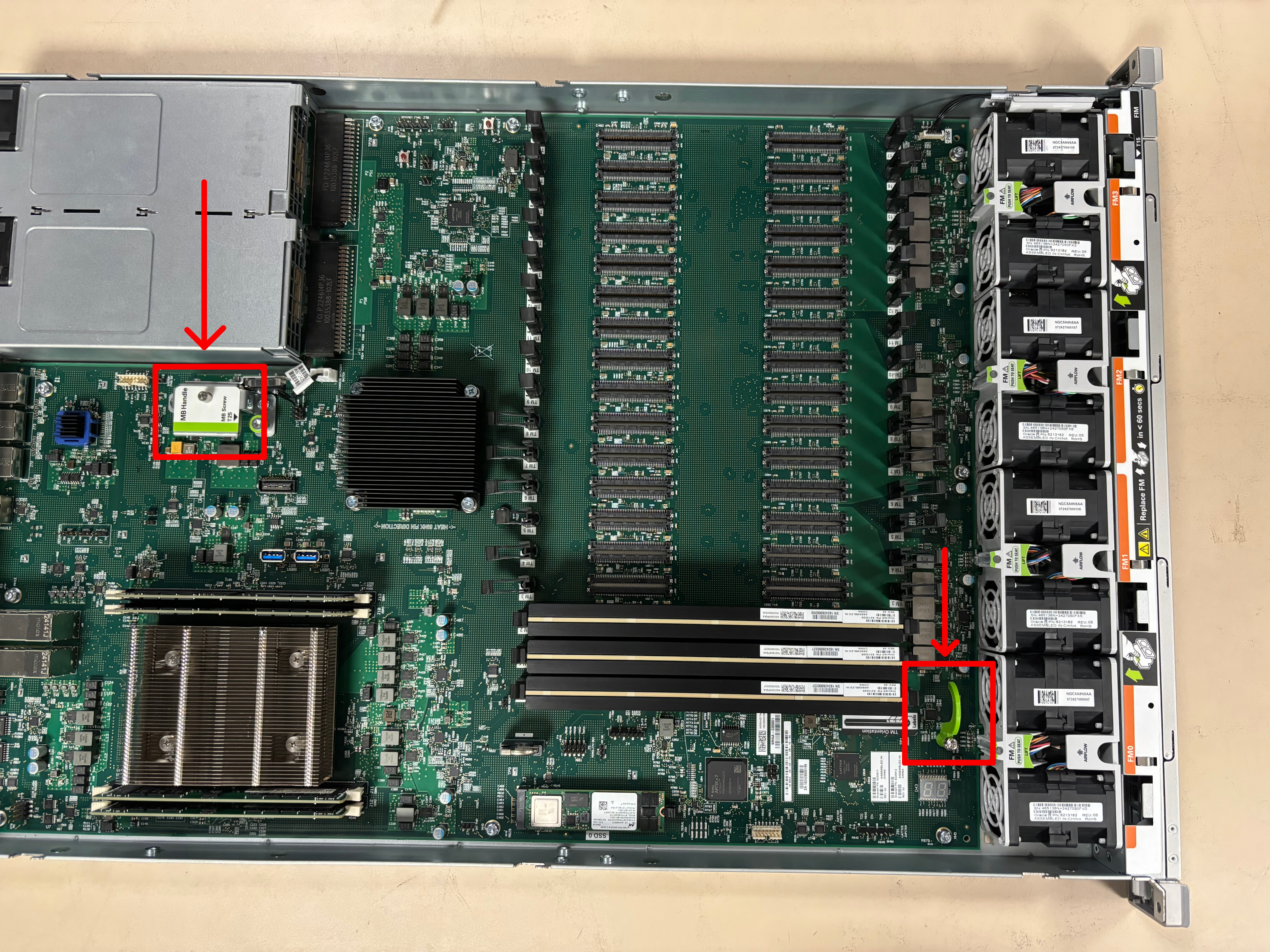
- Slide the mainboard toward the front until it stops.
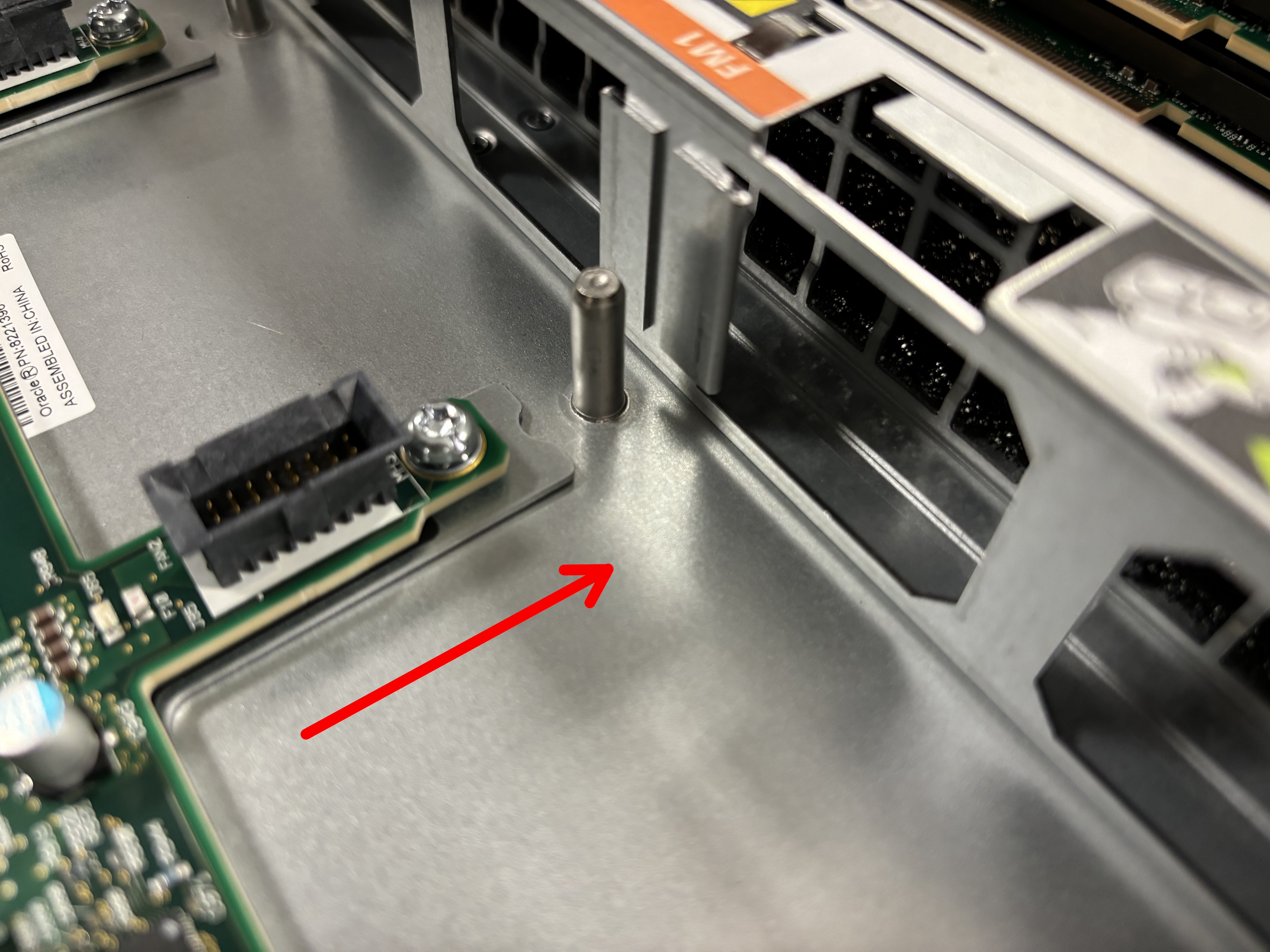
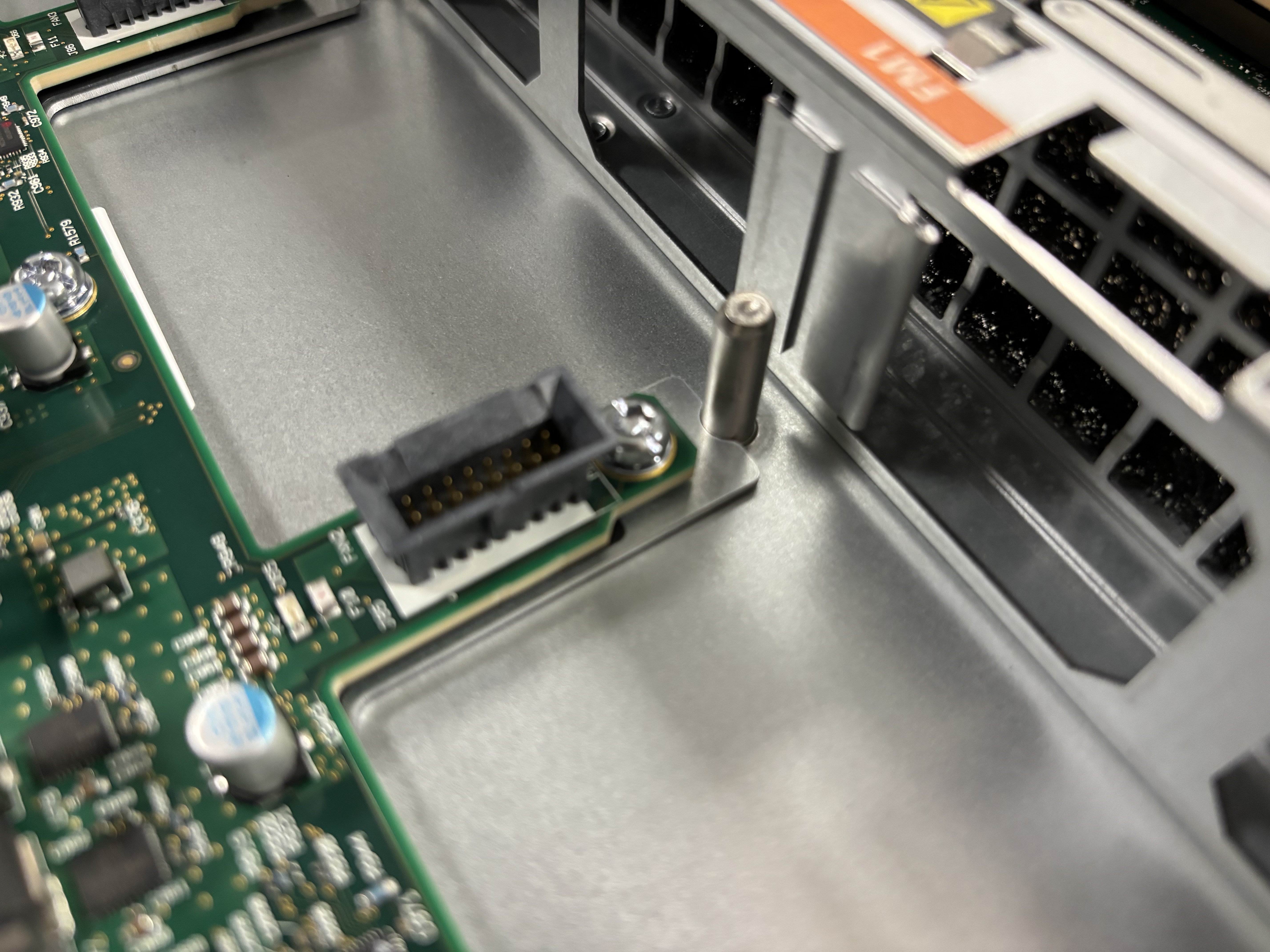
- Lift out the mainboard.
Install the Replacement Mainboard
- Remove the replacement mainboard from its packaging.
- Grip the mainboard by the mainboard handle and the secondary
mainboard handle.
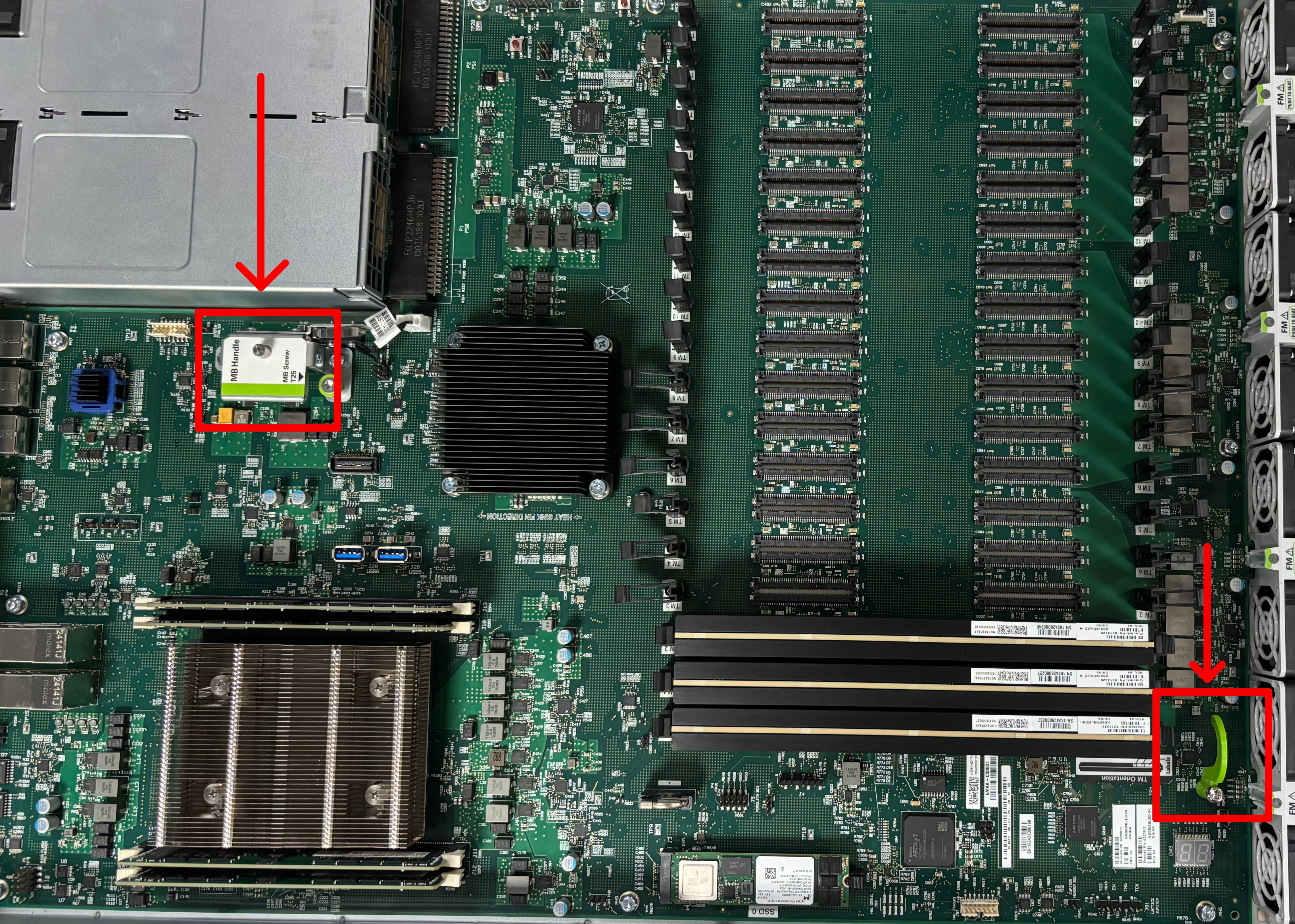
- Lower the mainboard into the chassis and align the four metal tabs
or wings on the mainboard with the four studs in the chassis.

- Lower the mainboard down to be flush with the chassis floor.
- Slide the mainboard toward the rear until it stops.
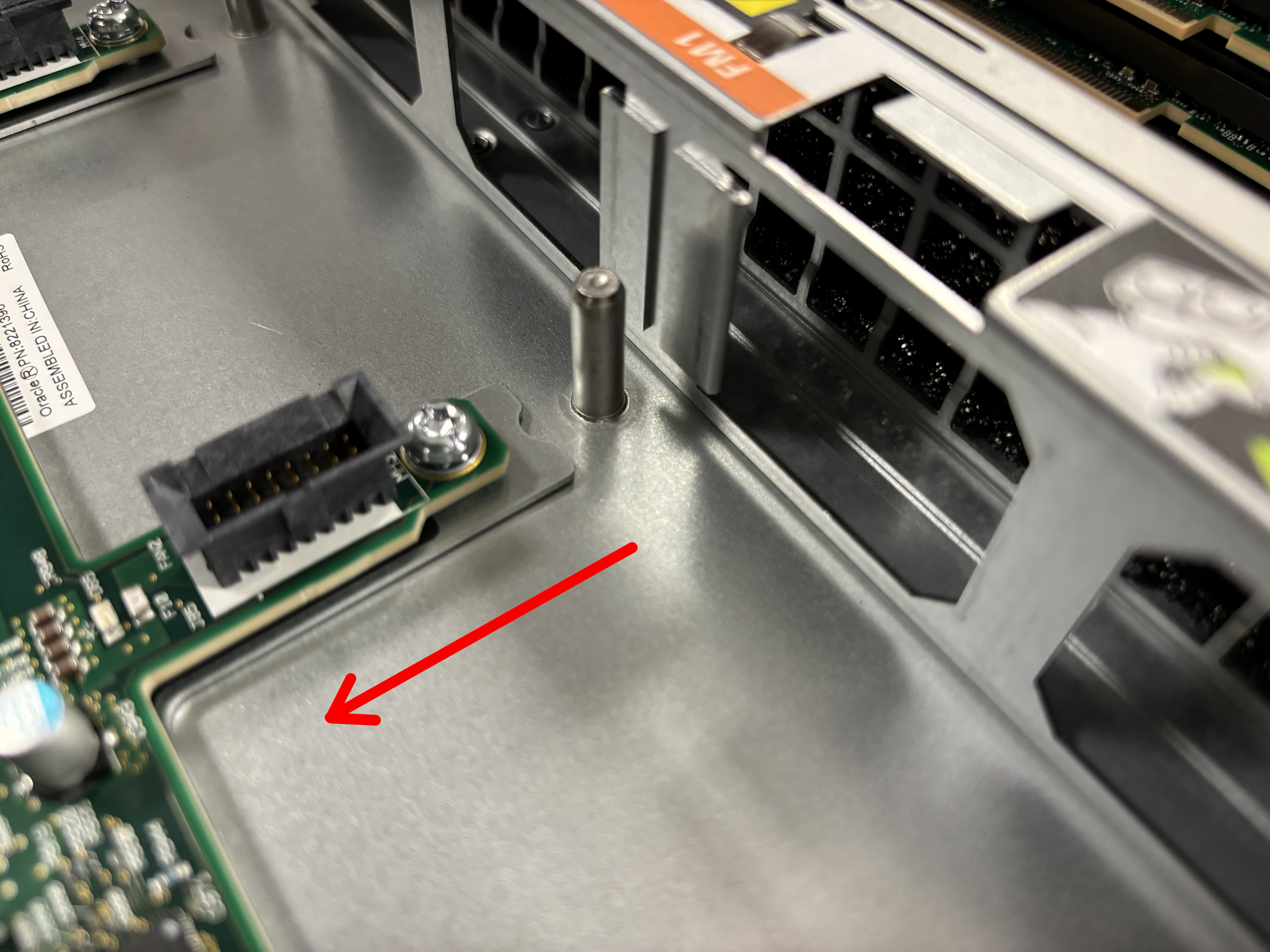
The IO connectors in the rear should penetrate their openings.
- Use a Torx T25 screwdriver to tighten the green captive screw near
the mainboard handle.

- Reconnect the FIM cable to the mainboard.
See Install the FIM.
- Reinstall the four fans.
See Install a Fan Module.
- Reinstall the two power supplies.
- Reinstall the top cover.
Use a T15 Torx tip screwdriver to lock the latch.
- Install the Acme Packet 6400 back into the rack.
- Reconnect the IO, power, and ground cables.