| Skip Navigation Links | |
| Exit Print View | |

|
Sun Blade X4-2B Service Manual |
Troubleshooting the Server Module
Servicing Server Module Components
Servicing a Storage Drive (CRU)
Identifying Storage Drive Indicators and Mechanical Components
Service Action Required Indicator
Lever and Lever Release Button
Storage Drive Failure and RAID
Remove Storage Drive Filler Panels
Insert Storage Drive Filler Panels
DIMM Fault Remind Circuit and ECC Errors
Fault Remind Button and Charge Status Indicator
Inconsistencies Between DIMM Fault LEDs and the BIOS Isolation of Faulty DIMMs
DIMM Population Rules and Guidelines
Detailed Memory Population Rules
Servicing USB Flash Sticks (CRU)
Servicing a Fabric Expansion Module (CRU)
Servicing a RAID Expansion Module (CRU)
Replace a REM Battery on the REM Card
Selecting the Correct Processor Removal/Replacement Tool
Processor Fault Remind Circuit
Fault Remind Button and Charge Status Indicator
Install a Processor Heat Sink (FRU)
Servicing the Motherboard Assembly (FRU)
Remove Motherboard Assembly Components (FRU)
Install Motherboard Assembly Components (FRU)
Servicing the System Battery (CRU)
Returning the Server Module to Operation
BIOS Power-On Self-Test (POST) Checkpoints
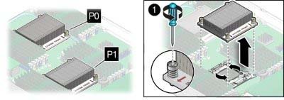
To replace a processor, you must first remove the processor heat sink. The heat sink sits on top of the processor and is secured to the motherboard by four screws. Once removed, retain the heat sink for reuse.
Caution - Component damage. Handle processor socket pins with extreme care. Processor and socket pins are very fragile. A light touch can bend the processor socket pins and damage the board beyond repair. |
Before You Begin
Required Tools A number 2 Phillips screwdriver is required for this procedure.
Turn each screw one and one half turns until they are fully disengaged.

A thin layer of thermal compound separates the heat sink and the processor. This compound also acts as an adhesive.
Next Steps