Component Designations
These sections show the designation and orientation of CRU and FRU components:
Fan Module Designations
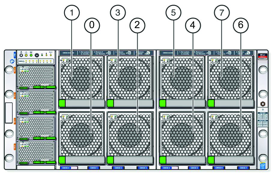
The eight fan modules (FMs) are directly accessible at the front of the server and are arranged in two stacked rows of four FMs.
-
Bottom row from left to right: FM 0, FM 2, FM 4, and FM 6.
-
Top row from left to right: FM 1, FM 3, FM 5, and FM 7.
|
The eight fan modules are installed in two fan frames The left frame contains FM 0, FM1, FM2, and FM 3. The right frame contains FM 4, FM 5, FM 6, and FM 7.
Each vertical pair of FMs provides cooling for the corresponding CPU modules (CMODs), which are located directly behind the FMs. For example, FMs 0 and 1 provide cooling for CMODs 0 and 1, and FMs 6 and 7 provide cooling for CMODs 6 and 7.
For CMOD designations, see CMOD Slot Designations.
Power Supply Slot Designations
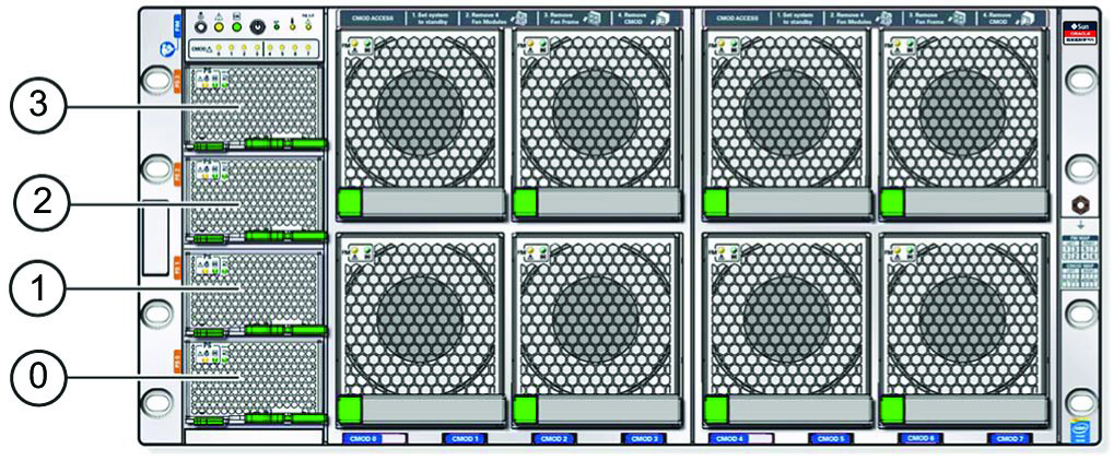
The four slots for the power supply units (PSUs) are directly accessible at the front of the server and are arranged in a single stacked row. They are designated from the bottom to the top as, PSU 0, PSU 1, PSU 2, and PSU 3. The following illustration shows the arrangement of the PSUs.
|
CMOD Slot Designations
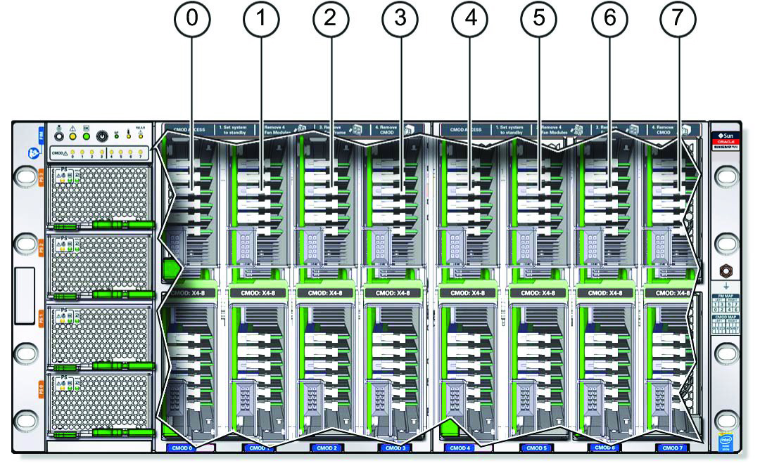
CPU module slots are arranged in a single row and are designated from left to right as, CMOD 0–CMOD 7. The CMOD slots are accessible from the front of the server by removing the FMs and frames.
The server is available with four CMODs or eight CMODs. Four-CMOD systems have CMODs in CMOD 0–CMOD 3, and filler panels in CMOD 4–CMOD 7.
For more information, see CPU Module (CMOD) Overview.
|
Memory Slot Designations
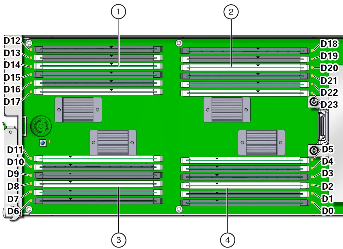
Each CMOD contains 24 DIMM slots arranged in four groups of six slots. The following illustration shows the groups and their slot designations.
|
See Also
Storage Drive Slot Designations
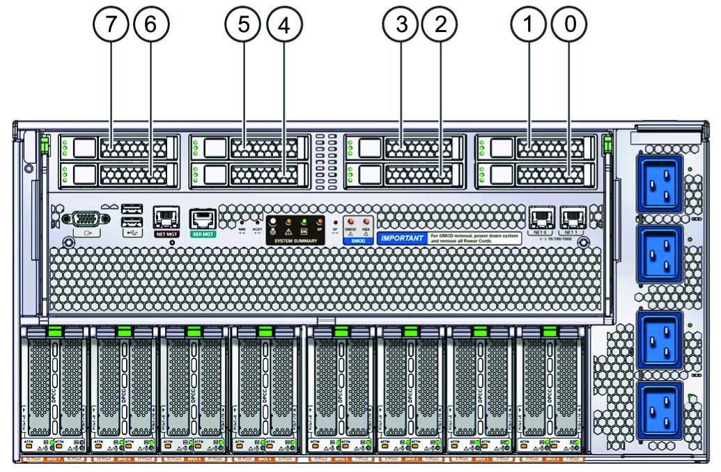
The eight storage drive slots are in the system module (SMOD) and directly accessible at the back of the server. Slots are arranged in two stacked rows of four slots and designated from right to left.
-
The top row contains slots 0, 2, 4, and 6.
-
The bottom row contains slots 1, 3, 5, and 7
|
DPCC and PCIe Card Slot Designations
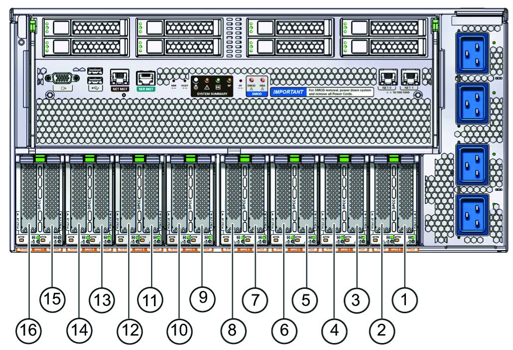
The eight dual PCIe card carrier (DPCC) slots are arranged in a single row at the back of the server. The slots are designated from right to left as, DPCC 0–DPCC 7.
Each DPCC supports two PCIe slots, for a total of 16. The PCIe slots are designated from right to left as PCIe 1–PCIe 16.
-
DPCC 0 contains PCIe slots 1 and 2
-
DPCC 1 contains PCIe slots 3 and 4
-
DPCC 2 contains PCIe slots 5 and 6
-
DPCC 3 contains PCIe slots 7 and 8
-
DPCC 4 contains PCIe slots 9 and 10
-
DPCC 5 contains PCIe slots 11 and 12
-
DPCC 6 contains PCIe slots 13 and 14
-
DPCC 7 contains PCIe slots 15 and 16
The following illustration shows the location and designations of the PCIe slots.
|
AC Input Power Block
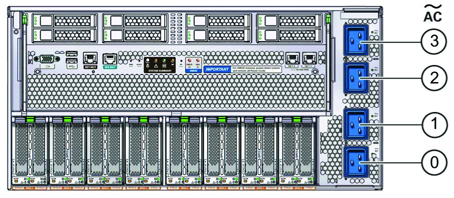
The four AC power inputs at the back of the server are arranged in a stack. Starting at the bottom, they are designated AC 0, AC 1, AC 2, and AC 3. The designations match the corresponding PSUs.
The AC power block is not a removable component.
The following illustration shows the location and designation of the inlets on the AC power block.
|