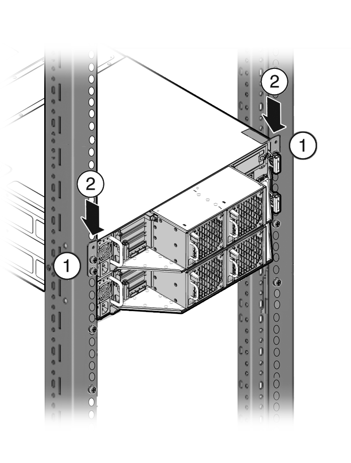
4 Installing the System Into a Rack
This chapter includes the following sections:
Task Overview
Follow the appropriate procedures to rack mount your system.
Note:
These procedures describe how to insert the system into a rack. For cabling instructions, refer to the appropriate Deployment and User's Guide for the Oracle Database Appliance X6 series or the Getting Started Guide for the Oracle Database Appliance X3-2/X4-2/X5-2 or Version 1.| Oracle Database Appliance Version 1 | Oracle Database Appliance X3-2/X4-2 | Oracle Database Appliance X5-2 and X6-2-HA | Oracle Database Appliance X6-2S/X6-2M/X6-2L |
|---|---|---|---|
|
|
|
Optional Component Installation
Standard system components are installed at the factory. Optional components that you purchased independent of the standard configuration are shipped separately, and in most cases should be installed before you install the server in a rack.
The following optional components can be ordered separately:
-
DIMM memory kits:
-
For Oracle Database Appliance X6-2S, you have the option of ordering memory expansion to 384 GB. Memory kits come in sets of 8 x 32 GB DIMMs.
-
For Oracle Database Appliance X6-2M/X6-2L, you have the option of ordering memory expansion to 512 GB or 768 GB. Memory kits come in sets of 8 x 32 GB DIMMs.
-
For Oracle Database Appliance X5-2 and Oracle Database Appliance X6-2-HA, you have the option of ordering memory expansion to 512 GB or 768 GB. Memory kits come in sets of 8 x 32 GB DIMMs, which means you need two kits (one for each server node) for 512 GB, and four kits (two for each server node) for 768 GB. Both server nodes must have the same amount of memory.
Refer to the Service Manual for instructions on installing memory.
-
-
Storage drives:
-
For Oracle Database Appliance X6-2S/X6-2M with the default configuration of two NVMe drives, you have the option of ordering two additional 2.5-inch 3.2 TB NVMe SSDs for slots NVMe 2-3. Drives must be installed in pairs.
-
For Oracle Database Appliance X6-2L with the default configuration of six NVMe drives, you have the option of ordering three additional 2.5-inch 3.2 TB NVMe SSDs for slots NVMe2, NVMe5 and NVMe8. Drives must be installed as a set of three. Drive slots NVMe9, NVMe10 and NVMe11 are not supported for use with this product.
-
For Oracle Database Appliance X6-2-HA with a fully populated storage shelf, you can add an optional storage expansion shelf.
Note:
You cannot add a storage expansion shelf to an appliance with a base storage shelf configuration that is half populated (filler panels in slots 10-19).
Refer to the Service Manual for instructions on installing storage drives.
-
-
Other optional configurations:
For Oracle Database Appliance X5-2, you have the option of ordering two Sun Dual 10GbE SFP+ PCIe 2.0 Low Profile Adapters to replace the two standard InfiniBand adapters (one in each server node) to support an Ethernet fiber connection to the data center or public network (it cannot be used for the appliance private node-to-node connection).
To replace the standard InfiniBand adapter, refer to the Service Manual for instructions on replacing a PCIe card in Slot 1. After the card is replaced, refer to the Getting Started Guide for instructions on cabling and software configuration.
Safety Precautions When Rackmounting
This section describes safety precautions you must follow when installing the server into a rack.
Caution:
Personal injury or equipment damage. Prevent the rack from tipping over. 1) Deploy the anti-tilt bar or legs on the equipment rack before beginning an installation. 2) Always load equipment into a rack from the bottom up so that the rack will not become top-heavy and tip over. 3) Mount equipment in the rack such that it does not create uneven or dangerous mechanical loading. 4) Do not use slide-rail mounted equipment as a shelf or workspace.Caution:
Equipment damage caused by elevated temperature. 1) If you install the equipment in a closed or multi-unit rack assembly, ensure that the operating ambient temperature inside the rack does not exceed the maximum ambient temperature specified for the server. For server environmental requirements, see Environmental Specifications. 2) Install the equipment in the rack such that airflow is not restricted or impeded.Caution:
Supply circuit damage and data loss. The AC circuits used to supply power to the system must be rated for the maximum amount of power that the system requires. See Electrical Specifications for input power requirements.Caution:
Equipment damage. Maintain reliable earthing. Pay particular attention to supply connections other than direct connections to the branch circuit (for example, use of power strips).ESD Precautions
Caution:
Equipment damage. To prevent damage from electrostatic discharge, use the following precautions when installing or servicing components.-
Place components on an antistatic surface, such as an antistatic discharge mat, an antistatic bag, or a disposable antistatic mat.
-
Wear an antistatic grounding strap connected to a metal surface on the chassis when you work on system components.
Rack Compatibility Requirements
The rack-mounting hardware can be used only in specialized racks that meet the requirements in the following tables.
For Oracle Database Appliance X6-2 series:
| Feature | Oracle Database Appliance X6-2S/X6-2M | Oracle Database Appliance X6-2L | Oracle Database Appliance X6-2-HA |
|---|---|---|---|
|
Rack structure |
Four-post rack (mounting at both front and rear). Two-post racks are not compatible. |
Four-post rack (mounting at both front and rear). Two-post racks are not compatible. |
Four-post rack (mounting at both front and rear). Two-post racks are not compatible. |
|
Space available |
Must have 1RU (rack units) of space available. |
Must have 2RU of space available. |
6RU without optional storage expansion shelf. 10RU with optional storage expansion shelf. |
|
Rack horizontal opening and unit vertical pitch |
Conforms to ANSI/EIA 310-D-1992 or IEC 60927 standards. |
Conforms to ANSI/EIA 310-D-1992 or IEC 60927 standards. |
Conforms to ANSI/EIA 310-D-1992 or IEC 60927 standards. |
|
Distance between front and rear mounting planes |
Minimum 610 mm and maximum 915 mm (24 in to 36 in). |
Minimum 610 mm and maximum 915 mm (24 in to 36 in). |
Minimum 610 mm and maximum 915 mm (24 in to 36 in). |
|
Clearance depth in front of front mounting plane |
Distance to front cabinet door is at least 25.4 mm (1 in). |
Distance to front cabinet door is at least 25.4 mm (1 in). |
Distance to front cabinet door is at least 25.4 mm (1 in). |
|
Clearance depth behind front mounting plane |
Distance to rear cabinet door is at least 900 mm (35.43 in) with the cable management arm, or 800 mm (31.5 in) without the cable management arm. |
Distance to rear cabinet door is at least 900 mm (35.43 in) with the cable management arm, or 800 mm (31.5 in) without the cable management arm. |
Distance to rear cabinet door is at least 900 mm (35.43 in) with the cable management arm, or 800 mm (31.5 in) without the cable management arm. |
|
Clearance width between front and rear mounting planes |
Distance between structural supports and cable troughs is at least 456 mm (18 in). |
Distance between structural supports and cable troughs is at least 456 mm (18 in). |
Distance between structural supports and cable troughs is at least 456 mm (18 in). |
|
Minimum clearance for service access |
Front clearance: 123.2 cm (48.5 in) Rear clearance: 91 cm (36 in) |
Front clearance: 123.2 cm (48.5 in) Rear clearance: 91 cm (36 in) |
Front clearance: 123.2 cm (48.5 in) Rear clearance: 91 cm (36 in) |
|
Server node dimensions |
Height: 42.6 mm (1.7 in) Width: 436.5 mm (17.2 in) Depth: 737 mm (29 in) |
Height: 87.6 mm (3.45 in) Width: 436.5 mm (17.2 in) Depth: 737 mm (29 in) |
Height: 42.6 mm (1.7 in) Width: 436.5 mm (17.2 in) Depth: 737 mm (29 in) |
|
Storage shelf dimensions |
N/A |
N/A |
Height: 175 mm (6.9 in) Width: 483 mm (19 in) Depth: 630 mm (24.8 in) |
For Oracle Database Appliance Version 1 and Oracle Database Appliance X3-2/X4-2/X5-2:
| Feature | Oracle Database Appliance Version 1 | Oracle Database Appliance X3-2/X4-2 | Oracle Database Appliance X5-2 |
|---|---|---|---|
|
Rack structure |
Four-post rack (mounting at both front and rear). Two-post racks are not compatible. |
Four-post rack (mounting at both front and rear). Two-post racks are not compatible. |
Four-post rack (mounting at both front and rear). Two-post racks are not compatible. |
|
Space available |
Must have 4RU (rack units) of space available. |
4RU without optional storage expansion shelf. 6RU with optional storage expansion shelf. |
6RU without optional storage expansion shelf. 10RU with optional storage expansion shelf. |
|
Rack horizontal opening and unit vertical pitch |
Conforms to ANSI/EIA 310-D-1992 or IEC 60927 standards. |
Conforms to ANSI/EIA 310-D-1992 or IEC 60927 standards. |
Conforms to ANSI/EIA 310-D-1992 or IEC 60927 standards. |
|
Distance between front and rear mounting planes |
Minimum 660.4 mm and maximum 876.3 mm (26 in to 34.5 in). |
Minimum 610 mm and maximum 915 mm (24 in to 36 in). |
Minimum 610 mm and maximum 915 mm (24 in to 36 in). |
|
Clearance depth in front of front mounting plane |
Distance to front cabinet door is at least 25.4 mm (1 in). |
Distance to front cabinet door is at least 25.4 mm (1 in). |
Distance to front cabinet door is at least 25.4 mm (1 in). |
|
Clearance depth behind front mounting plane |
Distance to rear cabinet door is at least 700 mm (27.5 in). |
Distance to rear cabinet door is at least 900 mm (35.43 in) with the cable management arm, or 800 mm (31.5 in) without the cable management arm. |
Distance to rear cabinet door is at least 900 mm (35.43 in) with the cable management arm, or 800 mm (31.5 in) without the cable management arm. |
|
Clearance width between front and rear mounting planes |
Distance between structural supports and cable troughs is at least 456 mm (18 in). |
Distance between structural supports and cable troughs is at least 456 mm (18 in). |
Distance between structural supports and cable troughs is at least 456 mm (18 in). |
|
Minimum clearance for service access |
Front clearance: 123.2 cm (48.5 in) Rear clearance: 91 cm (36 in) |
Front clearance: 123.2 cm (48.5 in) Rear clearance: 91 cm (36 in) |
Front clearance: 123.2 cm (48.5 in) Rear clearance: 91 cm (36 in) |
|
Server node dimensions |
Height: 175.1 mm (6.9 in) Width (without mounting ears): 437 mm (17.2 in) Width (with mounting ears): 482.6 mm (19 in) Depth: 762 mm (30 in) |
Height: 42.6 mm (1.7 in) Width: 436.5 mm (17.2 in) Depth: 737 mm (29 in) |
Height: 42.6 mm (1.7 in) Width: 436.5 mm (17.2 in) Depth: 737 mm (29 in) |
|
Storage shelf dimensions |
N/A |
Height: 87.9 mm (3.5 in) Width: 483 mm (19 in) Depth: 630 mm (24.8 in) |
Height: 175 mm (6.9 in) Width: 483 mm (19 in) Depth: 630 mm (24.8 in) |
Caution:
Personal injury or equipment damage. Always load equipment into a rack from the bottom up so that it will not become top-heavy and tip over. Deploy your rack’s anti-tilt bar to prevent the rack from tilting during equipment installation. This caution is not applicable if an earthquake kit has been installed on the rack and it is bolted to the floor.Inserting Oracle Database Appliance Into a Rack
This section describes how to install an Oracle Database Appliance into a rack as follows:
-
Inserting Oracle Database Appliance X6-2S/X6-2M/X6-2L Into a Rack
-
Inserting Oracle Database Appliance X3-2/X4-2/X5-2 and X6-2-HA Into a Rack
Inserting Oracle Database Appliance X6-2S/X6-2M/X6-2L Into a Rack
This section describes how to install Oracle Database Appliance X6-2S/X6-2M/X6-2L server into a rack. If you are installing an Oracle Database Appliance X3-2, Oracle Database Appliance X4-2, or Oracle Database Appliance X5-2, see Inserting Oracle Database Appliance X3-2/X4-2/X5-2 and X6-2-HA Into a Rack. If you are installing Oracle Database Appliance Version 1, see Inserting Oracle Database Appliance Version 1 Into a Rack.
This section includes the following subsections:
Caution:
Personal injury or equipment damage. Always install equipment in a rack from the bottom up.Caution:
System Failure. Oracle Database Appliance is shipped with matched sets of components that must be installed together. Mixing components from different systems might cause the system to fail.Contents of the Shipping Container
Inspect the shipping cartons of your Oracle Database Appliance X6-2S/X6-2M/X6-2L system for evidence of physical damage. If a shipping carton appears damaged, request that the carrier's agent be present when the carton is opened. Keep all contents and packing material for the agent's inspection.
The ship kit for the server includes the following items:
-
Power cords, packaged separately with country kit
-
Rail kit containing rack rails, hardware, template and installation instructions
-
Miscellaneous hardware, cables, and connectors
-
Setup booklet
-
Legal and safety documents
Tools and Equipment Needed
Obtain the following tools and equipment before beginning the installation of Oracle Database Appliance X6-2S/X6-2M/X6-2L.
-
Phillips head No. 2 screwdriver that is a minimum of 4 inches long
-
T20 Torx driver if using a threaded rack
-
A mechanical lift is highly recommended
Stabilize the Rack for Installation
Caution:
Personal injury or equipment damage. To reduce the risk of personal injury, stabilize the rack cabinet, and extend all anti-tilt devices before installing the server.See your rack documentation for detailed instructions for the following steps.
- Open and remove the front and rear doors from the rack cabinet.
Note:
The front and rear doors need to be removed only if they interfere with the installation. - To prevent the rack cabinet from tipping during the installation, fully extend the rack cabinet's anti-tilt legs or anti-tilt bar, which are located at the bottom front of the rack cabinet.
- If there are leveling feet beneath the rack cabinet to prevent it from rolling, extend these leveling feet fully downward to the floor.
Installing the Server Node Into a Rack
Use the instructions in this section to install Oracle Database Appliance X6-2 series server node in the rack.
Note:
The links in the following table take you to instructions outside of the Oracle Database Appliance library to the Oracle Server X6-2 or Oracle Server X6-2L documentation libraries. Use your browser's Back button to return to the Oracle Database Appliance library.| Oracle Database Appliance X6-2S/X6-2M | Oracle Database Appliance X6-2L |
|---|---|
Inserting Oracle Database Appliance X3-2/X4-2/X5-2 and X6-2-HA Into a Rack
This section describes how to install the server nodes and storage shelves of Oracle Database Appliance X3-2, Oracle Database Appliance X4-2, Oracle Database Appliance X5-2 or Oracle Database Appliance X6-2-HA into a rack. If you are installing an Oracle Database Appliance X6-2S/X6-2M/X6-2L, see Inserting Oracle Database Appliance X6-2S/X6-2M/X6-2L Into a Rack. If you are installing Oracle Database Appliance Version 1, see Inserting Oracle Database Appliance Version 1 Into a Rack.
This section includes the following subsections:
Caution:
Personal injury or equipment damage. Always install equipment in a rack from the bottom up. See Installation Sequence.Caution:
System Failure. Oracle Database Appliance is shipped with matched sets of components that must be installed together. Mixing components from different systems might cause the system to fail.Contents of the Shipping Pallet
Oracle Database Appliance X3-2, Oracle Database Appliance X4-2, Oracle Database Appliance X5-2 and Oracle Database Appliance X6-2-HA are shipped with the entire system on a single pallet. It includes all server nodes, storage shelves, mounting hardware, cables, and labels.
Caution:
System failure. All items in a shipment are designed to be used together as a single system. Do not mix components from different shipments; this could cause the system to fail. For details, see Verify Component Compatibility.The items in this shipment include:
-
Server node 0 and server node 1
-
Rackmounting hardware, cables, and labels for server nodes 0 and 1
-
One storage shelf
-
Rackmounting hardware for the storage shelf
If you ordered a storage expansion shelf, it is shipped separately.
Installation Sequence
Always install equipment in a rack starting at the bottom and working upwards. For Oracle Database Appliance X3-2, Oracle Database Appliance X4-2, Oracle Database Appliance X5-2 and Oracle Database Appliance X6-2-HA, install the equipment in the following order:
-
Storage expansion shelf, if equipped.
-
Storage shelf.
-
Server node 0.
-
Server node 1.
Verify Component Compatibility
For Oracle Database Appliance X3-2, Oracle Database Appliance X4-2, Oracle Database Appliance X5-2 and Oracle Database Appliance X6-2-HA, all appliance components that are bundled at the factory have a Top Level Identifier (TLI) number that is matched for the system. Both server nodes, the storage shelf, and the (optional) storage expansion shelf (if included in the initial appliance configuration from the factory), must have the same TLI.
Note:
If you add a storage expansion shelf to the system after the initial installation (that is, the storage expansion shelf was not part of the initial configuration order for the appliance), its TLI will be different from the rest of the system. In this scenario, an add-on component having a different TLI from the main appliance TLI is appropriate.- Locate the TLI for both server nodes, the storage shelf, and (if present) the storage expansion shelf.
The TLI label is on top of the component, on the left-hand side, near the front.

- Check to ensure that all components have the same TLI numbers (a TLI part number and TLI serial number).
Tools and Equipment Needed
Obtain the following tools and equipment before beginning the installation of Oracle Database Appliance X3-2, Oracle Database Appliance X4-2, Oracle Database Appliance X5-2, or Oracle Database Appliance X6-2-HA.
-
Phillips head No. 2 screwdriver that is a minimum of 4 inches long
-
T20 Torx driver if using a threaded rack
-
A mechanical lift is highly recommended
Caution:
Personal injury or equipment damage. The storage shelf weighs approximately 51 lbs (23 kg). If no mechanical lift is available, use three people to place it in the rack.
Stabilize the Rack for Installation
Caution:
Personal injury or equipment damage. To reduce the risk of personal injury, stabilize the rack cabinet, and extend all anti-tilt devices before installing the server.See your rack documentation for detailed instructions for the following steps.
- Open and remove the front and rear doors from the rack cabinet.
Note:
The front and rear doors need to be removed only if they interfere with the installation. - To prevent the rack cabinet from tipping during the installation, fully extend the rack cabinet's anti-tilt legs or anti-tilt bar, which are located at the bottom front of the rack cabinet.
- If there are leveling feet beneath the rack cabinet to prevent it from rolling, extend these leveling feet fully downward to the floor.
Applying Labels
Oracle Database Appliance X3-2, Oracle Database Appliance X4-2, Oracle Database Appliance X5-2 and Oracle Database Appliance X6-2-HA are shipped with a label kit that provides four labels, to be applied to the front of each server node and storage shelf.
To Apply Labels to Server Nodes and Storage Shelves
- Find the labels.
Depending on your model, the shipping kit might include server node labels and a sheet with storage shelve labels.
-
Oracle Database Appliance X5-2 and Oracle Database Appliance X6-2-HA systems only include server node labels to attach. The storage shelf labels are attached at the factory.
-
Oracle Database Appliance X3-2 and Oracle Database Appliance X4-2 systems include both server node and storage shelf labels that you need to attach.
-
- Verify that the locations where the labels need to go are clean, and free of grease and dirt.
- Apply the labels where needed:
For labels that you attach, peel off the backing sheet and apply the label to the corresponding spot on the right-hand side of the appliance front panel.
-
Server Node 1: Apply this label to the top server node [1].
-
Server Node 0: Apply this label to the lower server node [2].
-
Storage shelf: Apply this label to the storage shelf directly beneath server node 0 [3].
-
Storage expansion shelf (optional): Apply this label to the bottom storage shelf, if one is present [4].
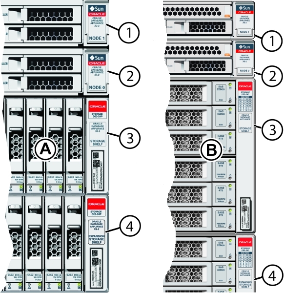
Callout Description A
Oracle Database Appliance X3-2 and Oracle Database Appliance X4-2
B
Oracle Database Appliance X5-2 and Oracle Database Appliance X6-2-HA
1
Server node 1
2
Server node 0
3
Storage shelf
4
Optional storage expansion shelf
-
Installing the Storage Shelves Into a Rack
This section includes instructions for installing the storage shelf into a rack.
Oracle Database Appliance X3-2, Oracle Database Appliance X4-2, Oracle Database Appliance X5-2 and Oracle Database Appliance X6-2-HA require one storage shelf and might include a second storage shelf, called the storage expansion shelf. Both are installed in the same way, with the following caveats:
-
If you have a storage expansion shelf, install it first. Follow the procedure for your system:
-
If you are adding a storage expansion shelf to an existing system, see Add a Storage Expansion Shelf Into an Existing System for additional details.
Install the Oracle Database Appliance X6-2-HA DE3-24C Storage Shelf Into a Rack
The Oracle Storage Drive Enclosure DE3-24C requires four standard mounting units (4RU) of vertical space in the cabinet.
Before You Begin
-
Ensure that your site meets the requirements in Oracle Database Appliance Specifications
-
Ensure that the rack meets the requirements in Rack Compatibility Requirements
Note:
The rail kit included with the shelf can only be used with EIA compliant 9.5 mm square hole racks or 7.0 mm diameter round hole racks. -
Observe all precautions in Safety Precautions When Rackmounting
- Starting at the bottom of the cabinet, locate the appropriate rack unit (RU) height.
Storage shelves must be installed below the server nodes to prevent the rack from tipping.
- Open the storage shelf rail kit box and find the cage nut packets included with the kit, and confirm if your rack uses square or round holes.
The cage nut packets include a special template for either round or square hole racks for positioning the cage nuts.
Note:
The following steps show rail kit installation with a square hole rack. The same steps would apply for a round hole rack.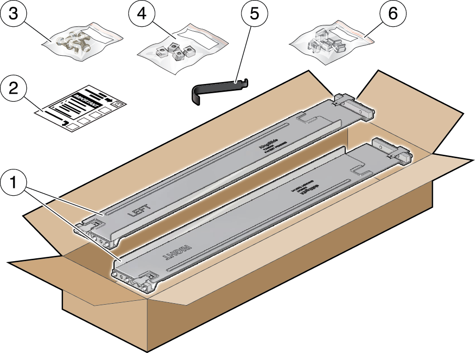
No. Description 1
Two adjustable storage shelf rails
2
Cage nut installation template
3
Six rear 10-32 7mm shipping screws (2 are spares)
4
Four round 7mm 10-32 cage nuts per set (2 are spares). Only one set is required, either square or round.
5
Cage nut tool
6
Four square 9.5mm 10-32 cage nuts per set (2 are spares). Only one set is required, either square or round.
- Attach the storage shelf rails to the rack, as follows:
- Orient the rail so that the stamped label (LEFT or RIGHT) is facing the inside of the rack.
- Adjust the rail length to fit the front and rear of the rack.
Note:
Mark which rack rail holes you will be using to ensure the storage shelf rails are installed evenly and correctly the first time. - Hold open the rail clamp at each end of the rail by pressing the clamp lever [1] and insert both ends of the rail into the appropriate rack holes [2].
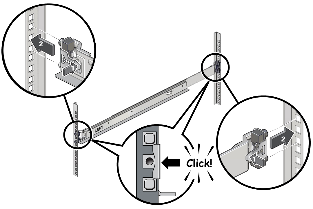
- Close the rail clamps over the rails by releasing the clamp lever.
You will hear an audible click as the clamps lock in place over the rack rails.
- Repeat steps 3a through 3d for the second rail.
- Install one screw through the rack and into the rear of each rail.
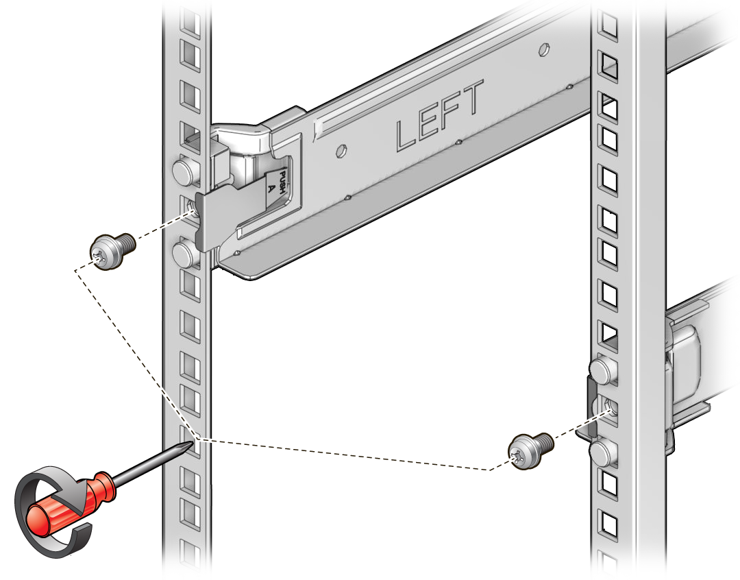
- Install the front cage nuts.
Caution:
Installing the storage shelf without the front cage nuts will cause the storage shelf to be unstable. You would then need to remove the storage shelf from the rack to install the cage nuts.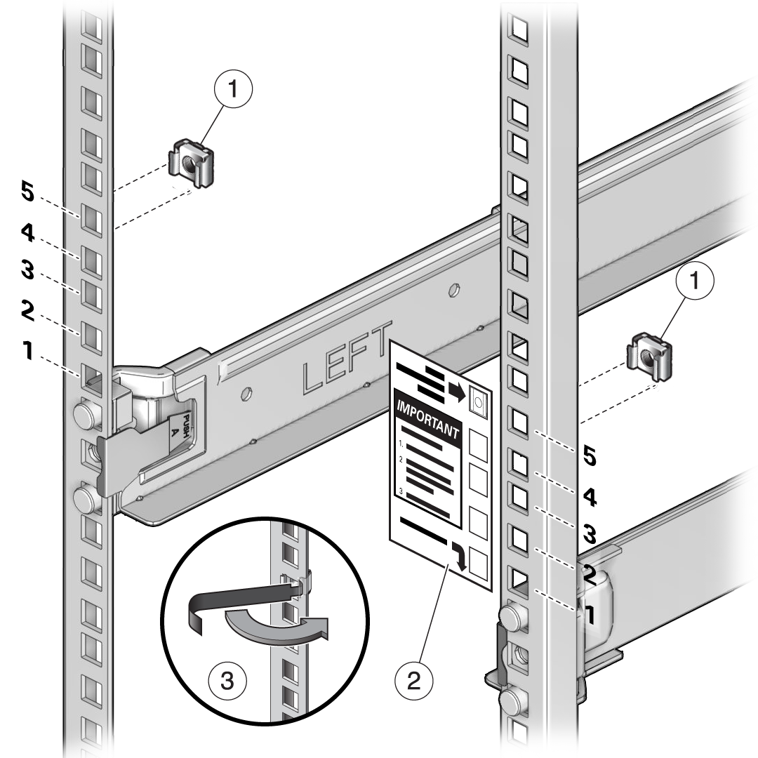
No. Description 1
Cage nuts
2
Cage nut installation template
3
Cage nut tool
- Use the template [2] to determine cage nut placement.
- Retrieve a cage nut and hook one lip of the nut into the appropriate rail hole [1].
- Insert the tip of the cage nut insertion tool through the rail hole [3] and hook the other lip of the cage nut. Pull the cage nut through the hole until the lip snaps into place.
- Repeat through steps 5a through 5c for the second cage nut.
- Using a mechanical lift or three people, one at each side of the storage shelf and one in front, carefully lift and rest the shelf on the bottom ledge of the left and right rails. Do not lift using the power supply handles.
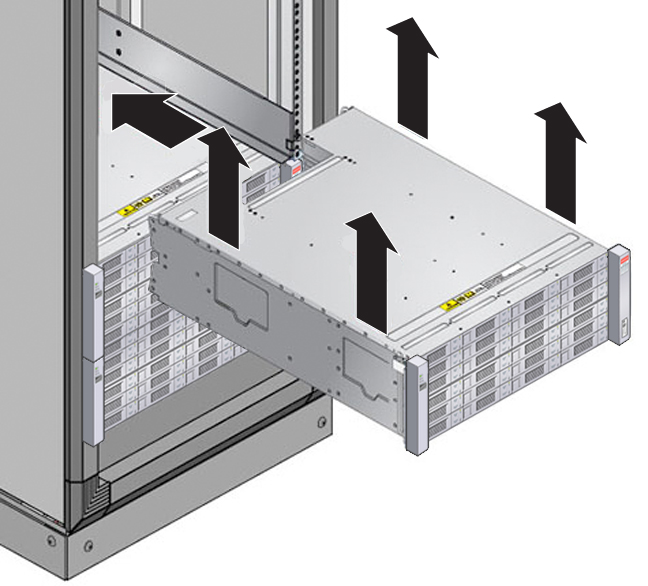
- Carefully slide the shelf into the cabinet. Ensure that the shelf is fully seated within the rails. If removing the shelf to reseat it, support it at all times.
- Secure the front of the shelf using the four captive securing screws [1 - 4].
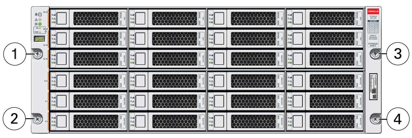
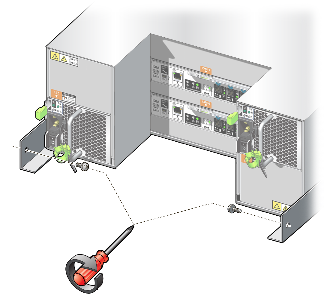
- To secure the storage shelf in the rack for shipping, install a screw in each rear storage shelf chassis ear.
- Repeat these steps if you have an additional storage shelf to install.
Install the Oracle Database Appliance X5-2 DE2-24C Storage Shelf Into a Rack
The Oracle Storage Drive Enclosure DE2-24C requires four standard mounting units (4RU) of vertical space in the cabinet. Starting at the bottom of the cabinet, locate the appropriate rack unit (RU) height. Install storage shelves below controllers to prevent the rack from tipping.
Before You Begin
This task provides instructions for both threaded and unthreaded racks.
-
Ensure that your site meets the requirements in Oracle Database Appliance Specifications
-
Ensure that the rack meets the requirements in Rack Compatibility Requirements
-
Observe all precautions in Safety Precautions When Rackmounting
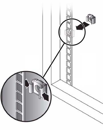
- If using an unthreaded universal 19-inch or Sun Rack II cabinet, snap one supplied cage nut into the 8th rack hole, counting upward, in each front rail of the 4RU space.
- Prepare the screws in each rail end:
-
Square-hole unthreaded cabinet: No preparation.
-
Round-hole unthreaded cabinet: Remove the screws from each rail end and discard. Locate the screws for round-hole cabinets and place aside.
-
Threaded cabinet: Remove screws and replace them in the opposite direction (from the inside of the rail flange) so they act as location pins. Also remove the clip nut from each front rail end and discard.
-
- Position the front of the rails inside the cabinet, with the rail flange inside of the cabinet flange, and the rail label facing the inside of the cabinet.
-
Square-hole unthreaded cabinet: The screw heads fit inside the rack holes.
-
Round-hole unthreaded cabinet: Install two screws through the rack and into the front of each rail. Do not install into the cage nut in the rack, or the clip nut on the rail.
-
Threaded cabinet: The location pins fit inside the rack holes.
-
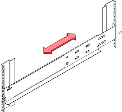
- Adjust the rail lengths to fit.
- Install one screw through the rack and into the rear of each rail.
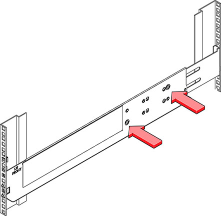
- Tighten the two locking screws in the rails.
- Using a mechanical lift or three people, one at each side of the storage shelf and one in front, carefully lift and rest the shelf on the bottom ledge of the left and right rails. Do not lift using the power supply handles.
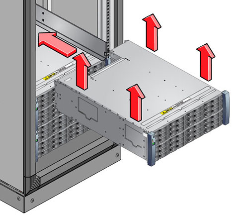
- Carefully slide the shelf into the cabinet. Ensure that the shelf is fully seated within the rails. If removing the shelf to reseat it, support it at all times.
- Remove the front side caps, install two screws into each front side, and replace the caps.
- Install one long patchlock screw per rail to secure the rear of the shelf to the rear of the rack.
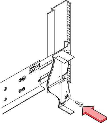
- Repeat these steps if you have an additional storage shelf to install.
Install the Oracle Database Appliance X3-2/X4-2 DE2-24P Storage Shelf Into a Rack
The Oracle Storage Drive Enclosure DE2-24P requires two standard mounting units (2RU) of vertical space in the cabinet. The storage shelf rack-mount kit contains two rack rails, long and short M6 screws, and a 10mm wrench.
Before You Begin
This task provides instructions for both threaded and unthreaded racks.
-
Ensure that your site meets the requirements in Oracle Database Appliance Specifications
-
Ensure that the rack meets the requirements in Rack Compatibility Requirements
-
Observe all precautions in Safety Precautions When Rackmounting
- Install the rails in the rack.
- If you have an unthreaded rack:
- Position the front rail location pegs [1] fully inside the appropriate holes in the front of the rack.
The rail flange [2] must be inside of the cabinet flange, and the rail label facing the inside of the cabinet.
- Insert and loosely tighten one screw through the front of the rack and into the top hole in the rails [3].
- Insert and loosely tighten one screw through the back of the rack and into the back of the rails [4].
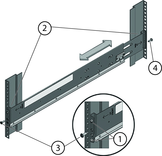
Callout Description 1
Location pegs
2
Rail flange and label
3
Front mounting screw
4
Rear mounting screw
- Position the front rail location pegs [1] fully inside the appropriate holes in the front of the rack.
- If you have a threaded rack:
- Use the T20 Torx driver to remove the rail location pegs from the front and rear of the rails [1].
- Use a 10mm wrench (supplied) to insert the pins into the ends of the rails where you removed the location pegs [1].
- Position the front of the rails inside the cabinet, with the rail flange inside of the cabinet flange, and the rail label facing the inside of the cabinet [2].
The pins should be fully located within the rack holes.
- Insert and loosely tighten one screw through the front of the rack and into the top hole in the rails [3].
The screws for threaded racks have an unthreaded area near the top of the shaft. Before threading these screws into the rails, thread them through the rack until the threads clear the rack and the screws turn freely.
Caution:
Mechanical failure. When installing a storage shelf in a threaded rack, be sure to use the screws with the partially unthreaded shaft. Before threading them into the rails, be sure to thread them through the rack until the threads clear the rack and the screws turn freely.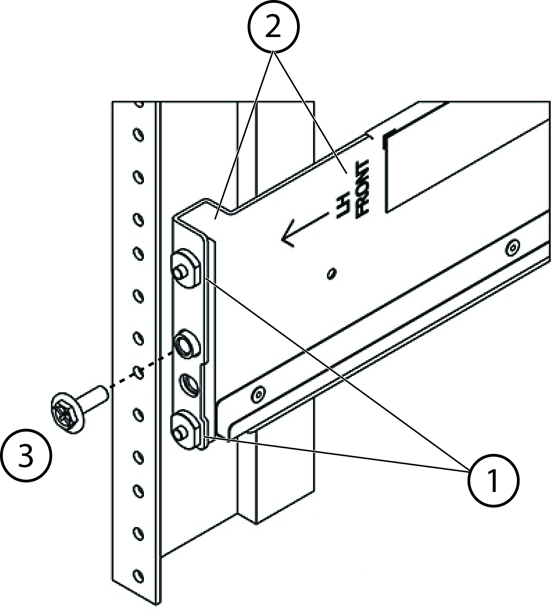
Callout Description 1
Pins (these replaced the location pegs)
2
Rail flange and label
3
Front mounting screw
- Adjust the rail lengths to fit, and locate the rear pins inside the corresponding rear rack holes [1].
- Insert and loosely tighten one screw through the back of the rack and into the back of the rails [2].
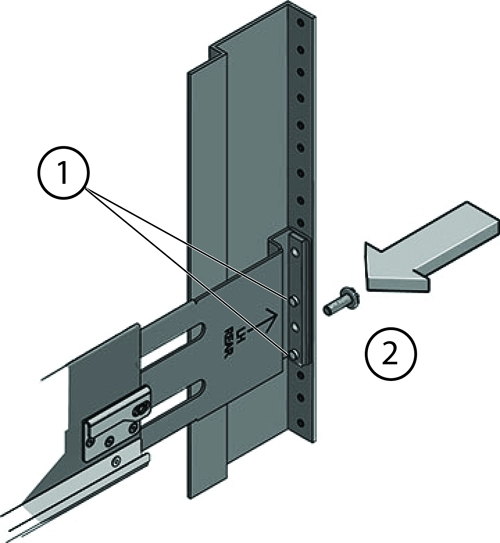
Number Description 1
Pins (replace location pegs)
2
Rear mounting screw
- If you have an unthreaded rack:
- Carefully slide the storage shelf onto the shelf rails until it is fully seated in the rack.
Caution:
Equipment damage. Do not lift the storage shelf using the handles on the power supply/fan module.Caution:
Personal injury or equipment damage. Use a mechanical lift, or three persons. If you are using three persons, use two to lift the storage shelf into place, and a third to check that it is resting securely on the rails before releasing it. - Pull the storage shelf partway out of the rack until it is approximately 7.8 inches (200 mm) out of the rack.
- Tighten the four screws that fasten the rails to the rack (two in front, two in back).
- Slide the storage shelf back into the rack and check to ensure that it is resting securely on the rails.
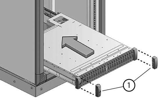
- Remove the front end caps that cover the ears on the front of the storage shelf [1]. They snap off.
- Use one short screw on each side to fasten the front of the storage shelf to the rack.
- Snap the end caps back onto the storage shelf.
- Use one short screw per rail to secure the rear of the storage shelf to threaded hole on the rail.
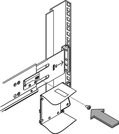
- Repeat these steps if you have an additional storage shelf to install.
Add a Storage Expansion Shelf Into an Existing System
Before You Begin
This task assumes that you are adding a storage expansion shelf to an already running Oracle Database Appliance X3-2, Oracle Database Appliance X4-2, Oracle Database Appliance X5-2, or Oracle Database Appliance X6-2-HA (must already have a fully populated storage shelf).
It is not necessary to shut down your system to complete this task.
Please note the following exceptional conditions:
-
The storage expansion shelf normally sits at the bottom of Oracle Database Appliance, beneath the storage shelf. However, since racks should always be provisioned from the bottom up, that space might be unavailable. In these cases, to avoid re-rackmounting the entire system, it can be placed above the server nodes, or even in a different rack.
-
The Top Level Identifier (TLI) on the storage expansion shelf will not match the rest of the system as described in Verify Component Compatibility. However, adding a storage expansion shelf after your initial purchase and setup of the appliance is a supported configuration.
- Apply the label, if needed.
The expansion storage shelf shipment includes a label that says "EXPANSION STORAGE SHELF". If the label is not already applied to the front of the shelf, apply it now as described in Applying Labels.
- Install the expansion storage shelf as described in Installing the Storage Shelves Into a Rack.
- Cable, power-on, and verify that the new storage is added.
Refer to the appropriate Getting Started Guide or Deployment and User's Guide for additional information.
Installing the Server Nodes Into a Rack
Use the instructions in this section to install server nodes in the rack.
Note:
The links in the following table take you to instructions outside of the Oracle Database Appliance library to the Sun Server X3-2, Sun Server X4-2, Oracle Server X5-2 and Oracle Server X6-2 documentation libraries. Use your browser's Back button to return to the Oracle Database Appliance library.| Oracle Database Appliance X3-2 | Oracle Database Appliance X4-2 | Oracle Database Appliance X5-2 | Oracle Database Appliance X6-2-HA |
|---|---|---|---|
|
|
|||
|
|
|
Inserting Oracle Database Appliance Version 1 Into a Rack
This section describes inserting Oracle Database Appliance Version 1 into a rack. If you are installing an Oracle Database Appliance X6-2S/X6-2M/X6-2L, see Inserting Oracle Database Appliance X6-2S/X6-2M/X6-2L Into a Rack. If you are installing an Oracle Database Appliance X3-2, Oracle Database Appliance X4-2, Oracle Database Appliance X5-2, or Oracle Database Appliance X6-2-HA, see Inserting Oracle Database Appliance X3-2/X4-2/X5-2 and X6-2-HA Into a Rack.
This section includes the following subsections:
Note:
If you are going to use a mechanical lift, you do not need to perform this procedure.Note:
The system chassis is fixed in the rack by the rack-mounting kit hardware. The rack-mounting kit does not include slide rails. After the system chassis is installed in the rack, it does not slide in or out of the rack. The server nodes (also called system controllers) can be removed from the chassis while the chassis is installed in the rack.Rackmount Kit Contents
The Rackmount Kit contains the hardware required to install Oracle Database Appliance Version 1 into a supported rack. The Rackmount Guide and Alignment Template is shipped with the system in the shipping kit. Use this template when you are installing the system into the rack.
Note:
The rackmount kit does not include slide rails. After the system is installed, it does not slide in or out of the rack. See the Rackmount Guide and Alignment Template for additional instructions on how to install your system into a four-post rack.The following figure shows the hardware that comes with the rackmount kit.
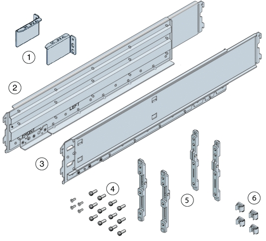
| Callout | Description |
|---|---|
|
1 |
Top rear braces that attach to the posts at the upper rear of the system. |
|
2 |
Left shelf rail. |
|
3 |
Right shelf rail. |
|
4 |
An assortment of M6 and 10-32 screws, including twelve M6 x 16 screws, twelve M6 x 12 screws, four M6 x 4 flathead screws, ten 10–32 screws, and twelve 10–32 shoulder screws. |
|
5 |
Two sets of four adapter brackets, one set for round-hole racks, and one set for square-hole racks. |
|
6 |
Four M6 cage nuts. Note - The cage nuts are not used. You can recycle them.
|
Staff, Tools, and Equipment Required to Rackmount the System
Caution:
Personal injury or equipment damage. Use a mechanical lift to install the system or follow the precautions in Removing Components to Reduce System Weight.Before starting the installation, gather the staff, tools, and equipment required to rackmount the system.
| Staff, Tools, and Equipment | Notes |
|---|---|
|
Four trained staff |
Four people are needed to lift or transport the system.
Note - If a mechanical lift is available or components have been removed from the system, it is safe for two people to lift or transport the system. |
|
No. 2 10-inch Phillips screwdriver |
A magnetic tip is recommended. |
|
Mechanical lift |
Strongly recommended. If not available, reduce the weight of the system. See Removing Components to Reduce System Weight.
|
|
Compatible four-post rack |
|
|
Rackmount kit |
|
|
Transportation kit |
|
|
Antistatic wrist strap and antistatic mat |
Required only if you remove system components. |
Removing Components to Reduce System Weight
Before installing Oracle Database Appliance Version 1 into a rack, you can remove components to reduce the weight of the system so that two persons can lift the system into the rack. Removing system components reduces the weight to approximately 96 pounds (43.5 kg).
Remove the following components to reduce the system weight:
-
Server nodes
-
Power supplies
Note:
Because of their light weight, you do not need to remove filler panels from the system.For instructions on removing components from the system and associated safety information, see the Oracle Database Appliance Service Manual.
Install Rackmount Hardware Into a Rack
Oracle Database Appliance Version 1 rack-mounting hardware consists of shelf rails, front and rear adapter brackets, rear braces, and screws.
Caution:
Personal injury or equipment damage. Use a mechanical lift to install the system, or follow the precautions in Removing Components to Reduce System Weight. Removing components reduces the weight from 160 pounds (72.6 kg) when fully loaded with components to approximately 96 pounds (43.5 kg).Caution:
Tip hazard. Always load equipment into a rack from the bottom up so that it does not become top-heavy and tip over. Deploy your rack’s anti-tilt bar to prevent the rack from tipping during installation.Caution:
Elevated operating ambient temperature. Install this equipment in an environment that does not exceed the maximum ambient temperature (Tma) specified in Environmental Specifications. If the system is installed in a closed or multi-unit rack assembly, then the operating ambient temperature of the rack environment might be greater than room ambient temperature.Caution:
Thermal damage. Install the equipment in a rack so that the airflow is not restricted.Caution:
Circuit overloading. Consider the connection of the equipment to the supply circuit and the effect that overloading of the circuits might have on overcurrent protection and supply wiring. Be aware of equipment nameplate power ratings when addressing this concern.Caution:
Equipment damage. Maintain reliable grounding of rack-mounted equipment. Pay attention to supply connections other than direct connections to the branch circuit (for example, use of power strips).- Use the Rackmount Guide and Alignment Template to measure the 4 rack unit (4RU) space in the rack where you will install the system.
Also, use that template to align the adapter brackets with the rack posts.
- Verify that you have a 4RU space in your rack.
Place the bottom edge of the Rackmount Guide and Alignment Template in the lowest available position in the rack. Align all arrows with holes on the rack post. Ensure that 4RU space is available in the rack.
- Select the adapter brackets that match your rack.
The system ships with two sets of adapter brackets: one set [1] for racks with square holes and one set [2] for racks with round holes.
The adapter brackets are labeled to indicate whether they are for square-hole racks or round-hole racks. Additionally, arrows on the adapter brackets indicate how they should be oriented. Install all brackets with the arrow labeled "Top" pointing up.
- Attach the adapter brackets to the front rack posts.
The following figure shows the front adapter brackets being attached to a square-hole rack [1] and a round-hole rack [2].
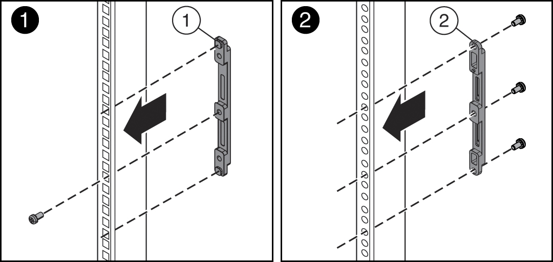
- Place the brackets so that the bracket is aligned with the 4RU space where the server will be installed, and verify that the arrow labeled "Top" on the brackets points up.
- Select the screws that match your rack.
-
For a square-hole rack, use one M6 x 12 mm screw per adapter bracket.
-
For a threaded round-hole rack, use three M6 x 12 mm screws, or three 10-32 shoulder screws per adapter bracket.
-
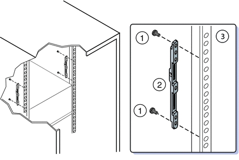
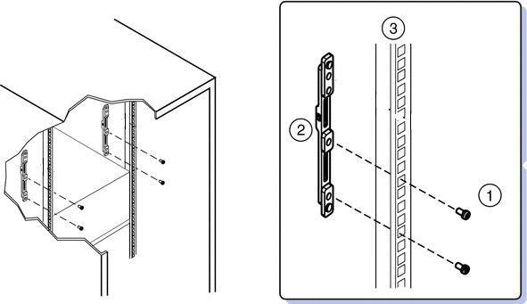
- Attach the adapter brackets to the rear rack posts.
- Place the brackets so that the bracket is aligned with the space where the server will be installed and verify that the arrow labeled "Top" on the brackets points up.
- Select the screws that match your rack.
-
For a square-hole rack, use two M6 x 12 mm screws per adapter bracket.
-
For a threaded round-hole rack, use two M6 x 12 mm screws or two 10-32 shoulder screws per adapter bracket.
The following figure shows the rear adapter brackets being attached to a round-hole rack.
The following figure shows the rear adapter brackets being attached to a square-hole rack.
-
- Attach rear braces to the rear rack posts and to the adapter brackets.
- Position the rear braces so that the tops of the braces [1] align with the 4U mark on each rear rack post.
- Install two M6 x 12 mm screws [3] or two 10-32 x 10 screws to attach each rear brace to the rack post and the adapter bracket.
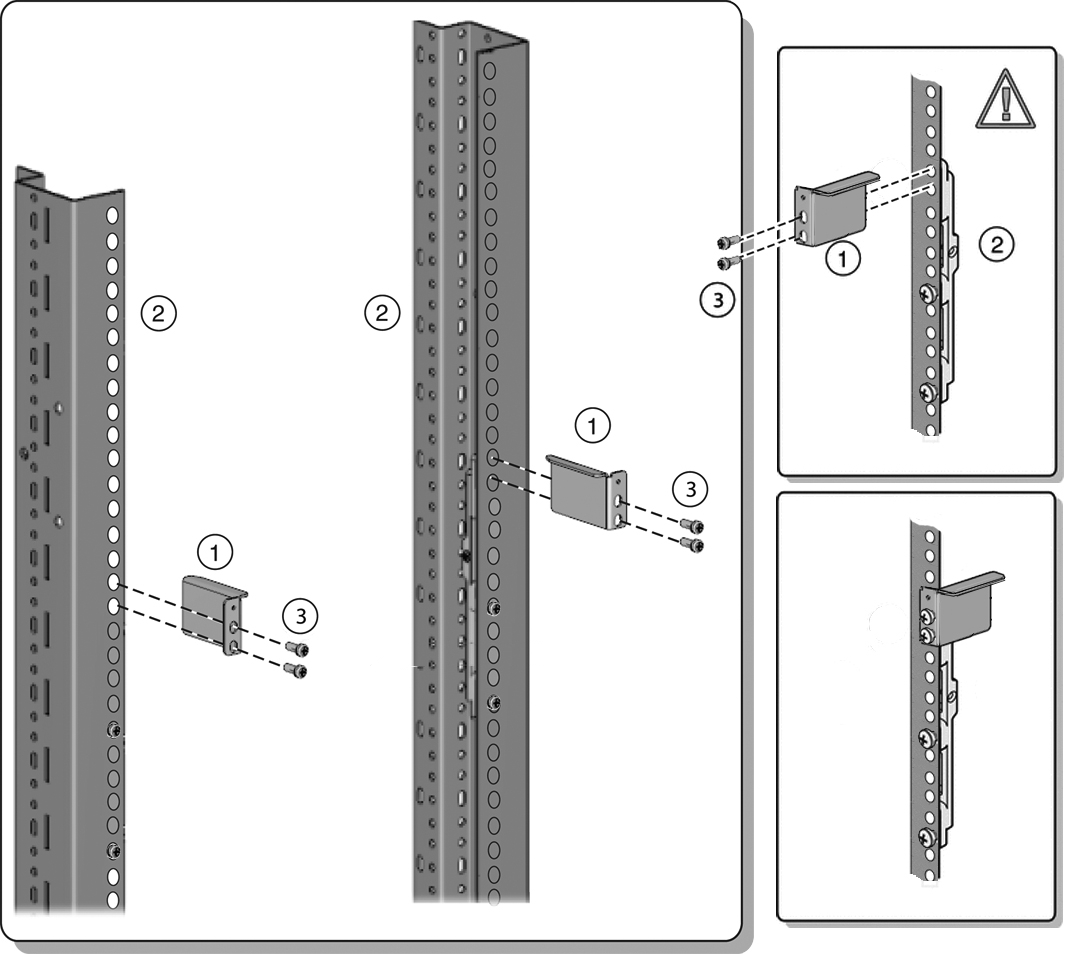
Note:
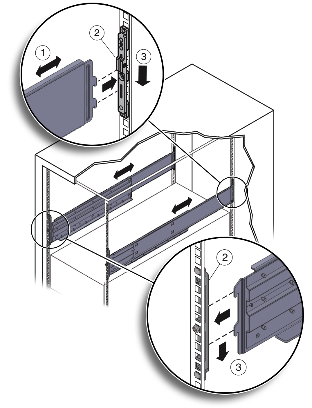
Before tightening the screws, slide the brackets [1] up as far as they will go. The holes on the brackets are oval-shaped so they can move up and down when the screws are loose. - Install the shelf rails into the rack.
Caution:
System failure. Orient the shelf rails properly, with the shelf facing inward and the gap toward the front of the rack; otherwise, the system might fall.- Expand the shelf rails [1] to fit between the front and rear rack posts.
- Insert the rear hooks of the shelf rails into the slots on the rear adapter brackets [2 and 3] first. Push down on the rail to engage the hooks.
- Insert the front hooks of the shelf rails into the slots on the front adapter bracket. Push down on the rails to engage the hooks.
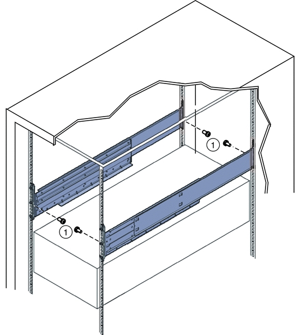
- Thread the four M4 x 10 flathead locking screws into the four adapter brackets [1]).
These screws prevent the shelf rails from accidentally lifting out of the adapter brackets.
See also
Install the System Into a Rack
Install the System Into a Rack
Before You Begin
Before you begin installing your Oracle Database Appliance Version 1 into a rack, perform the steps in Install Rackmount Hardware Into a Rack.
- Raise the system to slightly above the shelf surfaces.
Use a mechanical lift if possible.
Caution:
Personal injury or equipment damage. Use a mechanical lift to install the system, or follow the precautions in Removing Components to Reduce System Weight. Removing components reduces the weight from 160 pounds (72.6 kg) when fully loaded with components to approximately 96 pounds (43.5 kg).Caution:
Tip hazard. Always load equipment into a rack from the bottom up so that it does not become top-heavy and tip over. Deploy your rack’s anti-tilt bar to prevent the rack from tipping during installation. - Slide the system onto the shelf rails until the rack-mounting ears contact the rack post. Adjust the top rear braces to fully insert the system.
Caution:
Drop Hazard. Do not release the system until it is more than 12 inches (305 mm) into the rack, and is firmly supported by the shelf rails. The shelf rails do not safely support the system until it is more than 12 inches (305 mm) inside the rack.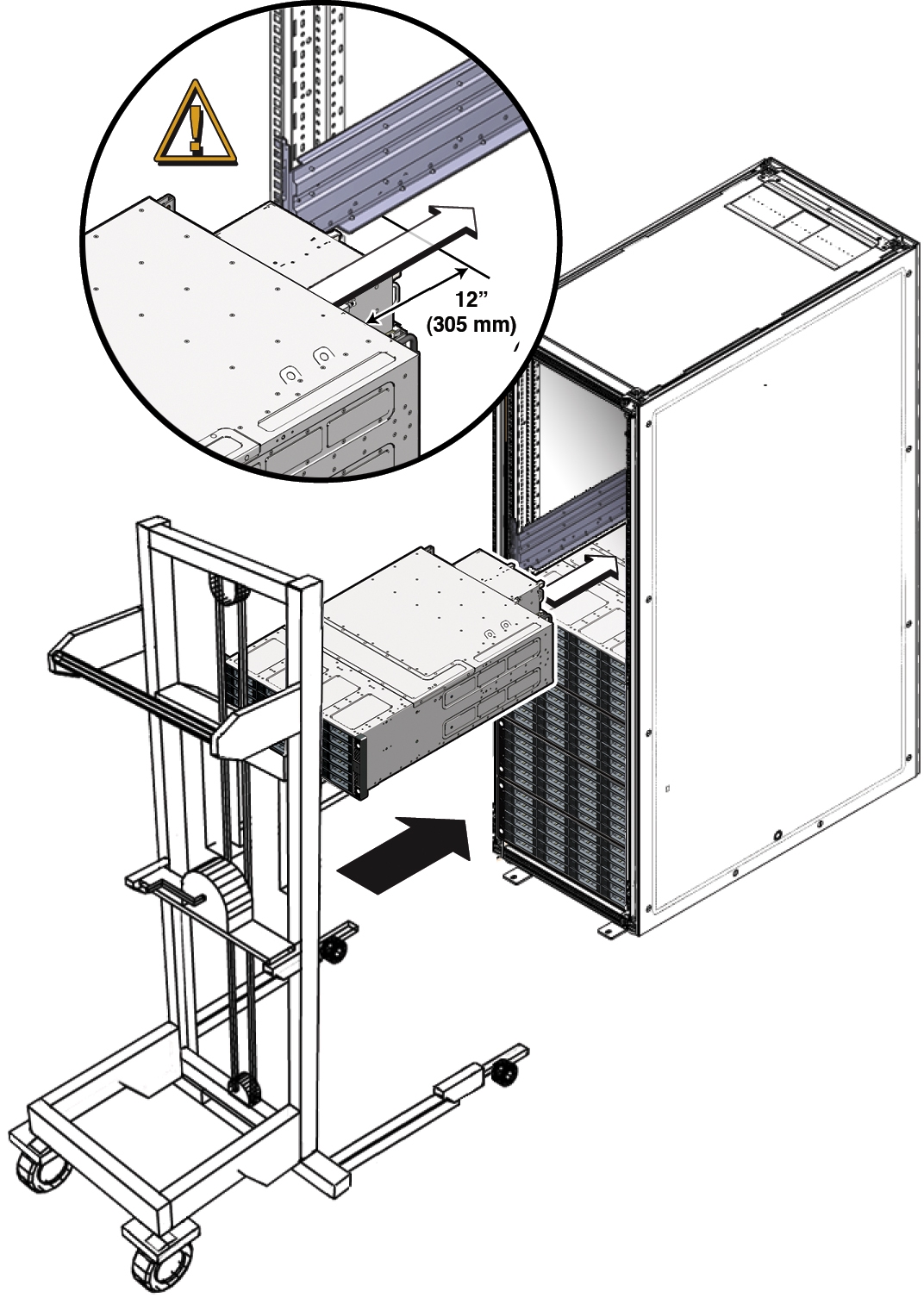
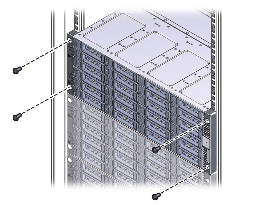
- Use four screws to attach the front of the system to the front of the rack.
-
On a threaded, round-hole rack, use four M6 x 12 mm screws or four 10-32 x 10 mm screws.
-
On a square-hole rack, use four M6 x 16 mm screws.
Note:
On square-hole racks, the screws pass through the rack and thread into the adapter bracket. On round-hole racks, the screws thread into the rack rails.
-
- To adjust the rear braces, do the following:
- If you removed components from the system, replace them.
For instructions, see the Service Manual, which is part of the product documentation.
Installing Shipping Brackets
This section includes the following information about installing the shipping brackets for Oracle Database Appliance Version 1:
-
If you plan to ship the system in a rack to another destination, see Install Shipping Brackets.
-
If your system is shipped to you in a rack, you must remove the shipping brackets before placing the system into service. For instructions, see the Oracle Database Appliance Service Manual.
Transportation Kit Contents
The following figure shows the hardware that is included in the Oracle Database Appliance Version 1 transportation kit.
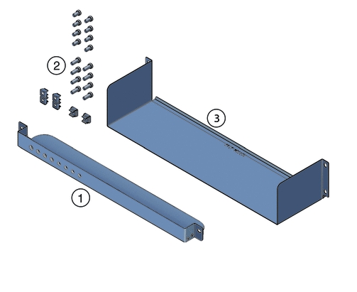
| Callout | Description |
|---|---|
|
1 |
Front shipping bracket. |
|
2 |
Screws and cage nuts: For the rear shipping bracket:
|
|
3 |
Rear shipping bracket. |
Install Shipping Brackets
If you plan to move or ship Oracle Database Appliance Version 1 in a rack to another location, you need to install the shipping brackets.
- Remove the two short screws that fasten the bottom of the system to the rack.
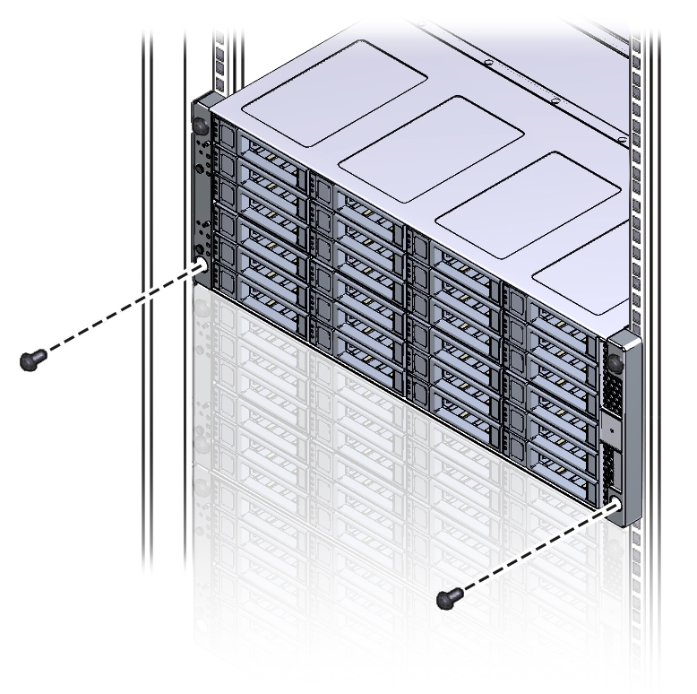
- Insert the front shipping bracket [2] under the front of the system with the supporting flange underneath the system.
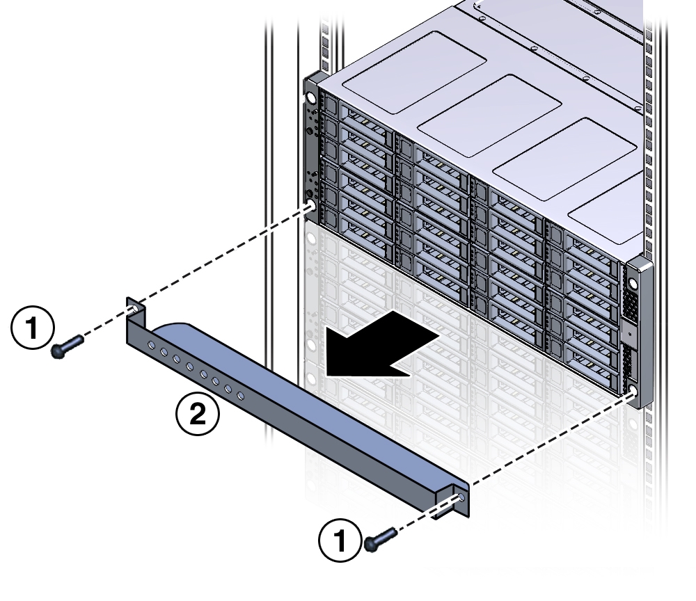
- Use the two long screws (either the M6 x 30 mm screws or the 10-32 x 1.25 inch screws) [1] to fasten the shipping bracket [2] to the front of the system.
Tighten the two long screws to secure the shipping bracket and the system to the rack.
Note:
The front shipping bracket includes eight threaded holes used for storing unused screws. When the shipping brackets are not installed, the front shipping bracket holds the long screws used to install them. When the shipping brackets are installed, it stores the short screws that were used to secure the system to the front of the rack before the front shipping bracket was installed. - Insert the short screws into the four empty storage holes on the front shipping bracket.
Store the screws so they can be used when the shipping bracket is removed.
- Remove the bottom two screws that hold the rear adapter brackets in place.
Caution:
Equipment damage. Do not remove the bottom screws unless you are certain that at least one upper screw is in place; otherwise, the system might fall. - Insert the rear shipping bracket [2] under the back of the system with the side panels facing up.
Use four screws [1] (either the M6 x 16 mm screws or the 10-32 x 10 mm screws) to fasten the rear shipping bracket to the rack. Do not finish tightening these screws. The screws should be tight enough to hold the bracket in place, but you should still be able to move the bracket slightly.
The bracket should be fastened to the posts, but loose enough to move slightly.
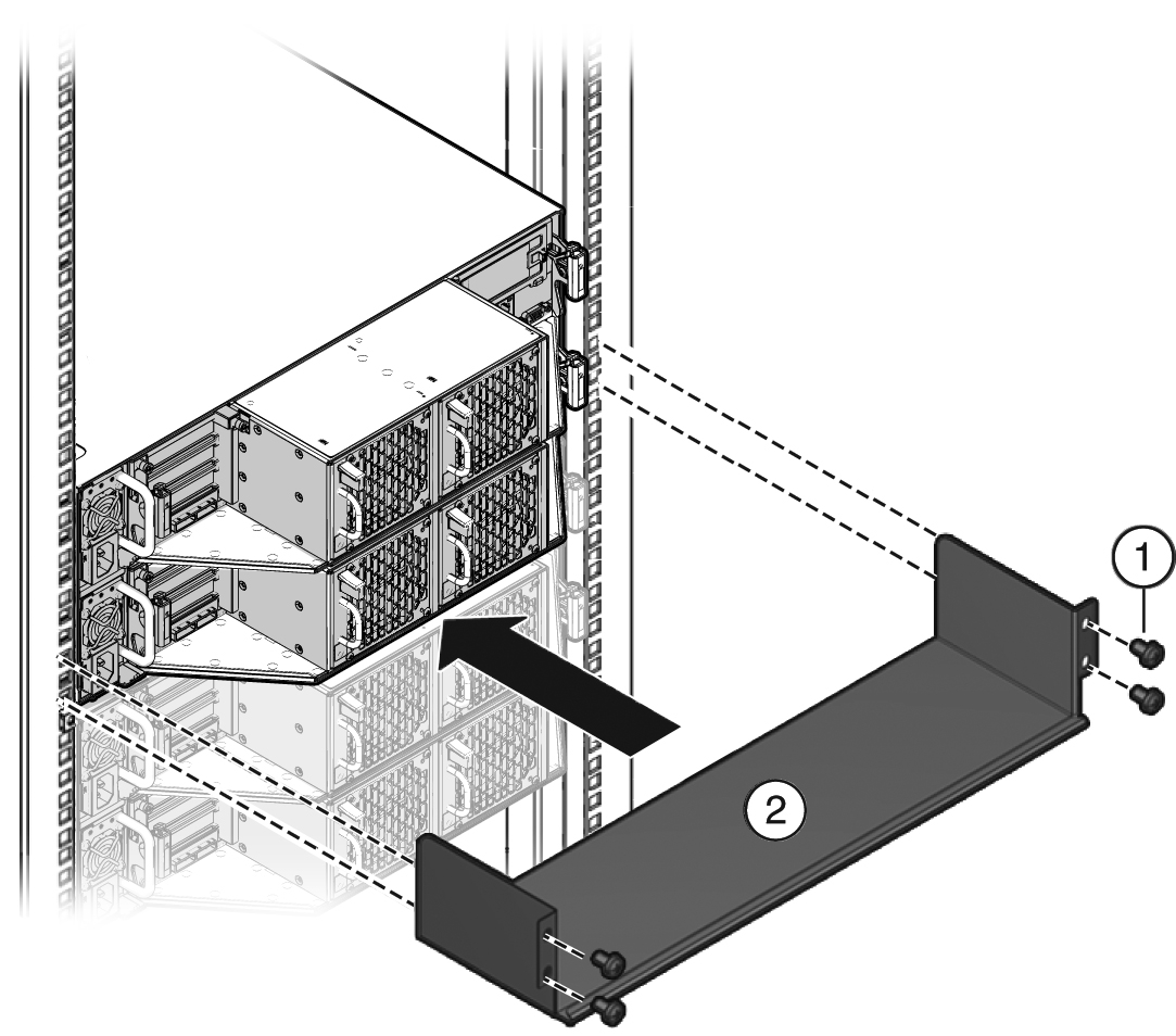
- Lift the rear shipping bracket up so that it rests firmly against the bottom of the system, then finish tightening the screws that hold the bracket in place.
If necessary, loosen the screws enough so that you can move the bracket, then push the bracket against the bottom of the system and tighten the screws.
Caution:
Equipment damage. To prevent damage to the system during shipping, the bottom shipping bracket must be positioned firmly against the bottom of the system.
