10g (9.0.4)
Part Number B12121-01
Home |
Solution Area |
Contents |
Index |
| Oracle® Application Server ProcessConnect User's Guide 10g (9.0.4) Part Number B12121-01 |
|
This chapter describes how to create integration modeling metadata with the assistance of the Oracle Application Server ProcessConnect modeling wizards.
This chapter contains these topics:
"Business Process and Role Creation Methods" for recommendations on when to create modeling metadata automatically with the wizards or manually
See Also:
The Oracle Application Server ProcessConnect user interface tool provides several modeling wizards that enable you to create modeling metadata. Before using these wizards, it is important to understand several key modeling wizard concepts:
Chapter 3, "Oracle Application Server ProcessConnect Concepts" for additional details about modeling metadata
See Also:
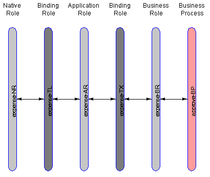
A single spoke consists of a role set extending from the native role to the business process. Role ports and data flow connect the role set together. A native role can belong to only a single spoke. This means that a spoke is uniquely identified by its native role. Figure 9-1 shows an Integration Diagram of a single spoke with the expense-NR native role.
|
See Also:
"Viewing an Integration Diagram" for instructions on viewing an Integration Diagram |
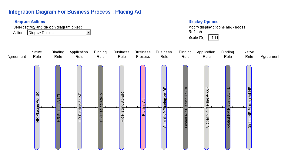
Multiple spokes connected by a single business process comprise an integration. A business process uniquely identifies an integration. The business process resides in the middle to connect all spokes in an integration. Figure 9-2 shows a single business process (Placing Ad) connecting two spokes. Each spoke has its own native role (HR Placing Ad-NR and Global NP Placing Ad-NR).
Spokes consist of two types:
See Also:
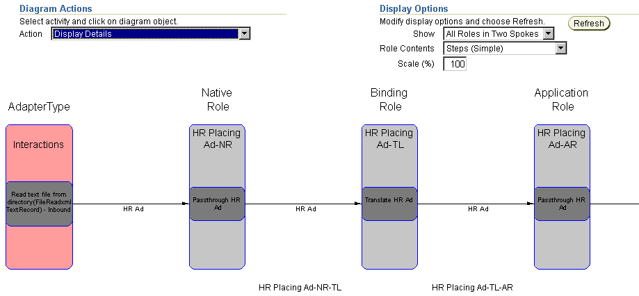
An event flow is the complete path a single event takes through a spoke. An inbound event flow begins with an inbound interaction that produces an inbound native event. As the event flows from the native role to the business process, the native event is translated to an application event and the application event is transformed to a business event. An outbound event flow takes an event in the opposite direction, going from a business event in a business process to an outbound interaction bound to the native role.
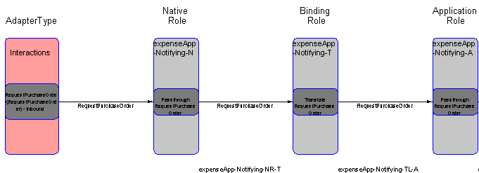
Figure 9-3 shows a portion of the event flow in a spoke. The Event Flow Diagram shows the events and the role steps that process and pass the events (HR Ad in this example) through a spoke.
|
See Also:
"Viewing an Event Flow Diagram" for instructions on viewing an Event Flow Diagram |
This section describes the four modeling wizards that enable you to create modeling metadata.
These modeling wizards provide different types of functionality:
This section contains these topics:
The Create End-to-End Basic Integration wizard creates two spokes (with a new business process in the middle) and a single event flow that extends from the initiating spoke's native role to the invoked spoke's native role. Additional (end-to-end) event flows can be added with the Add End-to-End Basic Event Flow wizard. There are no options for selecting existing business events or transformation maps. All metadata is newly created.
The business event names generated are the same as the application event that is associated with the inbound interaction and native event selected. If this name matches an existing business event, the existing business event is used. The Create End-to-End Basic Integration wizard also uses an existing transformation map if there is a map that uses the same application event and business event as source and target parameters.
Figure 9-4 shows all the roles in an integration between two spokes.
|
See Also:
"Creating Two Spokes" to use the Create End-to-End Basic Integration wizard |
The Add End-to-End Basic Event Flow wizard adds an additional event flow to two spokes extending from the native role in the initiating spoke to the native role in the invoked spoke. These two spokes and initial event flow are typically created with the Create End-to-End Basic Integration wizard. There are no options for selecting existing business events or transformation maps. In this case, all metadata is newly created.
You can also use the Add End-To-End Basic Event Flow wizard to add an event flow to two spokes that were created manually without the Create End-to-End Basic Integration wizard. In this case, ensure that both spokes are completely created before you use the Add End-to-End Basic Event Flow wizard. (that is, all roles and data flow groups connecting them are completely created). Otherwise, errors occur when you attempt to add event flow with the Add End-To-End Basic Event Flow wizard.
All generated pass-through, transformation, translation, and SetParty steps appear at the bottom of each role's Process Diagram with a control flow from the previous last step and another control flow to the end step.
The business event names generated are the same as the application event that is associated with the inbound interaction and native event selected. If this name matches an existing business event, the existing business event is used. The Add End-to-End Basic Event Flow wizard also uses an existing transformation map if there is a map that uses the same application event and business event as source and target parameters.
Figure 9-5 shows three roles in an event flow before running the Add End-To-End Basic Event Flow wizard.
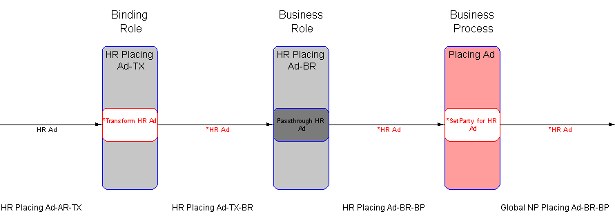
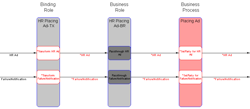
Figure 9-6 shows the same roles in the event flow after running the wizard. A second event flow is added.
|
See Also:
"Adding Event Flow to Two Spokes" to use the Add End-to-End Basic Event Flow wizard |
The Create Spoke wizard creates a single spoke (extending from the native role to the business process) and a single event flow. This single spoke can be created for use in several places, including the following:
Additional event flows can be added to this single spoke with the Add Event Flow wizard. This wizard performs the following tasks based on input you provide:
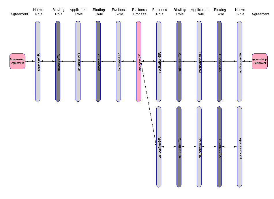
When the business role ports are data flow-bound to ports on an existing business process, all unbound business process ports are searched for a correct match in event type and direction. If one exists, it is used. If one does not exist, a new business process port is created (and also a pass-through step and port with the opposite flow). If multiple ports match, the first matching unbound port is used. Figure 9-7 shows the third spoke that is added to an end-to-end basic integration.
|
See Also:
"Creating a Single Spoke" to use the Create Spoke wizard |
The Add Event Flow wizard adds an additional event flow to a single spoke extending from the native role to the business process. This wizard performs the following tasks based on input you provide:
The event flow is added to the single spoke shown in the lower portion of Figure 9-7.
When the business role ports are data flow-bound to ports on an existing business process, all unbound business process ports are searched for a correct match in event type and direction. If one exists, it is used. If one does not exist, a new business process port is created (and also a pass-through step and port with the opposite flow). If multiple ports match, the first matching unbound port is used.
|
See Also:
"Adding Event Flow to a Single Spoke" to use the Add Event Flow wizard |
This section describes several features common to all wizards:
You can view diagrams that show various stages of modeling wizards design. Modeling metadata that is incomplete and requires you to perform additional steps outside the modeling wizards is highlighted in red in all diagrams.
"Viewing the Metadata Modeling Diagrams" for a detailed description of the tasks you can perform with the modeling metadata diagrams
See Also:
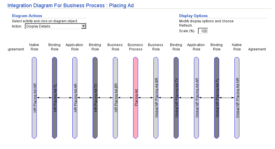
Figure 9-8 shows an Integration Diagram, which identifies each role in the end-to-end integration. Click a specific role to view its steps in an Event Flow Diagram.
|
See Also:
"Viewing an Integration Diagram" for instructions on viewing an Integration Diagram |
Figure 9-9 shows a portion of the Event Flow Diagram, which identifies the events and role steps that process and pass the events through the two spokes of the end-to-end basic integration.
|
See Also:
"Viewing an Event Flow Diagram" for instructions on viewing an Event Flow Diagram |
The Event Flow Diagram includes three selections available from the Role Contents list under the Display Options section. (See Figure 9-13.)
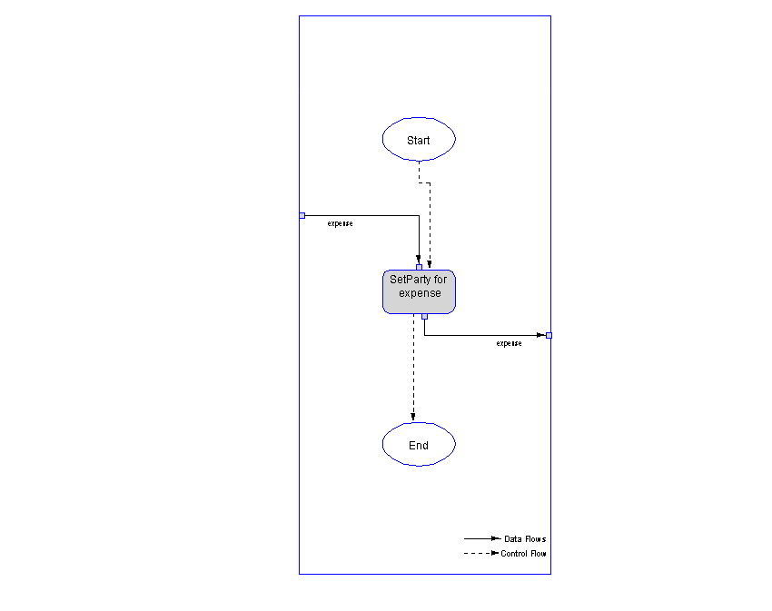
Each business process or role has a Process Diagram. Figure 9-10 shows a Process Diagram for a specific role or business process of the end-to-end basic integration. The Process Diagram identifies the events, steps, control flows, and data flows.
|
See Also:
"Viewing a Process Diagram" for instructions on viewing a Process Diagram |
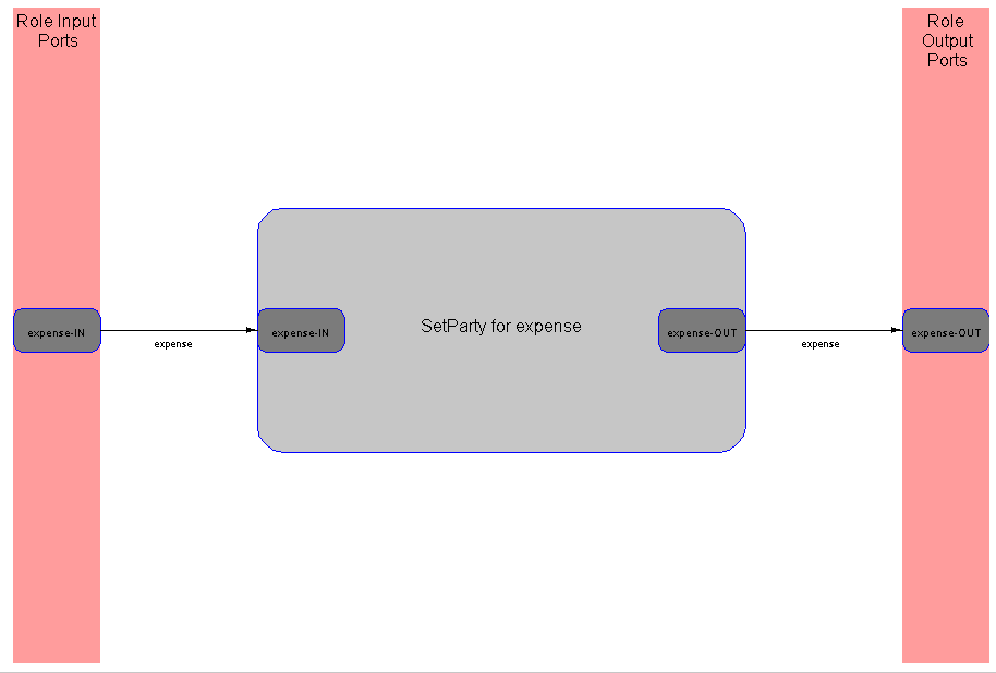
Figure 9-11 shows a Step Binding Diagram.
|
See Also:
"Viewing a Step Binding Diagram" for instructions on viewing a Step Binding Diagram |
If you select an outbound interaction that includes both an inbound request and an outbound response, you are prompted for additional information for handling the response. For the two End-To-End wizards, when one spoke has a response, you are prompted to select another interaction to handle the response at the other spoke. For the Create Spoke and Add Event Flow wizards, if there is a response, then you are prompted to create (or select existing) business events and transformation maps for both the request and the response event flows. Optionally, you can click the ignore box to specify that the response native event must be consumed in the inbound native role (preventing further processing from occurring). In this case, there is no event flow for the response.
Names are created that are not always unique. In some cases, you receive an error. For example, if a generated role name already exists, you must enter a different name in the Role Naming Convention field. In other cases, the name is made unique by appending a sequence number to the end. For example, if an event named ack flows multiple times in the same spoke, there are multiple role ports with the generated name of ack-OUT. The wizards make the port names unique by appending a sequence number, such as ack-OUT1 or ack-OUT2.
The modeling wizards only list interactions for selection that are defined as complete. Incomplete interactions do not have a record type or have a record type that is not associated with a native event type or a native event that is not associated with an application event. The modeling wizards do not list these interactions.
Ensure that you add the adapter interactions you want to use before using these wizards. The interactions are then selectable in the wizard pages. Interactions represent unique actions that can be performed with a specific adapter (such as requesting a purchase order, confirming a purchase order, and so on).
Ensure that you also create a native event for the interaction and specify a translator. You can perform this task either during or after you add an adapter interaction.
|
See Also:
|
Table 9-1 describes the locations from which the modeling wizards can be started.
Use the Create End-To-End Basic Integration wizard to create two spokes.
The Create End-To-End Basic Integration page appears.
The page refreshes to display the native event associated with this interaction.
The page refreshes to display the native event associated with this interaction.
If you select an outbound interaction that includes both an outbound request and an inbound response, the page refreshes and prompts you to enter an additional interaction.
Use the Add End-To-End Basic Event Flow wizard to add additional event flow to two spokes.
The Add End-To-End Basic Event Flow page appears.
The page refreshes to display the native event associated with this interaction.
The page refreshes to display the native event associated with this interaction.
If you select an outbound interaction that included both an outbound request and an inbound response, the page refreshes and prompts you to enter an additional interaction.
If the business event and transformation map names to be used exist, they are included in the spoke.
Use the Create Spoke wizard to create a single spoke. This single spoke can be created for use in several places, including the following:
The Create Spoke: Business Process page appears.
| To... | Then... |
|---|---|
|
Create a new business process |
|
|
Use an existing business process |
The Create Spoke: Interactions page appears.
The Create Spoke: Roles page appears.
The Create Spoke: Events page appears.
| To... | Then... |
|---|---|
|
Create a new business event |
|
|
Use an existing business event |
If you selected an outbound interaction in Step 4 that included both an outbound request and an inbound response, you are prompted to create business events for both.
The Create Spoke: Transformations page appears.
| To... | Then... |
|---|---|
|
Create a new transformation map |
|
|
Use an existing transformation map |
For an inbound event flow, the list of existing transformation maps includes only maps that have the application event as the source parameter and the business event as the target parameter. For an outbound event flow, the list of existing transformation maps includes only maps that have the business event as the source parameter and the application event as the target parameter.
If you selected an outbound interaction in Step 4 that included both an outbound request and an inbound response, you are prompted to create transformation maps for both.
You can create additional event flows for an existing single spoke.
The Add Event Flow: Interaction page appears.
The Add Event Flow: Events page appears.
| To... | Then... |
|---|---|
|
Create a new business event |
|
|
Use an existing business event |
If you selected an outbound interaction in Step 4 that included both an outbound request and an inbound response, you are prompted to create business events for both.
The Add Event Flow: Transformations page appears.
| To... | Then... |
|---|---|
|
Create a new transformation map |
|
|
Use an existing transformation map |
For an inbound event flow, the list of existing transformation maps includes only maps that have the application event as the source parameter and the business event as the target parameter. The application event is associated with the native event. The native event is associated with the record type that is associated with the chosen interaction.
For an outbound event flow, the list of existing transformation maps includes only maps that have the business event as the source parameter and the application event as the target parameter.
If you selected an outbound interaction in Step 4 that included both an outbound request and an inbound response, you are prompted to create transformation maps for both.
The review page displays details about the type of modeling metadata for the wizard to create. Figure 9-12 provides an example of the type of information that displays for the review page of the Create End-To-End Basic Integration wizard.
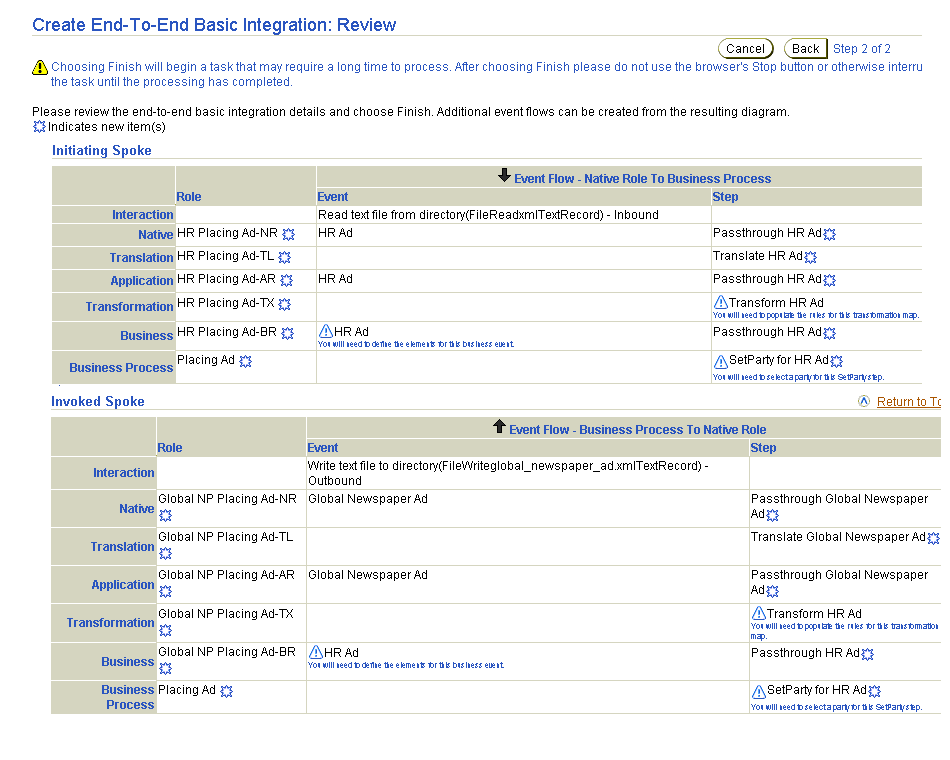
Table 9-2 describes the review page sections shown in Figure 9-12.
Table 9-2 Wizard Review Page
Table 9-3 through Table 9-5 provide additional details about the naming conventions for the modeling metadata to create.
Roles names are appended with the suffixes shown in Table 9-3. These details also display in the review page shown in Figure 9-12.
| For Role... | Suffix Is... | For Role... | Suffix Is... |
|---|---|---|---|
|
Native role |
-NR |
Transformation binding role |
-TX |
|
Translation binding role |
-TL |
Business role |
-BR |
|
Application role |
-AR |
|
|
Data flow groups are appended with the suffixes shown in Table 9-4.
Port, step, and events follow the naming conventions shown in Table 9-5.
If event flow creation is successful, the Event Flow Diagram appears (in this example, the Event Flow Diagram that shows modeling metadata created by the Create End-to-End Basic Integration wizard). The Event Flow Diagram is very large. For this reason, it is broken down into four diagrams, as show in Figure 9-13 through Figure 9-16.


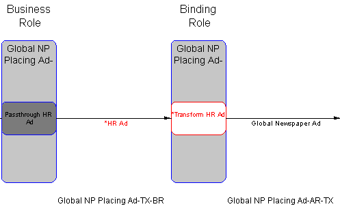
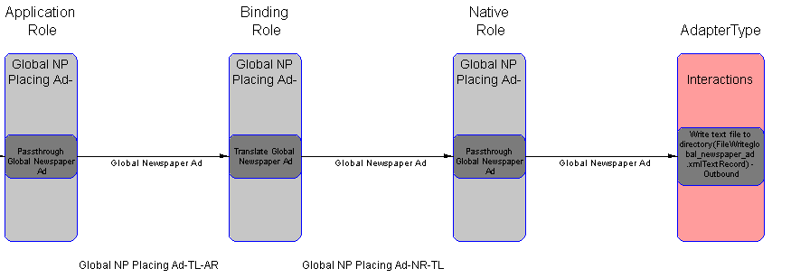
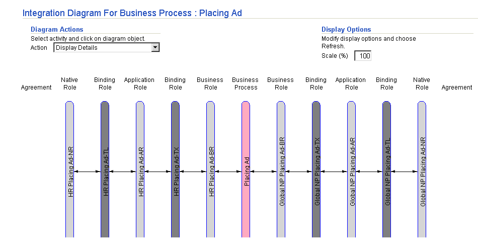
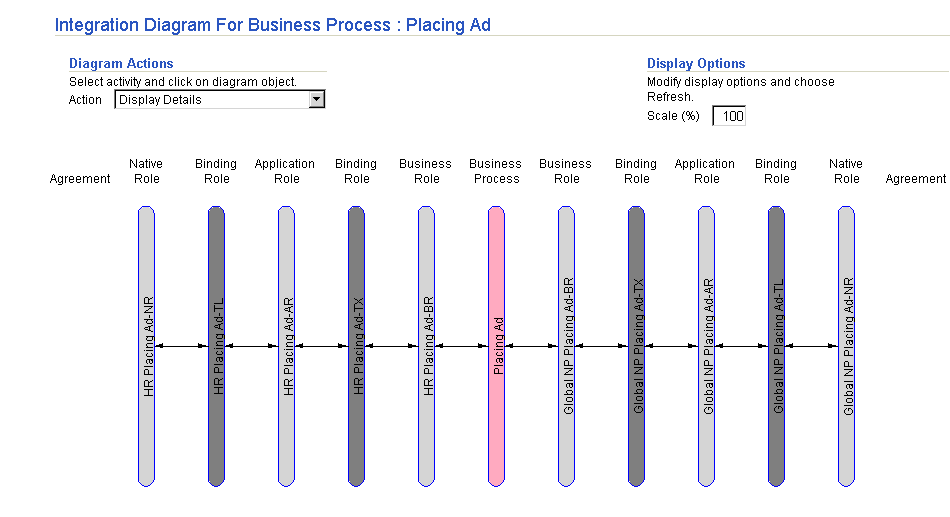
Figure 9-17 shows the Integration Diagram of the two spokes created by the Create End-to-End Basic Integration wizard. The Agreement header displays for both native roles. When you add the native role of a spoke to an agreement, an Agreement icon displays beneath the Agreement header. You can click this icon to display the details page for the agreement.
|
See Also:
"Viewing an Integration Diagram" for details about the Agreement icon that displays beneath the Agreement header |
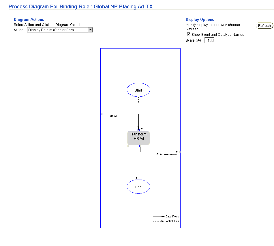
Figure 9-18 shows the Process Diagram of a role created by the Create End-to-End Basic Integration wizard. For this example, one of the transformation binding roles and its transformation step are shown.
After wizard creation, you must complete several additional steps to make your modeling metadata valid. You can also customize your modeling metadata by creating additional steps, ports, data flows, and control flows.
This section contains these topics:
Create event body elements for business events created by the wizards. You can access the page for creating event body elements in either of two ways:
Define transformation rules for event transformation maps created by the wizards. You can access the page for creating event transformation maps in either of two ways:
You can customize your modeling metadata by manually creating additional steps, ports, data flows, and control flows.
Events originate from parties and are sent to parties. At some point in event processing, event addressing must be performed. Event addressing enables you to update the SetParty step with the target party with which to integrate. You can access the page for updating the target party in the SetParty step in either of two ways:
Follow these instructions to delete a spoke.
This section describes common modeling wizard user errors.
The most common user error is using the wrong wizard. Specifically, you attempt to use the Create End-To-End Basic Integration wizard when you really want to add a spoke or an event flow to an existing business process.
The Create End-To-End Basic Integration wizard always creates a new integration, including a new business process. If you attempt to specify an existing business process, the Create End-To-End Basic Integration wizard tries to create a new business process with the same name and you get a UNIQUE CONSTRAINT VIOLATION error.
Error : There was an error creating the business process.
Error -: AIP-16012: Parameter: owning Composite Step is unique for object
Composite Step OwningCompositeStep.CompositeStep -

Error -: AIP-11052: Writing following objects: Composite Step failed due to
following constraint violation: COMPOSITESTEP_UK. UNIQUE CONSTRAINT VIOLATION
Name -

Error -: AIP-11052: Writing following objects: Composite Step
failed due to following constraint violation: COMPOSITESTEP_UK. UNIQUE
CONSTRAINT VIOLATION
The first error line is from the wizard, which identifies what it was doing at the time of the error. The two errors following that one are what the repository reports.
A similar problem occurs when you specify a role naming convention that was already used in another integration. This results in the wizard creating duplicate role names. You see the following error:
Error : There was an error creating native role bp1in-NR .
Error -: AIP-16012: Parameter: owning Composite Step is unique for object
Composite Step
OwningCompositeStep.CompositeStep -
Error -: AIP-11052: Writing following objects: Composite Step failed due to
following constraint violation: COMPOSITESTEP_UK. UNIQUE CONSTRAINT VIOLATION
Name -
Error -: AIP-11052: Writing following objects: Composite Step failed due to
following constraint violation: COMPOSITESTEP_UK. UNIQUE CONSTRAINT VIOLATION
This chapter describes how to use the modeling wizards. With the modeling wizards, you can perform the following tasks:
|
|
 Copyright © 2003 Oracle Corporation. All Rights Reserved. |
|