10g (9.0.4)
Part Number B12121-01
Home |
Solution Area |
Contents |
Index |
| Oracle® Application Server ProcessConnect User's Guide 10g (9.0.4) Part Number B12121-01 |
|
This chapter describes the business process and role management tasks required to design an integration. This chapter contains these topics:
"Modeling Metadata Design" for conceptual details about business processes, role types, ports, data flows, steps, and control flows
See Also:
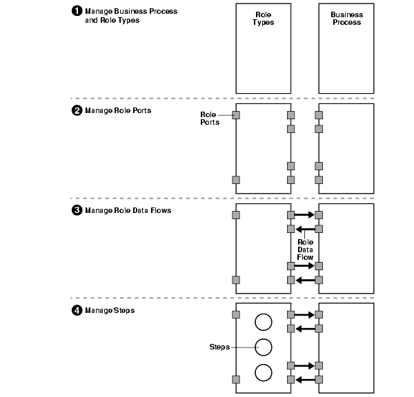
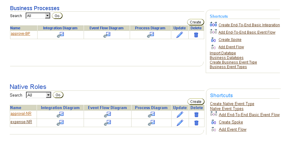
The Oracle Application Server ProcessConnect user interface tool enables you to perform the business process and role management tasks required for integrations. These tasks consist of managing the components in Figure 12-1 and Figure 12-2.

After design is complete and the integration is deployed, these components enable the business process to be executed and events to flow from role to role.
Table 12-1 describes each component shown in Figure 12-1 and Figure 12-2 and provides references for more information. You must perform these tasks to define the role type and business process portions of an integration.
The Oracle Application Server ProcessConnect user interface tool enables you to perform the management tasks shown in Figure 12-1 and Figure 12-2 and described in Table 12-1. Figure 12-3 through Figure 12-5 provide a high-level overview of the location of these management tasks within the Oracle Application Server ProcessConnect user interface tool, with references provided to the management task key number shown in Table 12-1. The locations of these management tasks are described in detail throughout this chapter.
Figure 12-3 displays the business process and role management tasks identified by key number one in Figure 12-1.
The upper page of Figure 12-4 displays the data port, data flow group, and step management tasks identified by key numbers two, three, and four, respectively, in Figure 12-1. The lower page of Figure 12-4 displays the step port and step control flow management tasks identified by key numbers five and seven, respectively, in Figure 12-2.
Figure 12-5 displays the step data flow management tasks identified by key number six in Figure 12-2.
The Oracle Application Server ProcessConnect user interface tool provides two methods for creating business process and role modeling metadata:
Select a creation method based on your level of modeling metadata design expertise and the needs of your environment. A common method is to first use the modeling wizards to create the modeling metadata, including the business process and roles with default steps, ports, and data flows. You can then manually modify and create additional modeling metadata to add more complex processing.
|
See Also:
|
The Oracle Application Server ProcessConnect user interface tool includes several modeling metadata diagrams that provide a graphical view of your integration. As you create, update, or delete modeling metadata, these diagrams are updated to reflect your changes. Oracle recommends that you view these graphics frequently when creating or changing modeling metadata for an integration. Table 12-2 lists these diagrams and the locations from which they can be accessed. When you access these diagrams, additional options are provided for accessing more detailed graphical views of modeling metadata, and for creating, updating, and deleting modeling metadata.
| Accessible From... | Integration Diagram | Process Diagram | Event Flow Diagram | Step Binding Diagram | See... |
|---|---|---|---|---|---|
|
Diagram columns at top of Business Processes page |
Yes |
Yes |
Yes |
No |
Upper page of Figure 12-15 |
|
Diagram columns at top of type Roles page where type is either Native, Application, Business, or Binding |
Yes |
Yes |
Yes |
No |
Upper page of Figure 12-16 |
|
Links at bottom of Business Process Details : name page where name is the business process name |
Yes |
Yes |
Yes |
No |
Lower page of Figure 12-15 |
|
Links at bottom of type Role Details : name page |
Yes |
Yes |
Yes |
No |
Lower page of Figure 12-16 |
|
Links at bottom of Data Port Details : name page (for role ports) |
No |
Yes |
Yes |
No |
Lower page of Figure 12-17 |
|
Links at bottom of Data Flow Group Details : name page |
Yes |
No |
Yes |
No |
|
|
Links at bottom of Step Details : name page |
No |
Yes |
Yes |
Yes |
|
|
Links at bottom of Data Port Details : name page (for step ports) |
No |
Yes |
Yes |
Yes |
Follow these instructions to access the metadata modeling diagrams:
| To View a... | Select the... | Go To Step... |
|---|---|---|
|
Business Process |
Business Processes tab to access the Business Processes page |
|
|
Role |
Roles tab to access the Business Roles page |
See the following sections for details about the diagram type you selected:
Follow these instructions to view an Integration Diagram:
To view an Integration Diagram:
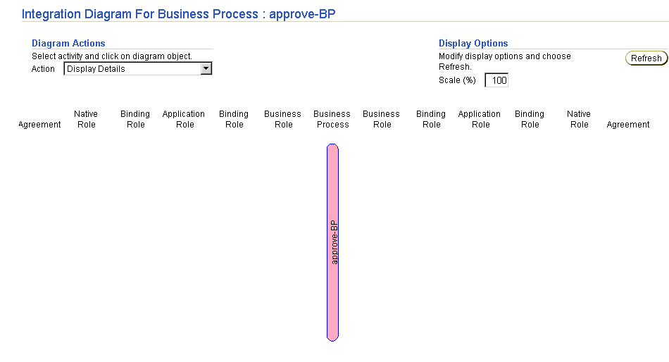
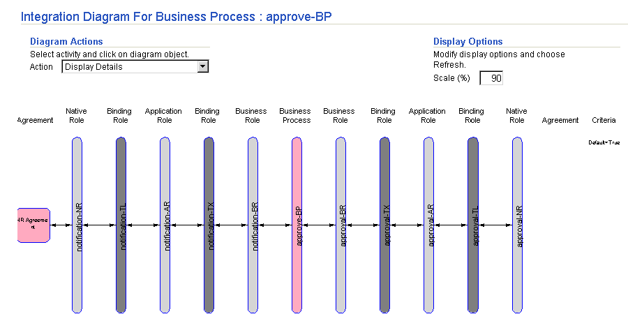
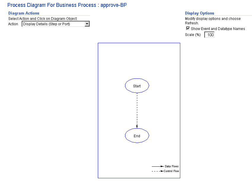
The Integration Diagram displays the selected business process or role. Figure 12-6 shows the Integration diagram for the approve-BP business process early in the design stage.
As you add additional roles, these changes are reflected in the Integration Diagram. For example, creating two spokes of roles, role ports, data flows, steps, step ports, and control flow with the business process approve-BP in the middle causes the changes shown in Figure 12-7 to display in the Integration Diagram.
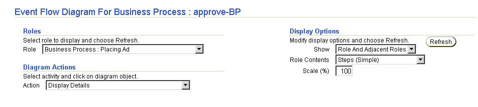
Follow these instructions to view an Event Flow Diagram:
To view an Event Flow Diagram:
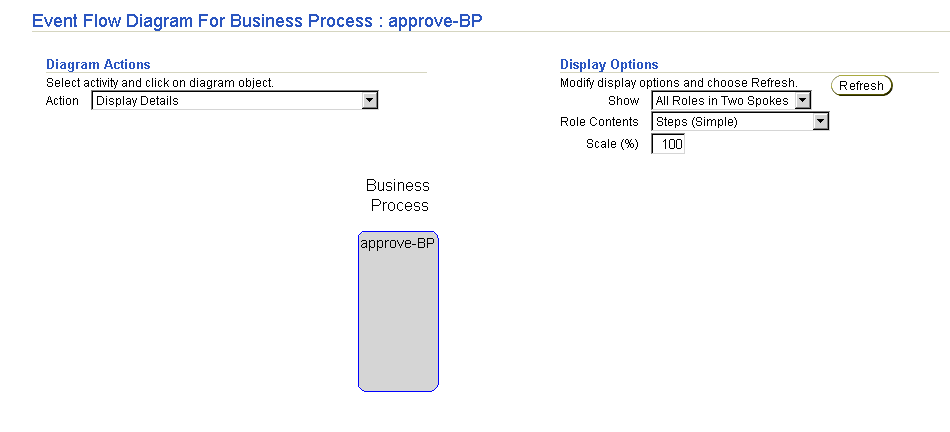
The Event Flow Diagram displays the selected business process or role. Figure 12-8 shows the Event Flow diagram for the approve-BP business process early in the design stage.
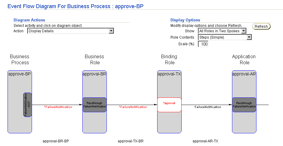
As you create additional roles and role steps, these changes are reflected in the Event Flow Diagram. For example, if you perform the following tasks:
These tasks cause the changes shown in Figure 12-9 to display in the Event Flow Diagram. Incomplete modeling metadata displays in red, such as a business event with no event body element or a transformation step with no defined event transformation maps. You must complete this modeling metadata before it can be included in a deployed configuration.
The Event Flow Diagram refreshes to display the Spoke (left side) and Spoke (right side) lists.
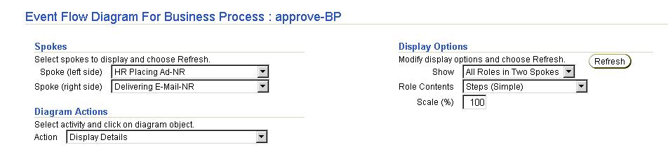
Both lists display the same native roles of the current business process.
The Event Flow Diagram refreshes to show the two selected spokes.
Follow these instructions to view a Process Diagram:
To view a Process Diagram:
When fully created, the Process Diagram displays events, steps, ports, data flows, and control flows for the selected business process or role. Figure 12-10 shows the Process Diagram for the approve-BP business process early in design.
As you add steps, ports, data flows, and control flows to the business process or role, these changes are reflected in the Process Diagram. Unbound step and role ports for which data flow is not yet defined (such as return code ports of transformation, translation, or condition steps) appear. For example, creating the SetParty step, role data flows, step data flows, control flows, and events causes the changes shown in Figure 12-11 to display in the Process Diagram.
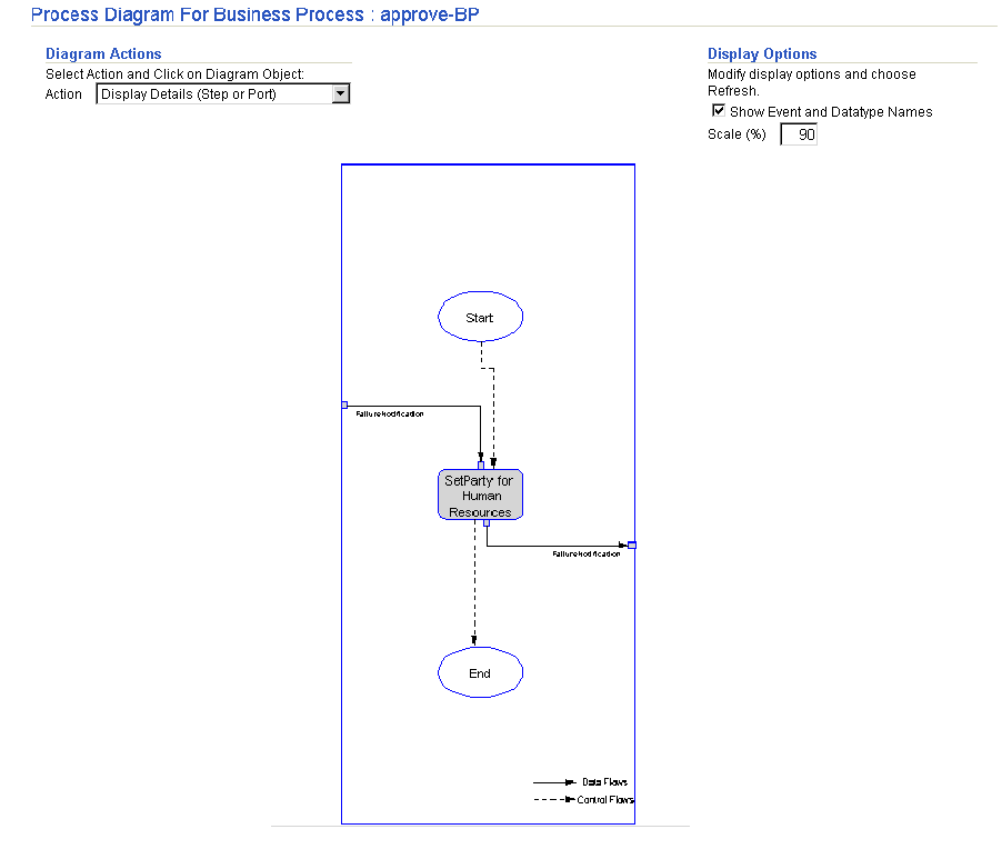
Incomplete modeling metadata displays in red, such as unbound step ports with no defined data flows or a SetParty step in a business process that must be updated with a destination party. You must complete this modeling metadata before it can be included in a deployed configuration.
| Action | Description | See Also |
|---|---|---|
|
Display Details (Step or Port) |
Click the step, step port, or role port to display the details page for a step or port. |
|
|
Drill Down to Step Bindings Diagram |
Click the step, step port, or role port to display the Step Binding Diagram. |
|
|
Create Step |
Click the step after which you want the new step inserted. |
|
|
Create Step Port |
Click the step or step port to display the page for creating a step port. If you click a role port, an error message appears. |
|
|
Create Role Port |
Click anywhere to display the page for creating a role port. |
|
|
Update (Step or Port) |
Click the step, step port, or role port to display the page for updating a step, step port, or role port, respectively. |
|
|
Delete (Step or Port) |
Click the step, step port, or role port to display the page for deleting a step, step port, or role port, respectively. |
|
|
Create Data Flow |
Click the unbound step port or role port (such as a return code port) to display the page for creating a data flow to another port. If the port is already data flow-bound, an error message appears. If you click a step, the step details page displays all data ports for this step. You must choose the port for which to create a data flow. |
"Creating a Data Flow Between a Role Port and a Step Port" |
|
Delete Data Flow |
Click the step port or role port to display the details page for your selection. From this page, choose the data flow to delete. Click the step to display the details page for the step. From this page, choose the port, then choose the data flow to delete. |
|
|
Create Control Flow |
Click the step or step port to display the page for creating a control flow to another step. If you click a role port, an error message appears. |
|
|
Delete Control Flow |
Click the step or step port to display the details page for your selection. From this page, choose the control flow to delete. If you click a role port, an error message appears. |
When you click Apply or Cancel on an action page (create, update, or delete page) you are returned to the Process Diagram. A confirmation or error message appears at the top of the diagram to indicate whether the apply action was successful or not. If successful, the diagram reflects the modification that was made.
Follow these instructions to view a step binding diagram:
To view a step binding diagram:
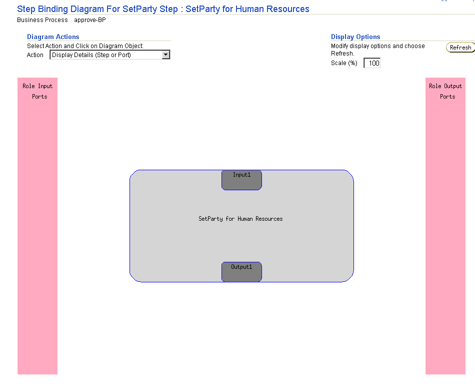
The Step Binding Diagram page displays the current state of a step, including its step ports, role ports, and data flows. In Figure 12-12, the SetParty step displays early after creation. A destination party has been set in the SetParty step (named Human Resources), but no events or data flows have been defined.
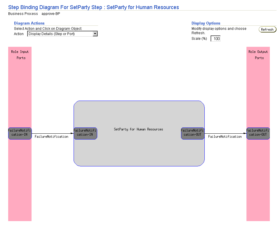
As you add additional steps, step ports, role ports, and role data flow to an integration, these changes are reflected in the Step Binding Diagram. For example, creating the FailureNotification-IN and FailureNotification-OUT step ports and role ports, and connecting these step ports to these role ports with role data flows causes the changes shown in Figure 12-13 to display in the Step Binding Diagram.
| Action | Description | See Also |
|---|---|---|
|
Display Details (Step or Port) |
Click the step, step port, or role port to display the details page for a step or port. |
|
|
Display Another Step Bindings Diagram |
Click to display the step binding diagram for the selected step |
This section |
|
Create Step Port |
Click the step or step port to display the page for creating a step port. If you click a role port, an error message appears. |
|
|
Update (Step or Port) |
Click the step, step port, or role port to display the page for updating a step, step port, or role port, respectively. |
|
|
Delete (Step or Port) |
Click the step, step port, or role port to display the page for deleting a step, step port, or role port, respectively. |
|
|
Create Data Flow |
Click the unbound step port or role port (such as a return code port) to display the page for creating a data flow to another port. If the port is already data flow-bound, an error message appears. If you click a step, the step details page displays all data ports for this step. You must choose the port for which to create a data flow. |
"Creating a Data Flow Between a Role Port and a Step Port" |
|
Delete Data Flow |
Click the step port or role port to display the details page for your selection. From this page, choose the data flow to delete. Click the step to display the details page for the step. From this page, choose the port, then choose the data flow to delete. |
When you click Apply or Cancel on an action page (create, update, or delete page) you are returned to the Step Binding Diagram. A confirmation or error message appears at the top of the diagram to indicate whether the apply action was successful or not. If successful, the diagram reflects the modification that was made.
The Oracle Application Server ProcessConnect user interface tool enables you to perform the business process management tasks shown in Figure 12-14 and Figure 12-15. These tasks are described in detail in this section. The business process is the center of the integration and implements the business logic and manages business events. The business process hides the unique characteristics of each party in an integration. The business process can contain all types of steps except translation steps. Ports in business processes can only be bound to business events. No port in a business process can be bound to a native event or application event.
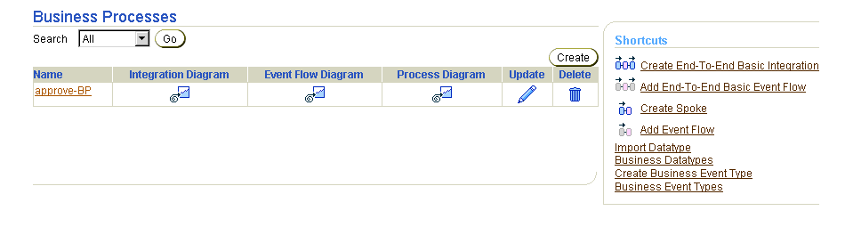
Selecting a business process in the Name column causes a details page such as that shown in Figure 12-15 to appear.
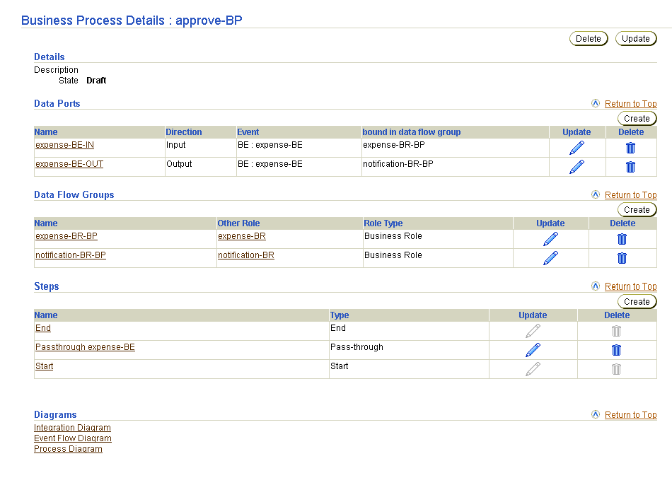
Table 12-3 identifies the business process management tasks shown in Figure 12-14 and Figure 12-15 and provides references to procedures for performing these tasks.
| Business Processes Page Elements | Management Task | First See Section... | Then See Section... |
|---|---|---|---|
|
Shortcuts section in Business Processes page of Figure 12-14 |
Take a shortcut to: |
N/A |
|
|
Create button in Business Processes page of Figure 12-14 |
Create a business process |
||
|
Delete column in Business Processes page of Figure 12-14 |
Delete a business process |
|
|
|
Update column in Business Processes page of Figure 12-14 |
Update a business process |
|
|
|
Name column in Business Processes page of Figure 12-14 (To access the details page shown in Figure 12-15) |
View details about a business process |
|
|
See Also:
"Business Process" for conceptual details about business processes |
Follow these instructions to access the business process management tasks shown in Figure 12-14 and Figure 12-15:
To access business process management tasks:
The Business Processes page appears. (See Figure 12-14.)
Follow these instructions to create a business process:
To create a business process:
The Create Business Process page appears.
approve-BP).
The business process is created and the Business Process Details : name page for the new business process appears. This page enables you to manage ports, data flows, and steps, and view diagrams of the business process. From the step page (accessible from the Business Process Details : name page), you can manage step ports, step data flows, and step control flows.
| Diagram | See Section... |
|---|---|
|
Integration Diagram |
|
|
Event Flow Diagram |
|
|
Process Diagram |
Follow these instructions to delete a business process:
To delete a business process:
The business process is deleted and the Business Processes page appears.
Follow these instructions to update a business process:
To update a business process:
The Update Business Process page appears.
The business process is updated and the Business Process Details : name page for the updated business process appears.
Follow these instructions to view details about a specific business process:
To view a business process:
The Business Process Details : name page appears for the selected business process.
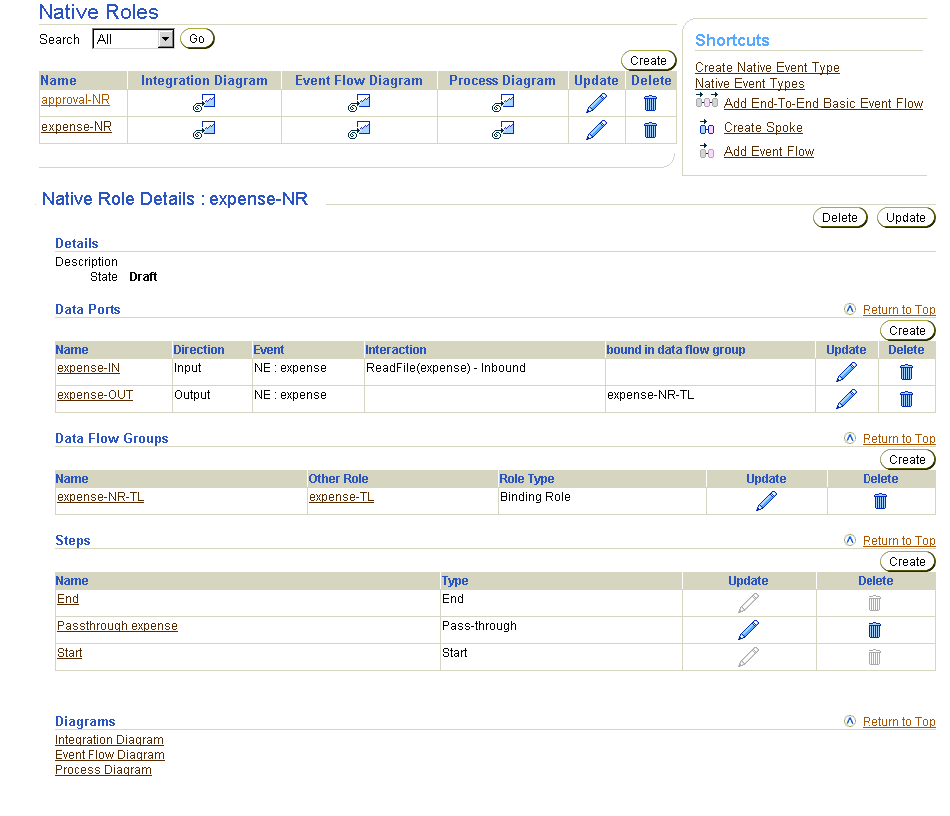
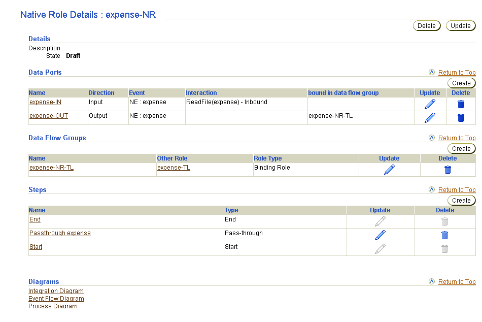
The Oracle Application Server ProcessConnect user interface tool enables you to perform the role management tasks shown in Figure 12-16. These tasks are described in detail in this section. Each task applies to all roles, regardless of the role type you are creating. Regardless of whether you are managing a native, application, business, translation binding, or transformation binding role, the same management pages appear. Only the page titles are different.
This section briefly describes each role type you can create:
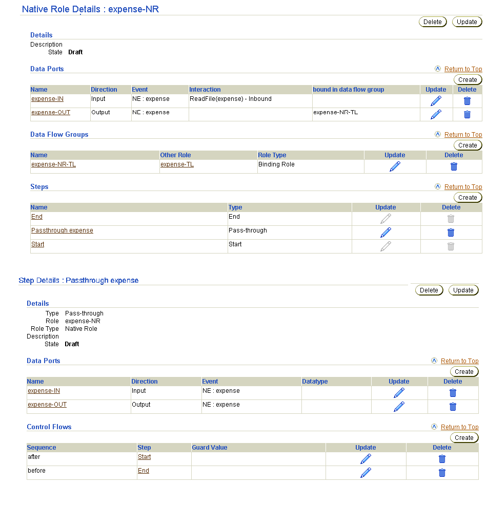
Native roles manage the interaction between native events. Pass-through steps and consume steps are typically used in native roles. Since the syntax of a native event is not known to Oracle Application Server ProcessConnect, transformations, conditions, and other steps cannot be performed. In most cases, the native event is passed through to the binding role for translation. Native roles can also be used to ignore native events that are not necessary for the integration (for example, acknowledgment events being sent as part of a protocol). In such cases, a consume step can be used in the native role to consume (prevent further processing from occurring) the event and not pass it onto the translation binding role.
Ports in native roles can only be bound to native events. No port in a native role can be bound to an application event or business event.
Translation binding roles operate as a bridge between native and application roles. This role translates the native event to an application event, and vice versa. This role can also consume native events and perform error processing for translations. For this reason, a translation binding role typically contains translation steps, consume steps, and conditions steps.
Additionally, a translation binding role can generate acknowledgments. In these cases, the translation binding role can contain transformation steps and split steps.
As with native events, application events are processed in a specific order. The order is determined by the construction of the application role. The application role usually contains pass-through steps and consume steps. Application roles can also generate acknowledgments instead of the translation binding role. Application role ports can only be bound to application events. No port in an application role can be bound to a native event or business event.
Transformation binding roles act as a bridge between business roles and application roles. This role transforms an application event to a business event, and vice versa. This role can also consume application events and perform the error processing for transformations. For this reason, a transformation binding role typically contains transformation steps, consume steps, split steps, and condition steps. A transformation binding role can also be used in event addressing (using event header rules) and in the creation of new events.
Transformation binding role ports that are bound to an application role through a data flow can only be connected to application events. Transformation binding role ports bound to a business role through a data flow can only be connected to business events.
As with native events and application events, business events must be processed in a predetermined order. A business role describes the processing of business events. The business role also isolates the business process from the rest of the processing and determines the branching of events (see data flow criteria). The business role typically contains pass-through steps and consume steps. This role can also contain transformation steps to generate new business events.
Business role ports can only be bound to business events. No port in a business role can be bound to a native event or application event.
Table 12-4 identifies the role management tasks shown in Figure 12-16 and provides references to procedures for performing these tasks.
| Roles Page Elements | Management Task | First See Section... | Then See Section... |
|---|---|---|---|
|
Shortcuts section in Native Roles page of Figure 12-16 |
Take a shortcut to: |
N/A |
|
|
Create button in Native Roles page of Figure 12-16 |
Create a role |
||
|
Delete column in Native Roles page of Figure 12-16 |
Delete a role |
|
|
|
Update column in Native Roles page of Figure 12-16 |
Update a role |
|
|
|
Name column in Native Roles page of Figure 12-16 (To access the details page shown in the lower page of Figure 12-16) |
View details about a role |
|
Follow these instructions to access the role management tasks shown in Figure 12-16:
To access role management tasks:
The Business Roles page appears by default.
Follow these instructions to create a role:
To create a role:
The Create type Role page appears.
where type is native, application, binding, or business.
expense-NR).
The role is created and the type Role Details : name page for the new role appears. This page enables you to manage ports, data flows, and steps, and view diagrams of the role. From the step page (accessible from the type Role Details : name page), you can manage step ports, step data flows, and step control flows.
| Diagram | See Section... |
|---|---|
|
Integration Diagram |
|
|
Event Flow Diagram |
|
|
Process Diagram |
Follow these instructions to delete a role:
To delete a role:
The role is deleted and the type Role page appears.
Follow these instructions to update a role:
To update a role:
The Update type Role page appears.
The role is updated and the type Role Details : name page for the updated role appears.
Follow these instructions to view details about a specific role:
To view a role:
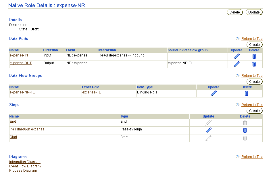
The type Role Details : name page appears for the selected role (in this example, a native role).
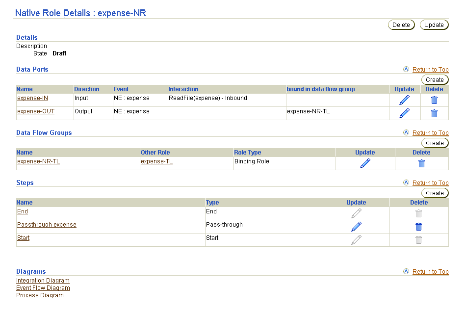
This page, as with the type Roles page shown in the upper figure of Figure 12-16, enables you to delete or update the selected role.
The Oracle Application Server ProcessConnect user interface tool enables you to perform the role port management tasks shown in Figure 12-17. These tasks are described in detail in this section. Role ports represent an input or output parameter of a role containing events. Role ports of roles are connected together by role data flow. This enables events to move from role to role.
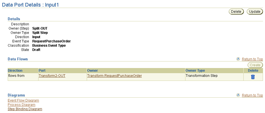
Selecting a role port in the Name column of the Data Ports section causes a details page such as that shown in Figure 12-18 to appear.
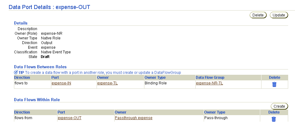
Table 12-5 identifies the role port management tasks shown in Figure 12-17 and Figure 12-18 and provides references to procedures for performing these tasks.
| Page Elements | Management Task | First See Section... | Then See Section... |
|---|---|---|---|
|
Create button in Data Ports section of Figure 12-17 |
Create a role port |
||
|
Delete column in Data Ports section of Figure 12-17 |
Delete a role port |
|
|
|
Update column in Data Ports section of Figure 12-17 |
Update a role port |
|
|
|
Name column in Data Ports section of Figure 12-17 (To access details page shown in Figure 12-18) |
View details about a role port |
|
|
|
Create button in Data Flows Within Role section of Figure 12-18 |
Create a data flow between a role port and a step port |
|
|
|
Delete column in Data Flows Within Role section of Figure 12-18 |
Delete a data flow between a role port and a step port |
|
|
See Also:
|
Follow these instructions to access the role port management tasks shown in Figure 12-17 and Figure 12-18:
To access role port management tasks:
| If You Select the... | This Page Appears... | Go To Step... |
|---|---|---|
|
Roles tab |
Business Roles page |
|
|
Business Processes tab |
Business Processes page |
The details page for the selected role or business process appears.
You can also manage some aspects of role ports from within a Process Diagram or Step Binding Diagram.
|
See Also:
"Viewing a Process Diagram" and "Viewing a Step Binding Diagram" for details on role port management capabilities |
Follow these instructions to create a role port:
To create a role port:
The Create Data Port on Role name page appears.
expense-OUT)
Pass-through steps send events to the next role without any processing. These steps are useful when no processing other than sending events is required. This option automatically creates two ports in the role:
If you do not select this box, you must manually create the second port and the step in between at a later time.
Your selection appears in the Name field.
The role port is created and the Data Port Details : name page for the new role port of the role appears.
Follow these instructions to delete a role port:
To delete a role port:
The role port is deleted and the type Role Details : name page appears.
Follow these instructions to update a role port:
To update a role port:
The Update Data Port on Role name page appears.
The role port is updated and the Data Port Details : name page for the updated role port appears.
Follow these instructions to view details about a specific role port:
To view a role port:
The Data Port Details : name page for the selected role port appears.
This page, as with the type Role Details : name page shown in Figure 12-17, enables you to delete or update the selected role port.
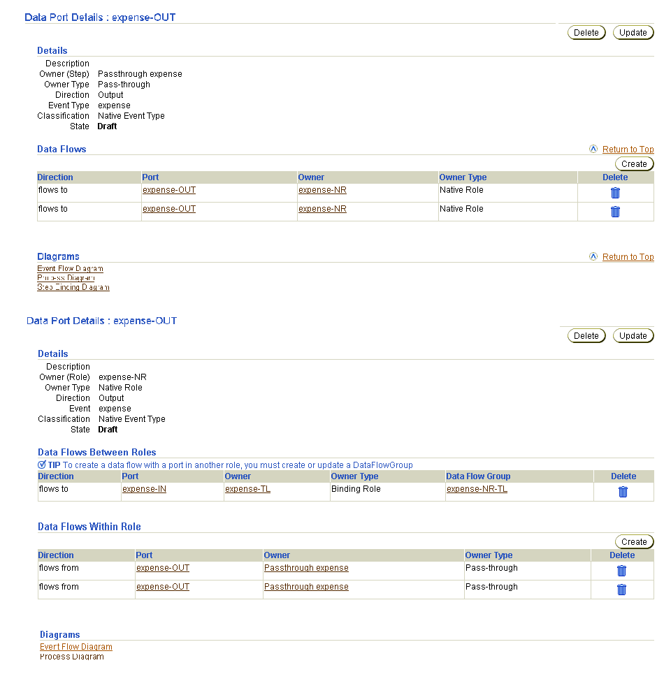
Follow these instructions to create a data flow between a role port and a step port:
To create a data flow between a role port and a step port:
The Data Port Details : name page appears. (See Figure 12-18.)
The Create Data Flow page appears with a list of compatible ports. Ports that are compatible for data flow have the following characteristics:
When a data flow is created between a port to which a datatype or event type is already assigned and a port to which no type is assigned, the port with no assigned type inherits the type of the assigned port (either datatype or event type).
The Data Port Details : name page appears. The data flow you created appears in the Data Flows Within Role section.
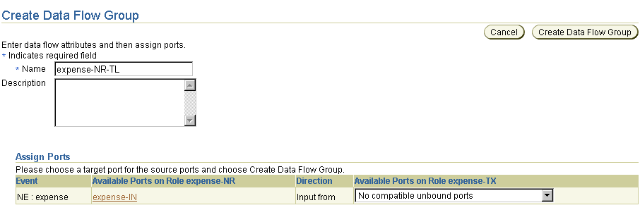
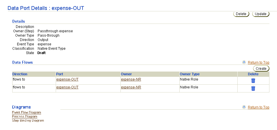
The Step Binding diagram displays the expense-OUT output role port connected through a data flow with the expense-OUT step port of a pass-through step.
Follow these instructions to delete a data flow between a role port and a step port:
To delete a role port a data flow between a role port and a step port:
The Data Port Details : name page appears.
The data flow is deleted and the Data Port Details : name page appears.
The Oracle Application Server ProcessConnect user interface tool enables you to perform the role data flow management tasks shown in Figure 12-19. These tasks are described in detail in this section. Role data flows connect the role ports of roles together, which enable events to move from role to role.
A data flow group is a collection of role data flows between any two given roles. During runtime, data flow groups route events when a role can be connected to more than one role. Data flow criteria is used by the runtime to choose the data flow to use when the same port is the source for more than one data flow.
For example, a company's purchasing system is connected to two trading partners (for this example, TP1 and TP2). If both trading partners use the same business-to-business (B2B) protocol, purchase order processing is the same and the same set of roles is used. A third trading partner is then added that uses a different protocol. For the third trading partner, a different transformation, translation, and set of roles are required. In this case, purchase order processing is the same until transformation is performed. The business role outbound port is connected to a port of a transformation binding role (named TBR1, for example). When a third partner is added (for this example, TP3), the same outbound port of the business role must be connected to a port of a different transformation binding role (named TBR2, for example) containing the new transformation.
Data flow criteria enables you to achieve this requirement. For example, there are two data flow groups:
During design, you specify the conditions during which to use DFG1 and during which to use DFG2. These conditions are specified by setting a data flow criteria for the data flow group. In this scenario, DFG2 is used by the third trading partner (TP3) only.
DFG1 is used by trading partners TP1 and TP2. The data flow criteria for DFG2 is set to the third trading partner. There is no criteria required for DFG1, as this is the default.
If an additional branch is required, the same procedure is followed. When more than one data flow group is associated with a criteria, the priority is also specified. Oracle Application Server ProcessConnect then executes the criteria in the same order for every integration. Oracle Application Server ProcessConnect currently supports only simple party-based criteria.
Table 12-6 identifies the role port management tasks shown in Figure 12-19 and provides references to procedures for performing these tasks.
| Page Elements | Management Task | First See Section... | Then See Section... |
|---|---|---|---|
|
Create button in Data Flow Groups section of Figure 12-19 |
Create a role data flow group |
||
|
Delete column in Data Flow Groups section of Figure 12-19 |
Delete a role data flow |
|
|
|
Update column in Data Flow Groups section of Figure 12-19 |
Update a role data flow |
|
|
|
Other Role column in Data Flow Groups section of Figure 12-19 |
View the other role to which the role data flow is connected |
|
|
|
Name column in Data Flow Groups section of Figure 12-19 |
View details about a role data flow |
|
|
See Also:
|
Follow these instructions to access the role data flow management tasks shown in Figure 12-19:
To access role data flow management tasks:
| If You Select the... | This Page Appears... | Go To Step... |
|---|---|---|
|
Roles tab |
Business Roles page |
|
|
Business Processes tab |
Business Processes page |
The details page for the selected role or business process appears.
A data flow group is a collection of all the data flows between two roles. Two roles are bound both by a data flow group (as seen in the Integration Diagram) and by one or more data flows (as seen in the Event Flow Diagram).
Two roles have only a single data flow group between them. You use the Create Data Flow Group page described in this section to create a data flow group and one or more data flows. If you need to add more data flows after the data flow group is created, use the Update Data Flow Group page described in "Updating a Role Data Flow". Data flows within a role (that is, role to step and step to step data flows) are not grouped into data flow groups. These data flows belong to the role itself.
If you are creating a data flow group between a business role and a transformation binding role, you can also optionally provide a data flow criteria for this group. This feature enables the business role to be data flow-bound more than once to different transformation binding roles (in different data flow groups with different data flow criteria for each). A data flow criteria is defined by specifying a party (application or trading partner) and a priority value that determines the order of execution. For example, your organization may be conducting business with two parties. One party has slightly different transformation requirements than the other party. You can create one data flow group from the business role that branches to one transformation binding role for one party, and another data flow group that branches to another transformation binding role for the other party. You specify a priority value for the data flow group of the party that you want to execute first. For the other party, known as the default data flow group, you do not specify a priority value. The Integration Diagram shows this role branching and displays the criteria for each branch.
You can set the party before (the typical method) or during design time for data flow criteria. If you know the party at design time, use the SetParty step and explicitly route an event to an outbound spoke. If the party is not known at design time, use the transformation step in the transformation binding role of the inbound spoke to set the party into the event header, and then use the data flow criteria on the data flow group between the outbound business role and (multiple) outbound transformation binding roles to choose the correct spoke by party.
Follow these instructions to create a role data flow group and one or more data flows, and also to optionally create a data flow criteria between a business role and a transformation binding role.
To create a role data flow group:
The first Create Data Flow Group page appears.
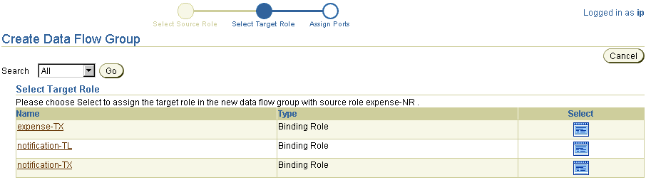
This page enables you to select the target role to connect with a data flow group to the source role selected in Step 4 (for this example, native role approval-NR). After complete, the data flow group connects the role port of this role (the source role) and the role port of another role (the target role).
The second Create Data Flow Group page appears. The fields that display are based on the type of roles for which you are creating a data flow group.
1 ensures that this data flow group is executed first. Note that you must leave the Priority field blank for at least one data flow group. For example, if you are creating three data flow groups, leave the Priority field blank for one of the data flow groups; this becomes the default data flow group.
When a data flow is created between a port to which a datatype or event type is already assigned and a port to which no type is assigned, the port with no assigned type inherits the type of the assigned port (either datatype or event type).
| Selection | Description |
|---|---|
|
No compatible unbound ports |
Displays when the selected target role has no ports that match the rules described in Step 6. |
|
Create new role port |
Creates a new port on the target role and creates the data flow to it. The created port is compatible in that it has the same event type as the source port and is of the opposite direction. |
|
Create new role ports with pass-through step |
The same as Create new role port, plus it creates the pass-through step, the step ports, the role port on the other side, and the data flow groups between the step and role ports. |
This creates a data flow group between the role port of the source role and the role port of the target role. The Data Flow Group Details : name page for the created data flow appears.
Follow these instructions to delete a role data flow:
To delete a role data flow:
The role data flow is deleted and the type Role Details : name page appears.
You can update role data flow from this page by adding new data flows or deleting data flows by deselecting them. Follow these instructions to update a role data flow:
To update a role data flow:
The Update Data Flow Group page appears.
The role data flow is updated and the Data Flow Group Details : name page for the updated role data flow appears.
Follow these instructions to view details about the other role (the target role) connected to the role data flow:
To view the other role connected to the role data flow:
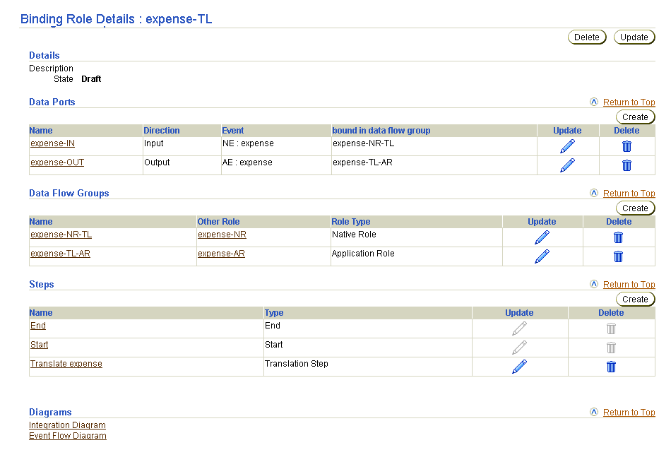
The type Role Details : name page appears (for example, if the other role was a binding role):
Follow these instructions to view details about a specific role data flow:
To view a role data flow:
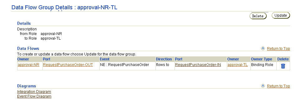
The Data Flow Group Details : name page for the selected role data flow appears.
The Oracle Application Server ProcessConnect user interface tool enables you to perform the step management tasks shown in Figure 12-20. These tasks are described in detail in this section.
Each role and business process consists of a set of steps. A step defines execution logic that is applied to one or more events or control flows and data flows in a role. There are two types of steps:
Some of these steps have ports that represent the input and output parameters. Steps with ports can have data flows associated with these ports. In addition, steps can have incoming and outgoing control flows.
This section provides details about each step type that you can create and design:
This step is a pseudo-step that indicates the start of a role. It is automatically created when a new role is created.
This step has no IN ports and no OUT ports.
There can be any number of outgoing control flows from this step. This step can have no incoming control flows or data flows.
This step must exist in every role in the integration.
This step is executed after the role has an event on its initiating IN port.
This step indicates completion of role processing. This step is automatically created when a new role is created.
This step has no IN ports and no OUT ports.
There can be any number of incoming control flows coming into this step. This step cannot have any outgoing control flows or data flows.
This step must exist in every role in the integration.
This step is executed after all incoming control flows have been executed. After execution of this step, the role processing is complete and the role instance is marked as WorkflowComplete. If all events on the outbound ports of the role have been picked up as well, then the role instance is Complete.
This step passes through the event or datatype on its IN port to its OUT port. The event contents are not altered.
|
See Also:
"Error Handling with Step Return Code Ports" for an example of a role that uses a pass-through step |
This step has exactly one IN port and one OUT port. These ports can be associated with an event type or a datatype. Both the IN port and the OUT port must be associated with the same event type or datatype.
This step can have one incoming data flow and one outgoing data flow. There can be any number of incoming control flows and outgoing control flows.
This step is typically used in the native role, application role, or business role if there is no party-specific event processing required. This step can be used in other roles, if required.
This step is executed after all incoming control flows and data flows have executed. The event or datatype moves to the OUT port if the step successfully executes.
This step transforms a set of events or datatypes into another set of events or datatypes. This step is associated with a transformation map. The transformation map parameters must correspond to the types on the IN ports and OUT ports. The events or datatypes to be transformed are on the IN ports. The new events or datatypes created after transformation are put on the OUT ports.
|
See Also:
"Error Handling with Step Return Code Ports" for an example of a role that uses a transformation step |
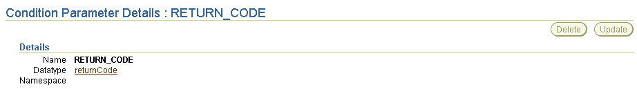
This step can have multiple IN ports and multiple OUT ports. These ports can be associated with an event type or a datatype (based on the return values from the transformation map). This step also has a return code port that is associated with the returnCode datatype.
This step can have any number of incoming control flows and outgoing control flows. Each IN port must have an incoming data flow. Each OUT port must have an outgoing data flow. Data flow from the return code port is optional.
This step can only operate on application datatypes or event types, or business datatypes or event types. This step is ideally used only in the transformation binding role, but it can be used in all roles except the native role.
This step is executed after all incoming control flows and data flows have executed. The transformation map is invoked when there is data on all the IN ports. After the transformation step has executed, the return code port is populated with a datatype that indicates success or failure. If transformation is successful, the OUT ports and return code port are populated. If there is a failure, the OUT ports are not filled; only the return code port is populated with a datatype containing the error code and error message. The events or datatypes on the IN port are marked as consumed.
This step translates a native event type or datatype to an application event type or datatype, and vice versa. The IN port must be associated with the event or datatype to be translated. The OUT port must be associated with the translated event or datatype. The translation step converts the syntax from the native format to the interpretable application format, or vice versa.
The new event or datatype created after translation is put on the OUT ports.
|
See Also:
"Application Events and Translation" for additional details about translation |
This step has one IN port and two OUT ports. There is one OUT port for the translated event or datatype and one for the return code port (which is associated with the returnCode datatype).
The IN and OUT ports can be associated with native or application event types or datatypes. If the IN port is associated with a native event type, the OUT port must be associated with the application event, and vice versa. You cannot have a datatype associated with the IN port and an event type associated with the OUT port. Both ports must be associated with either datatypes or event types.
This step can have one incoming data flow and one outgoing data flow. There can be any number of incoming control flows and outgoing control flows. Data flow from the return code port is optional.
This step is typically used in the translation binding role.
This step is executed after all incoming control flows and data flows have executed. The translation is done when there is a data or event instance on the IN port. After the translation step has executed, the return code port is populated with a datatype that indicates success or failure. If translation is successful, both the OUT port and return code port are populated. If there is a failure, the OUT port is not filled, only the return code port is populated with a datatype containing the error code and error message. The event on the IN port is consumed.
This step evaluates a specific condition on an event type or datatype. This step is associated with a condition expression. The datatype for the IN port is automatically selected based on the datatype or event type used by the condition expression. After the condition expression is evaluated, one of the outgoing control flows (either true or false) is executed.
|
See Also:
|
This step has one IN port and one OUT port (other than the return code port). This OUT port is a return code port associated with the returnCode datatype. The IN port can be associated with an application or business event or datatype. This is automatically selected based on the condition expression used for the step.
This step must have one incoming data flow. There can be any number of incoming control flows and exactly two outgoing control flows: one for true guard value and one for false guard value. Data flow from the return code port is optional.
This step can only operate on application datatypes or event types, or business datatypes or event types. This step is ideally used only in the transformation binding role, but can be used in all roles except the native role.
This step is executed after all incoming control flows and data flows have executed. The condition expression is evaluated when there is a data or event instance on the IN port. After the condition step has executed, the return code port is populated with a datatype that indicates success or failure. If expression evaluation is complete, based on the result (true or false), one of the outgoing control flows is executed. If there is a failure when evaluating the condition expression, the outgoing control flow is not executed and the return code port is populated with a datatype containing the error code and error message.
This step sets a specific destination party (application or trading partner) for an event type or datatype.
|
See Also:
"Selecting the Destination Party in the SetParty Step" for an example of a role that uses a SetParty step |
This step has exactly one IN port and one OUT port. These ports can be associated with an event type or a datatype. Both the IN port and the OUT port are associated with the same event type or datatype.
This step can have one incoming data flow and one outgoing data flow. There can be any number of incoming control flows and outgoing control flows.
This step is typically used in the business role or business process.
This step is executed after all incoming control flows and when there is data on the IN port. The event type or datatype header is updated with the destination party and then moved to the OUT port.
This step consumes and prevents further processing of an event or datatype. The IN port must be associated with the event or datatype to be consumed. This step is typically used to consume acknowledgments.
|
See Also:
"Acknowledgment Consumption and Generation" for an example of a role that uses a consume step |
This step has one IN port and no OUT ports.
This step must have one incoming data flow. There are no outgoing data flows from this step. There can be any number of incoming control flows and outgoing control flows.
This step can operate on any type of event or datatype, and can be used in any role.
This step is executed after all incoming control flows have executed and when there is data on the IN port. The incoming event is marked as consumed and further processing is disabled.
This step makes multiple copies of an event. The event on the IN port is copied and the new events are placed on each of the OUT ports.
|
See Also:
"Error Handling with Step Return Code Ports" for an example of a role that uses a split step |
This step has one IN port and multiple OUT ports. The IN port can be associated with an event or datatype.
Each IN port must have an incoming data flow. Each OUT port must have an outgoing data flow. There can be any number of incoming control flows and outgoing control flows.
This step can operate on any type of event or datatype, and can be used in any role.
This step is executed after all incoming control flows have executed and when there is data on the IN port. The incoming event is marked as consumed and copies of the event are placed on the OUT ports.
This step waits for at least one incoming control flow. The step is executed as soon as one of the incoming control flows is executed.
This step has no IN ports or OUT ports.
This step can have any number of incoming control flows and outgoing control flows. This step does not have any data flows.
This step can be used in any role.
This step is executed after any incoming control flow has executed. In all other steps, the steps are executed only when all the incoming control flows have executed. This is the only case where the step is executed after any one of the incoming control flows. Ensure that the incoming control flows are coming from mutually exclusive paths. Otherwise, the role processing is not deterministic.
|
See Also:
"Designing Roles to Ensure Proper Validation" for examples of roles that use Or steps. |
This step waits for all incoming control flows, and executes after all incoming control flows have executed. This step is not typically required since all steps (except an Or step), implicitly provide AND step behavior for the incoming control flows.
This step has no IN ports or OUT ports.
This step can have any number of incoming control flows and outgoing control flows. This step does not have any data flows.
This step can be used in any role.
This step is executed after all of the incoming control flows have executed. Ensure that the incoming control flows are not coming from mutually exclusive paths. Otherwise, this step may never execute and role processing may halt here.
Table 12-7 identifies the step management tasks shown in Figure 12-20 and provides references to procedures for performing these tasks.
| Page Elements | Management Task | First See Section... | Then See Section... |
|---|---|---|---|
|
Create button in Steps section of Figure 12-20 |
Create a step |
||
|
Delete column in Steps section of Figure 12-20 |
Delete a step |
|
|
|
Update column in Steps section of Figure 12-20 |
Update a step |
|
|
|
Name column in Steps section of Figure 12-20 |
View details about a step |
|
|
See Also:
|
Follow these instructions to access the step management tasks shown in Figure 12-20:
To access step management tasks:
| If You Select the... | This Page Appears... | Go To Step... |
|---|---|---|
|
Roles tab |
Business Roles page |
|
|
Business Processes tab |
Business Processes page |
The details page for the selected role or business process appears.
You can also manage steps from within a Process Diagram or Step Binding Diagram.
|
See Also:
"Viewing a Process Diagram" and "Viewing a Step Binding Diagram" for details on step management |
Follow these instructions to create a step:
To create a step:
The Create Step in Role name page appears.
Passthrough_expense).
The page refreshes based on the step type selected in Step 5.
For most steps that have both an input and output port, the ports must have the same event type or datatype. For example, a SetParty step or pass-through step have input and output ports of the same event or datatype. The only exceptions to this are the transformation and translation steps, which can convert the event or datatype between the in and out ports.
| If You Select... | Then... |
|---|---|
|
Condition step |
Select the condition expression to use from the Condition Expression list. A port is created for each parameter in the condition expression. This is the condition expression you created in "Managing Condition Expressions in Steps". |
|
SetParty Step |
Select the destination party (trading partner or application) to use from the Party list. See Also: "Creating an Application" and "Creating a Remote Trading Partner" (The host trading partner automatically displays for selection in the Party list.) |
|
Transformation Step |
Select the datatype transformation map (for example, copy:from=string->to=string) to use from the Transformation Map list. A port is created for each parameter in the transformation map. See Also: "Managing Transformation Statements" |
| Field | Description |
|---|---|
|
Sequence after Step |
Select a step. The step you select is executed before the step you selected in Step 5. |
|
Sequence before Step |
Select a step. The step you select is executed after the step you selected in Step 5. |
|
Note: This field only displays for a condition step. |
A guard value is only required for a condition step for the before section of the Sequence list. This means that the value only has meaning on a control flow that is going out of a condition step.
After control flow creation, the guard value displays in the Guard Value column of the Control Flows section, as shown in Figure 12-23. |
The step is created and the Step Details : name page appears. Step type-specific metadata also appears in the Details section of the Step Details : name page. (See the page in "Viewing a Step" for an example.) Some step types include links to other pages. For example, the transformation step includes a link to the Transformation Map Details page for the transformation map selected in Step 7.
Based on the type of step created, various input ports (named Input1), output ports (named Output1 and Output2), or return code ports are also automatically created. These ports have no event type or datatype assigned to them. The ports must have an assigned type before they can be included in a deployed configuration. A port with no assigned type often inherits the type of a port to which it is data flow-bound (either datatype or event type) or the type of another port in the same step.
The following table lists the ports automatically created.
| For This Step... | Input1 Port Created? | Output1 Port Created? | Output2 Port Created? | Return Code Port Created? |
|---|---|---|---|---|
|
AndFoot 1 |
No |
No |
No |
No |
|
Condition |
Yes |
No |
No |
Yes |
|
Consume |
Yes |
No |
No |
No |
|
Or1 |
No |
No |
No |
No |
|
Pass-through |
Yes |
Yes |
No |
No |
|
SetParty |
Yes |
Yes |
No |
No |
|
Split |
Yes |
Yes |
Yes |
No |
|
Translation |
Yes |
Yes |
No |
Yes |
|
Transformation |
Yes |
Yes |
No |
Yes |
|
1
No ports are created; only control flows, which do not use ports, are used with this step type. |
"Creating a Step Port" to create additional step ports
See Also:
Follow these instructions to delete a step:
To delete a step:
The step is deleted and the type Role Details : name page appears.
You can update step-specific details. For example, for a SetParty step, you can change the party with which the step is associated by selecting a different party from the list. For a transformation step, if you chose a different transformation map, a new set of ports are created that correspond to the new map parameters. The data flows of the old ports are reconnected to the new ports if the event type or datatype of the ports match. The old ports are then deleted. The same situation also applies for condition steps and conditional expressions.
Follow these instructions to update a step:
To update a step:
The Update Step in Role name page appears.
The step is updated and the Step Details : name page appears.
Follow these instructions to view details about a specific step:
To view a step:
The Step Details : name page appears.
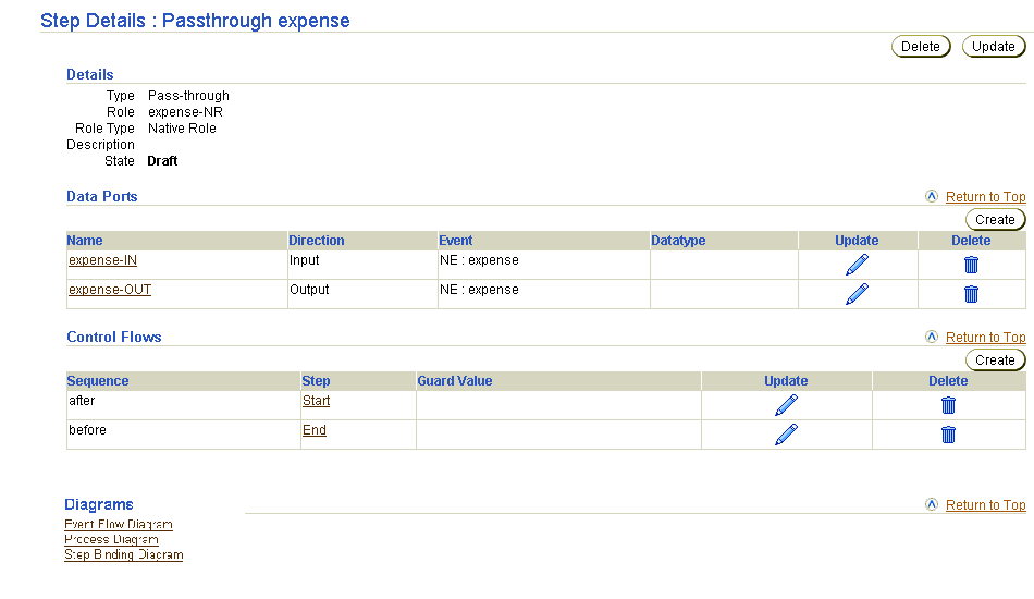
This page enables you to view details about a step. The Data Ports section of this page lists the data ports for the role. This page, as with the type Role Details : name page shown in Figure 12-20, enables you to delete or update the selected step.
The Oracle Application Server ProcessConnect user interface tool enables you to perform the step port management tasks shown in Figure 12-21. These tasks are described in detail in this section. Step ports are the input and output parameters of steps in roles. Step ports work with data flows and control flows to connect steps in roles together. Step ports also work with data flows to connect incoming role ports to incoming step ports and outgoing step ports to outgoing role ports.
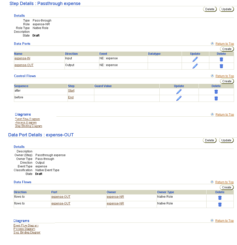
Table 12-8 identifies the step port management tasks shown in Figure 12-21 and provides references to procedures for performing these tasks.
| Step Details Page Elements | Management Task | First See Section... | Then See Section... |
|---|---|---|---|
|
Create button in Data Ports section of Figure 12-21 |
Create a step port |
||
|
Delete column in Data Ports section of Figure 12-21 |
Delete a step port |
|
|
|
Update column in Data Ports section of Figure 12-21 |
Update a step port |
|
|
|
Name column in Data Ports section of Figure 12-21 (To access the details page in the lower page of Figure 12-21) |
View details about a step port |
|
|
See Also:
|
Follow these instructions to access the step port management tasks shown in Figure 12-21:
To access step port management tasks:
| If You Select the... | This Page Appears... | Go To Step... |
|---|---|---|
|
Roles tab |
Business Roles page |
|
|
Business Processes tab |
Business Processes page |
The details page for the selected role or business process appears.
The Step Details : name page appears.
You can also manage some aspects of step ports from within a Process Diagram or Step Binding Diagram.
|
See Also:
"Viewing a Process Diagram" and "Viewing a Step Binding Diagram" for details on step port management capabilities |
Several default step ports are automatically created when you create a step. You can also create additional step ports, as needed. Follow these instructions to create a step port:
To create a step port:
The Create Data Port on Step Details : name page appears.
expense-OUT).
The page refreshes to display additional fields.
Your selection appears in the Name field.
Your selection appears in the Name field.
The step port is created, and you are returned to the Step Details : name page.
Follow these instructions to delete a step port:
To delete a step port:
You are returned to the Step Details : name page.
Follow these instructions to update a step port:
To update a step port:
The Update Data Port on Step name page appears.
The step port is updated and the Data Port Details : name page appears.
Follow these instructions to view details about a specific step port:
To view a step port:
The Data Port Details : name page appears.
This page enables you to view details about a step port. This page, as with the Step Details : name page shown in the upper page of Figure 12-21, enables you to delete or update the selected step port.
The Oracle Application Server ProcessConnect user interface tool enables you to perform the step data flow management tasks shown in Figure 12-22. These tasks are described in detail in this section. Step data flows connect the ports of steps together, which enable events to move through steps.
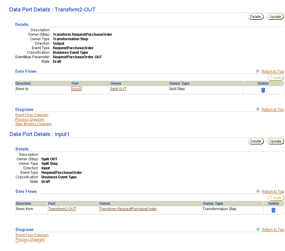
Table 12-9 identifies the step data flow management tasks shown in Figure 12-22 and provides references to procedures for performing these tasks.
| Page Elements | Management Task | First See Section... | Then See Section... |
|---|---|---|---|
|
Create button in upper page of Figure 12-22 |
Create a step data flow |
||
|
Delete column in upper page of Figure 12-22 |
Delete a step data flow |
|
|
|
Port column in upper page of Figure 12-22 (To access the details page in the lower page of Figure 12-22) |
View the target port for the step data flow |
|
|
See Also:
|
Follow these instructions to access the step data flow management tasks shown in Figure 12-22:
To access step data flow management tasks:
| If You Select the... | This Page Appears... | Go To Step... |
|---|---|---|
|
Roles tab |
Business Roles page |
|
|
Business Processes tab |
Business Processes page |
The details page for the selected role or business process appears.
The Step Details : name page for the selected step appears. (See the upper page of Figure 12-21.)
The Data Port Details : name page for the selected data port appears. (See the upper page of Figure 12-22.)
You can also manage some aspects of step data flows from within a Process Diagram or Step Binding Diagram.
|
See Also:
"Viewing a Process Diagram" and "Viewing a Step Binding Diagram" for details on step data flow management capabilities |
You can create step data flows for all steps with the exception of an And step and an Or step. Follow these instructions to create a step data flow:
To create a step data flow:
The Create Data Flow page appears.
A step port can be data flow-bound to either a role port or another step port. For a role port, the direction of the ports is the same. For example, an input step port is bound to an input role port, whereas an input step port is bound to an output step port.
When a data flow is created between a port to which a datatype or event type is already assigned and a port to which no type is assigned, the port with no assigned type inherits the type of the assigned port (either datatype or event type).
The step data flow is created and the Data Port Details : name page appears.
Follow these instructions to delete a step data flow:
To delete a step data flow:
You are returned to the Data Port Details : name page.
Follow these instructions to view details about the target port of a step data flow:
To view the target port of a step data flow:
The Data Port Details : name page appears.
This page enables you to view details about the target port of a step data flow. In this example, the target port is part of a step.
The Oracle Application Server ProcessConnect user interface tool enables you to perform the step control flow management tasks shown in Figure 12-23. These tasks are described in detail in this section. Control flows between steps indicate the execution order of steps. You can also create step control flows when you create a step.
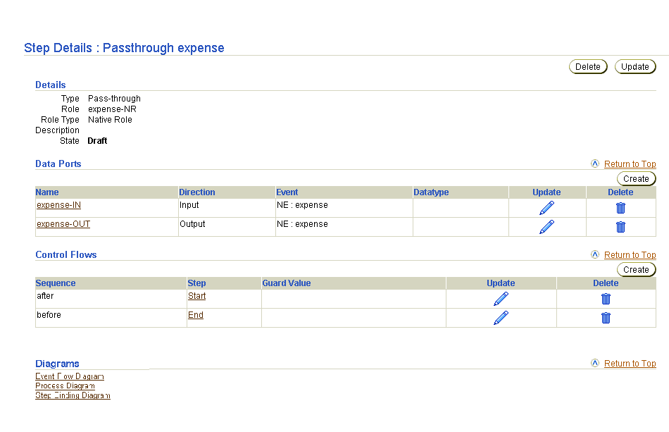
Table 12-10 identifies the step control flow management tasks shown in Figure 12-23 and provides references to procedures for performing these tasks.
| Step Details Page Elements | Management Task | First See Section... | Then See Section... |
|---|---|---|---|
|
Create button in Control Flows section of Figure 12-23 |
Create a step control flow |
||
|
Delete column in Control Flows section of Figure 12-23 |
Delete a step control flow |
|
|
|
Update column in Control Flows section of Figure 12-23 |
Update a step control flow |
|
|
See Also:
|
Follow these instructions to access the step control flow management tasks shown in Figure 12-23:
To access step control flow management tasks:
| If You Select the... | This Page Appears... | Go To Step... |
|---|---|---|
|
Roles tab |
Business Roles page |
|
|
Business Processes tab |
Business Processes page |
The details page for the selected role or business process appears.
The Step Details : name page for the selected step appears. (See Figure 12-23.)
You can also manage control flow from within a Process Diagram.
Follow these instructions to create a step control flow:
To create a step control flow:
The Create Control Flow for Step name page appears.
| Field | Description |
|---|---|
|
Sequence * |
Select the order in which to perform this step (either after or before). |
|
Step * |
Select the step to perform in sequence with the step you are creating. |
|
Note: This field only displays if you are creating a step control flow for a condition step. |
A guard value is only required for a condition step if before is selected from the Sequence list. This means that the value only has meaning on a control flow that is going out of a condition step.
After control flow creation, the guard value displays in the Guard Value column of the Control Flows section in Figure 12-23. |
The step control flow is created and the Step Details : name page appears.
Follow these instructions to delete a step control flow:
To delete a step control flow:
The step control flow is deleted and the Step Details : name page appears.
Follow these instructions to update a step control flow:
To update a step control flow:
The Update Control Flow on Step name page appears.
The step control flow is updated and the Step Details : name page appears.
The Oracle Application Server ProcessConnect user interface tool enables you to perform the condition expression management tasks shown in Figure 12-24. These tasks are described in detail in this section. Condition expressions enable you to define that a specific action be performed in a condition step based on the result of an expression. For example, you can specify that a specific condition be performed if the price field of a purchase order is over a specific number, such as notifying a second approver before the purchase order can be approved.
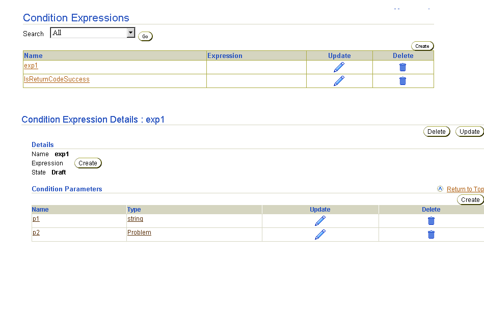
Table 12-11 identifies the condition expression management tasks shown in Figure 12-24 and provides references to procedures for performing these tasks.
| Page Elements | Management Task | First See Section... | Then See Section... |
|---|---|---|---|
|
Create button in Condition Expressions page of Figure 12-24 |
Create a condition expression |
||
|
Delete column in Condition Expressions page of Figure 12-24 |
Delete a condition expression |
|
|
|
Update column in Condition Expressions page of Figure 12-24 |
Update a condition expression |
|
|
|
Name column in Condition Expressions page of Figure 12-24 (To access the details page in the lower page of Figure 12-24) |
View details about a condition expression |
|
|
|
Create button in Condition Parameters section of Condition Expression Details page of Figure 12-24 |
Create a condition parameter |
|
|
|
Delete column in Condition Expression Details page of Figure 12-24 |
Delete a condition parameter |
|
|
|
Update column in Condition Expression Details page of Figure 12-24 |
Update a condition parameter |
|
|
|
Create button in Details section in Condition Expression Details page of Figure 12-24 |
Build a condition expression |
|
|
|
Name column in Condition Expression Details page of Figure 12-24 |
View a condition parameter |
|
|
See Also:
The following sections for viewing datatype and event type details that are accessible from the Type column of the Condition Parameters section in the lower page of Figure 12-24: |
Follow these instructions to access the condition expression management tasks shown in Figure 12-24:
To access condition expression management tasks:
The Condition Expressions page appears. (See the upper page of Figure 12-24.)
Follow these instructions to create a condition expression:
To create a condition expression:
The Create Condition Expression page appears.
The condition expression is created and the Condition Expression Details page for the created condition expression appears.
|
See Also:
"Creating a Condition Parameter" to add condition parameters to the condition expression |
Follow these instructions to delete a condition expression:
To delete a condition expression:
The condition expression is deleted and the Condition Expressions page appears.
Follow these instructions to update a condition expression:
To update a condition expression:
The Update Condition Expression page appears.
The condition expression is updated and the Condition Expression Details page for the updated condition expression appears.
Follow these instructions to view details about a specific condition expression:
To view a condition expression:
The Condition Expression Details page for the selected condition expression appears.
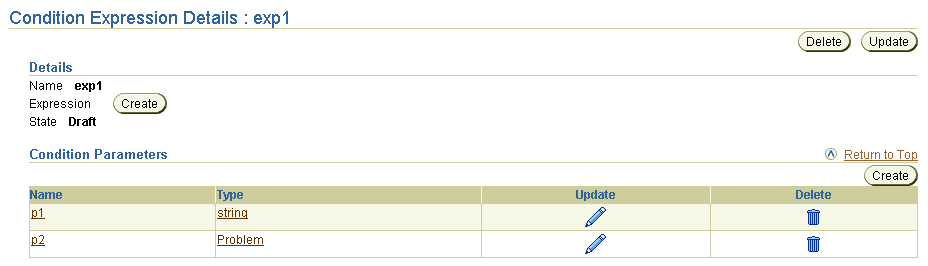
Text description of the illustration details_cond_express.gif
This page, as with the Condition Expressions page shown in the upper page of Figure 12-24, enables you to delete or update the selected condition expression.
Follow these instructions to create a condition parameter for a condition expression:
To create a condition parameter:
The Condition Expression Details page for the selected condition expression appears.
The Create Condition Parameter page appears.
The page refreshes to display additional fields.
The condition parameter is created and the Condition Parameter details page for the created condition parameter appears.
"Building a Condition Expression" to build a condition expression of condition parameters
See Also:
Follow these instructions to delete a condition parameter:
To delete a condition parameter:
The Condition Expression Details page for the selected condition expression appears.
The condition parameter is deleted and the Condition Parameter Details page appears.
Follow these instructions to update a condition parameter:
To update a condition parameter:
The Condition Expression Details page for the selected condition expression appears.
The Update Condition Parameter page appears.
The condition parameter is updated and the Condition Parameter Details page for the updated condition parameter appears.
Follow these instructions to build a condition expression. This expression uses the condition parameters created in "Creating a Condition Parameter".
To build a condition expression:
The Condition Expression Details page for the selected condition expression appears.
The Create Condition page appears.
The Create Expression page appears.
Text description of the illustration create_cond_express.gif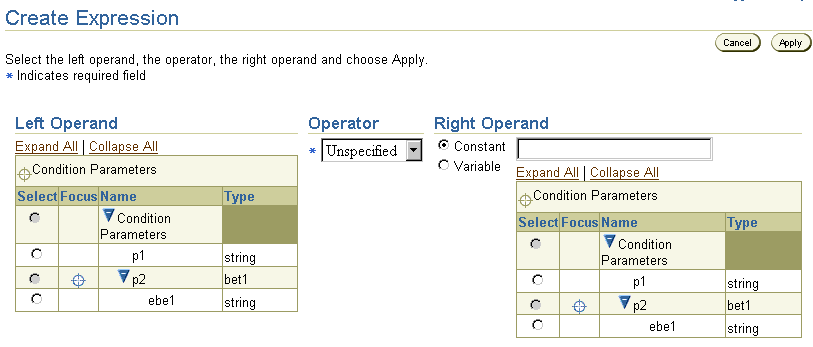
The condition expression is built.
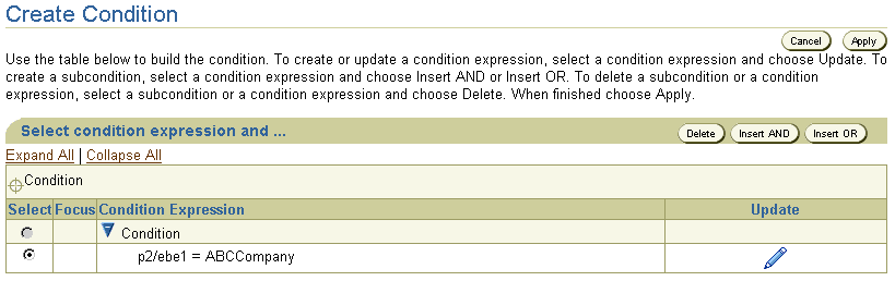
Text description of the illustration details_condition_expression.gif
You can now select this condition expression when creating a condition step type in a role on the Create Step in Role name page:
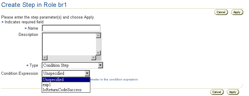
Text description of the illustration create_condition_step.gif
|
See Also:
"Creating a Step" for instructions on creating a condition step type and selecting a condition expression (for this example, condition expression exp1 appears) |
Follow these instructions to view a condition parameter:
To view a condition parameter:
The Condition Expression Details page for the selected condition expression appears.
The Condition Parameter Details page appears.
This page, as with the Condition Expression Details page shown in the lower page of Figure 12-24, enables you to delete or update the selected condition parameter.
This section provides examples of valid and invalid step, port, data flow, and control flow designs. Methods for avoiding these design problems are also described.
This section contains these topics:
A loop is a series of steps connected either through data flows or control flows in which the last step connects back to the first step. Loops can be inside a single role or can span multiple roles. Do not create loops when designing steps in roles even though the Oracle Application Server ProcessConnect user interface tool does not prevent you from this activity. If you create loops, integration validation fails when you attempt to create a configuration to deploy.
Figure 12-25 shows a loop within a single transformation binding role. The highlighted data flow and control flow between Transformation 1 and Transformation 2 of Figure 12-25 identifies the invalid loop.
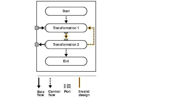
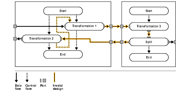
Figure 12-26 shows a loop that spans a transformation binding role and a business role. The highlighted data flow and control flow between Transformation 1, Transformation 3, Split, and Transformation 2 identifies the invalid loop.
To ensure valid use of Or steps, only design mutually-exclusive control flows going into an Or step. Mutually-exclusive flows are a set of paths, with only one path possible at runtime. Valid Or steps prevent race conditions from occurring at runtime, which prevent nondeterminicity in the system.
To ensure valid use of And steps, only design nonmutually-exclusive data flows or control flows going into an And step. Nonmutually-exclusive control flows are paths that can be taken simultaneously at runtime. Valid And steps prevent infinite waits at these steps, which cannot execute because all of the incoming flows do not occur.
To ensure valid merging of data flows, do not design nonmutually-exclusive data flows going into one port. Nonmutually exclusive data flows are paths that can be taken simultaneously at runtime. Valid merging of data flows prevents repopulating of a currently-populated port.
This section provides detailed examples of valid and invalid Or steps, And steps, and mergings of data flows from step ports to role ports. Figure 12-27 provides an example of step design within a business process that is then described in detail.
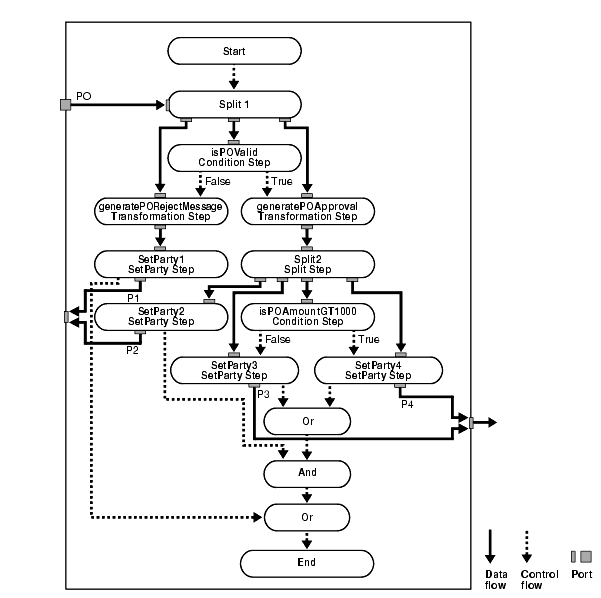
In Figure 12-27 shows the following details:
Table 12-12 shows the mutually exclusive and nonmutually exclusive paths in Figure 12-27.
If you want to connect all SetParty steps in Figure 12-27 to an End step, Table 12-13 describes the invalid possibilities.
If you want to connect all SetParty steps in Figure 12-27 to an End step, Table 12-14 describes the valid possibilities.
If all four SetParty steps in Figure 12-27 have their own outbound role port (named p1, p2, p3, p4), Table 12-15 describes valid and invalid methods for merging data flows from the step ports on to a role port.
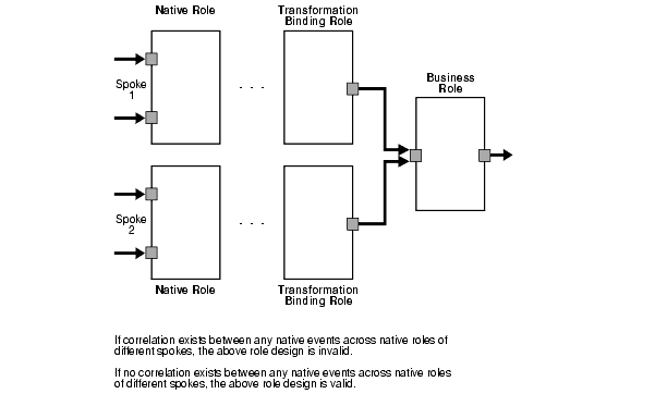
This section describes the invalid merging of data flows from role ports on different transformation binding roles (that is, different spokes) to one role port on a business role in the inbound direction.
Do not merge data flows coming from various spokes, whose corresponding native roles are correlated, to one inbound role port on the business role. This is to prevent repopulating of an already-populated inbound role port on the business role. Correlated native roles mean that it is possible for the two spokes to be part of one coordination at runtime. Therefore, the possibility exists for repopulating the business role port. Figure 12-28 shows this behavior.
There may be situations in which you know that given paths are mutually exclusive, but Oracle Application Server ProcessConnect does not. Oracle Application Server ProcessConnect therefore mandates that an And step be used in place of an Or step, which you may think is the correct choice. However, this action results in an infinite wait. In cases where this infinite wait cannot be avoided, design your steps so that this wait happens only at the End step and that there are no processing steps following this potentially indefinitely-waiting And step.
This results in the corresponding role instances not closing since their corresponding End steps have not executed. Consequently, the corresponding coordinations are also never closed. For these coordinations, you must explicitly close them through the Reports tab pages. Figure 12-29 shows this behavior:
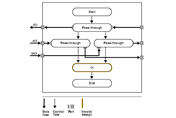
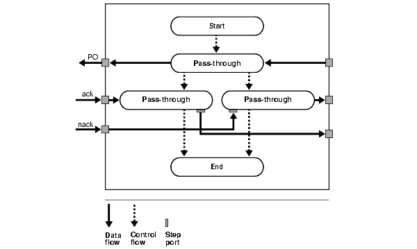
Assume only one of the ack or nack data flow always comes into Oracle Application Server ProcessConnect. There is currently no method in Oracle Application Server ProcessConnect to capture mutual exclusiveness properly across events entering Oracle Application Server ProcessConnect. Therefore, Oracle Application Server ProcessConnect assumes that both ack and nack always enter Oracle Application Server ProcessConnect. Consequently, Oracle Application Server ProcessConnect detects the design in Figure 12-29 as invalid. Figure 12-30 provides an example of how to validly design this situation without using an Or step.
This section describes the behavior of roles during runtime. This section contains these topics:
A coordination represents the execution of the business transaction represented by the business process. A coordination consists of the full set of role instances and event instances bound to a specific business process.
A native event instance is created from the wire message received by the adapter framework. As the event is processed by various roles in Oracle Application Server ProcessConnect, the appropriate role instances are created. The event can be translated into an application event instance and transformed into a business event instance before executing the business process.
The coordination is created when the initiating native event instance for the business process is raised by the adapter framework and picked up by the native role. As the event instance is being processed through the various roles, role instances are created for each of the role types in the business process. When a new native event is raised by the adapter framework, native event correlation is performed to match it with other native events that have been raised before this event.
There are two possibilities:
The coordination is automatically closed when all the role instances are complete and there are no event instances waiting to be processed on any of the role ports.
The coordination may not close in one of the following scenarios:
If all the events required by the business process have not been received; therefore, some of the steps have not been executed.
If there is an error during the execution of any steps. If there is a system error during processing of the event or datatype instance, the operation is automatically retried. If there is a domain error that has not been designed, then coordination processing halts. The step does not produce an event on its OUT port and there is a returnCode datatype with the error message on the return code port. In this case, Oracle Application Server ProcessConnect automatically aborts the coordination.
If there is an error in the way the roles have been designed, leading to a step that is waiting forever for data or events to appear. For example, if you have a condition step with two control flows (one for true and one for false), and these control flows are eventually connected to an AND step. In this case, there are mutually exclusive paths leading to an AND step, and this step never executes.
If the coordination is open and no new events are expected (as previously described in Scenario 1), then you can gracefully close the coordination from the Process Monitoring reports page in the design tool.
The coordination may also be open because of one of the error scenarios previously described in Scenario 2 and Scenario 3. In this case, the coordination must be aborted. This can be performed using the Process Monitoring reports page.
|
See Also:
|
If any errors occur during the processing of an event, Oracle Application Server ProcessConnect logs and handles the error depending on whether it is a system error or domain error.
|
See Also:
|
The following are common business process and role management user errors.
This chapter describes how to manage business processes and roles, which includes managing role types, role ports, role data flow, steps, step ports, step data flow, and step control flow, as well as managing condition expressions in steps. With condition steps, you can define an action based on the evaluation of an expression. Role design to ensure proper validation and the behavior of role during runtime are also discussed.
|
|
 Copyright © 2003 Oracle Corporation. All Rights Reserved. |
|