Chapter 4 Using eXchange Integrator in Enterprise Designer
This chapter provides step-by-step procedures for using the Enterprise Designer tools, editors, components, and prebuilt protocols and libraries provided by eXchange Integrator.
What’s in This Chapter
Overview
You use Enterprise Designer to set up the following:
-
Environments containing external servers, such as for Oracle and LDAP (required) and whichever transport protocols you use (File, BatchFTP, HTTP, and so forth).
-
One or more B2B Hosts configured with attribute definitions (metadata).
-
B2B Host projects, where each B2B Host is mapped to an Environment and built. Building a B2B Host project accomplishes two things:
-
Populates the LDAP database with metadata for the B2B Host.
-
Creates an eXchangeService that communicates with the Oracle database. The eXchangeService is itself used to connect with key business processes (BPs) and Java Collaborations (JCDs).
-
-
GUI projects — ePM and Tracker:
-
Building and deploying the ePM project creates an application, eXchange Partner Manager (ePM), that allows trading partner information to be viewing and updated via the Web.
-
Building and deploying the Tracker project creates another application (Message Tracker) that allows message data to be retained, retrieved, filtered, and viewed via the Web.
-
-
Error-handling projects:
Building and deploying the Sub_DLQ and Sub_ProcErrors projects is optional, but recommended. They take undeliverable messages (both “dead-letter” messages that cannot be parsed as well as poorly formed messages that do parse, but with errors) and write them into files for easy access and review.
-
Deployment projects:
Building and deploying a Deployment project connects the logic of your own business rules with the BPs and JCDs that constitute the core services of the B2B Suite (batching, delivery, error-handling, and so forth), through the mediation of the environment-specific eXchangeService.
Transaction Profiles
eXchange Integrator centers around the concept of a transaction profile for each trading partner relationship. Transaction profile information is stored on an LDAP-compliant directory server (usually called an LDAP server) through the following workflow:
-
Metadata for a transaction profile is defined in Enterprise Designer in the B2B Host.
-
Connecting the B2B Host to LDAP and building the B2B Host creates an eXchangeService and causes the metadata to be stored on LDAP.
-
Connecting the ePM GUI application to LDAP and building/deploying the application allows eXchange Partner Manager (ePM) to communicate with LDAP.
-
Values are eventually supplied using the eXchange Partner Manager (ePM) GUI, and activation of the trading partner produces transaction profiles stored on LDAP.
Using Enterprise Designer
You use Enterprise Designer to set up the B2B Host, connect it to LDAP, and build it. The B2B Host includes one or more sets of attribute definitions for protocol-related and transport parameters:
-
Business protocol attribute definitions (BPADs) that contain business and enveloping attribute definitions (BADs and EADs).
-
Delivery protocol attribute definitions (DPADs) contain messaging and packaging attribute definitions (MADs and PADs).
-
Transport attribute definitions are called TADs.
The business protocol manager applications available for eXchange Integrator, such as X12 or HIPAA, come equipped with prebuilt BPADs. You can also create your own BPADs for custom business protocols. Similarly for transport: You can use either the standard TADs supplied with eXchange Integrator (HTTP, FTP, ...) or create custom ones that you set up yourself.
After the B2B Host is set up with all its attribute definitions, a connectivity map is created to connect it to an LDAP server that is also connected to the ePM GUI. In the same connectivity map, the B2B Host is connected to an Oracle Server that is also connected to a Message Tracker application. Building the connectivity map causes the metadata to be stored on the LDAP server, and also creates an external, an eXchange Service, in the same Environment that contains the Oracle and LDAP externals.
For business logic, many prebuilt business processes BPs are supplied with eXchange Integrator to handle such B2B functions as batching, tracking, and dialogs. All of these BPs can be customized if you want. In addition, the eXchange Protocol Designer can be used to design and configure custom BPs that you create.
BPs for inbound and/or outbound messages are dragged into a connectivity map, where they are represented as services. There, they are connected in usual fashion with externals (including the eXchangeService) and with other services. Activation of a corresponding Deployment Profile exposes the connectivity map’s components for processing by Logical Hosts. All information is stored to LDAP, thus making it available for viewing or modification by ePM.
B2B Host Procedures
The chapter provides information on the following procedures:
-
Steps for creating a B2B Host and populating it with attribute definitions.
-
Steps for configuring the external systems in the environment, including the B2B Configurator.
-
Optional steps for creating and configuring custom attribute definitions.
-
Steps for building a B2B Host connected to an LDAP external and an Oracle external, thus creating the eXchangeService.
-
Steps for building and deploying projects for the GUI and for error-handling.
Setting Up a B2B Host and Its Components
This section explains how to create a B2B Host and populate it with attribute definitions. The editor used for configuring B2B Hosts is the B2B Host Designer.
 To create a B2B host
-
In Enterprise Designer with the Project Explorer tab active, in the project tree, right-click the Project or subproject where the B2B Host will reside.
-
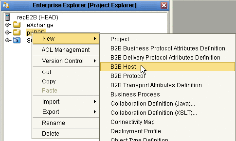
Point to New and click B2B Host.
See Figure 4–1.
Figure 4–1 Creating a New B2B Host
-
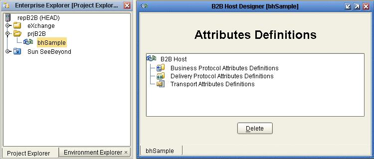
When the new component appears in the project tree, you can click-pause-click to rename it from B2BHost1 to whatever you want.
It is good practice to use a short name beginning with “bh” to indicate that the component is a B2B Host.
The project tree displays the new component with a “handshake” icon. Also, the B2B Host Designer opens to display a tree of Attribute Definitions, with containers for Business Protocol Attribute Definitions, Delivery Protocol Attribute Definitions, and Transport Attribute Definitions. See Figure 4–2.
Figure 4–2 B2B Host Designer
To populate a B2B host with attribute definitions
-
For custom BPADs, DPADs, or TADs: Open the project or subproject and drag the attributes definition into the Attribute Definitions window. Repeat as needed for other custom attribute definitions.
-
For presupplied attribute definitions: In the project explorer tree, open the SeeBeyond⇒eXchange folder, and do the following as appropriate:
-
For X12: Open the Protocol Managers⇒ X12 Manager⇒OTDs folder and drag the X12 BPAD into the B2B Host Designer window.
-
For HIPAA: Open the Protocol Managers⇒HIPAA Manager⇒OTDs folder and drag the HIPAA BPAD into the B2B Host Designer window.
-
For standard transports: Open the Transport Attribute Definitions folder and drag one or more TADs into the B2B Host Designer window.
-
Figure 4–3 Business Protocols Window Showing Pre-supplied BPADs and TADs
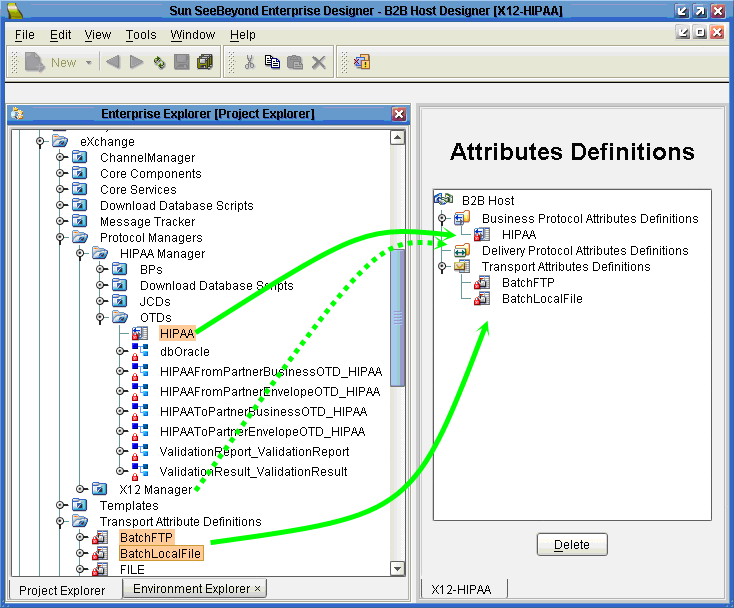
Figure 4–3 shows a B2B Host populated with attribute definitions. You can combine several protocols in one B2B Host, and you can combine custom BPADs, DPADs, and TADs with standard ones.
Setting Up Attribute Definitions
This section explains how to create and configure custom attribute definitions:
Creating and Configuring TADs
In general, a protocol is a code of behavior: a framework for interpretation and communication that is agreed upon by all parties. It specifies rules for interacting with others who are using the same protocol.
A transport protocol provides a way of specifying how data is to be delivered from one system to another. For example, FTP (file transfer protocol) requires the client to specify a transfer mode (such as ASCII or binary), a target directory, a target filename or file pattern, and so forth. In eXchange Integrator, these parameters are specified by the standard transport attributions definition for FTP. eXchange Integrator supplies attribute definitions for the following standard transport protocols: BatchFTP, BatchLocalFile, File, FTP, HTTP, HTTPS, JMS, and SMTP.
In addition to the attribute definitions for the standard transport protocols noted above, you can use custom transport attribute definitions that specify custom modifications or extensions of the standard transport protocols.
 To create a custom transport attributes definition
-
In Enterprise Designer with the Project Explorer tab active, in the project tree, right-click the project or subproject where the transport attributes definition will reside.
-
On the context menu, point to New, and click B2B Transport Attributes Definition.
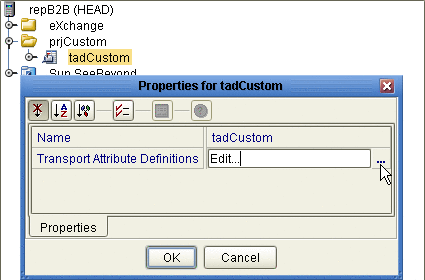
The project tree displays the new component, and a properties dialog allows you to edit the attribute definitions. See Figure 4–4. It is good practice to rename it from B2BTransportAttributesDefinition n to a meaningful short name beginning with tad to indicate that the component is a Transport Attributes Definition.
Figure 4–4 Custom Transport Attributes Definition
This new component is useful only by virtue of its configuration — you need to add and define attributes that govern the nodes in the OTD that are generated from it. Once attributes are defined, they can be exposed to eXchange Partner Manager (ePM) for delivery channel configuration.
 To configure a custom transport attributes
definition
-
In the project tree, right-click the transport attributes definition you want to modify, and click Properties, and then click Edit.
Note –If the component is locked, you must check it out before you can modify it.
-
In the properties dialog, to the far right of the value for Transport Attribute Definitions, click the ellipsis [...] button
The Attributes dialog appears. Figure 4–5 shows attributes for a sample bidirectional transport attributes definition that is a modification of the basic File TAD.
Figure 4–5 Custom Attribute Definitions
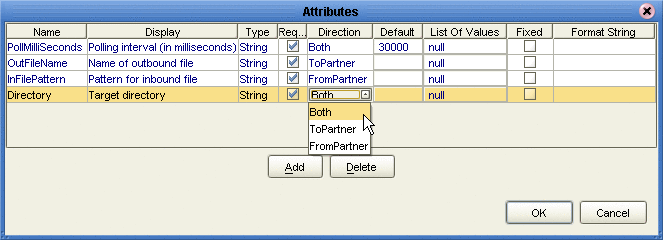
You use this dialog to create and set attributes. These values govern the appearance and behavior of the parameters displayed in ePM when configuring external delivery channels for a trading partner profile, in the ToPartner Transport and FromPartner Transport subtabs.
-
Click the Add button as many times as needed and then, for each row created:
-
Change Name to a meaningful node name for the OTD you will generate.
-
Change Display to the text you want to display as a prompt or label for the parameter in ePM.
-
For Type, select the data type for this attribute:
-
String (the default) allows the ePM user to enter any character data
-
Password accepts any ePM input, and masks the input
-
Integer accepts positive or negative whole numbers only
-
Number extends this to also accept decimal numbers (floating-point numbers)
-
Boolean requires the ePM user to make a yes-or-no choice
-
List of Values presents the ePM user with a drop-down list restricted to the items you have set up
-
DateTime prompts the ePM user to supply a date and/or time value, based on the formatting you provide
-
-
For Required, select or clear the box according to whether you want the parameter to be a required or optional entry. (In the ePM GUI, parameters that have been designated as required are flagged with a red asterisk.)
-
For Direction, choose ToPartner, FromPartner, or Both according to whether you want the parameter to appear with the ToPartner parameters, FromPartner parameters, or both.
-
For Default, you can optionally enter a default value to appear in ePM before the user enters data or makes a selection. This is the value that is used if it is not overridden by the ePM user.
-
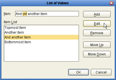
For List of Values, which is available only for an attribute whose data type is “List of Values”, double-click the ellipsis [...] button to the far right and use the List of Values dialog box to add entries to the drop-down list that is seen by the end user:
-
Add appends a new item to the end of the list
-
Edit allows you to modify the currently selected item
-
Move Up and Move Down move it higher or lower in the list. See Figure 4–6.
-
Figure 4–6 Attributes Definition - List of Values
-
Format String allows you to use special characters as shorthand for certain often-used information; for example, %f is the working filename, %M is the current month, %d the current day, and so forth. For more information, see the eWay Batch Adapter User’s Guide. The chapter on understanding OTDs has a section on using special characters.
-
-
When you have finished adding and modifying attributes, click OK.
-
Click OK to close the properties dialog.
The completed TAD can be dragged into the B2B Host. After other steps are also completed, the metadata in its attribute definitions are stored on the LDAP server, and the parameters it defines appear in eXchange Partner Manager (ePM).
Creating and Configuring DPADs
Delivery protocol attribute definitions, or DPADs, are used by delivery protocols such as AS2 and ebXML. DPADs consist of messaging attribute definitions (MADs) and packaging attribute definitions (PADs). If you do not use delivery protocols, your B2B Host does not need to define any DPADs.
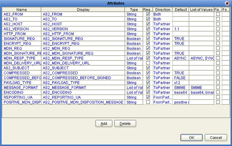
Generally, DPADs provide a way of specifying how data is bundled and unbundled — for example, in AS2 and ebXML, it is at this level that encryption, acknowledgment, and nonrepudiation are addressed. Figure 4–7 provides an example of the MAD for AS2 version 1.1.
Figure 4–7 Default Messaging Attributes Definition (MAD) for AS2 v1.1
 To create a new DPAD
-
In Enterprise Designer with the Project Explorer tab active, in the project tree, right-click the project or subproject where the DPAD will reside.
-
On the popup context menu, point to New, and click B2B Delivery Protocol Attributes Definition.
-
In the properties, enter a name (good practice is to enter a short name beginning with “dpad”, such as dpadCustom1) and click OK.
The project tree displays the new component.
This new component is useful only by virtue of its configuration — you need to add name/value pairs for the parameters you want it to define.
 To configure a DPAD
-
In Enterprise Designer, with the Project Explorer tab active, right-click the DPAD you want to modify, and then click Properties⇒Edit.
Note –If the component is locked, you must check it out before you can modify it.
-
To the far right of the value for Messaging Attribute Definitions, click the ellipsis [...] button.
The Messaging Attribute Definitions dialog appears. You use this dialog to create and set the messaging attributes.
-
Click the Add button as many times as needed and then, for each row created:
-
Change Name to a meaningful node name for the OTD you will generate.
-
Change Display to the text you want to display as a prompt or label for the parameter in ePM.
-
For Type, select the data type for this attribute:
-
String (the default) allows the ePM user to enter any character data
-
Password accepts any ePM input, and masks the input
-
Integer accepts positive or negative whole numbers only
-
Number extends this to also accept decimal numbers (floating-point numbers)
-
Boolean requires the ePM user to make a yes-or-no choice
-
List of Values presents the ePM user with a drop-down list restricted to the items you have set up
-
DateTime prompts the ePM user to supply a date and/or time value, based on the formatting you provide
-
Format String allows you to use special characters as shorthand for certain often-used information; for example, %f is the working filename, %M is the current month, %d the current day, and so forth. For more information, see the eWay Batch Adapter User’s Guide. The chapter on understanding OTDs has a section on using special characters.
-
-
For Required, select or clear the box according to whether you want the parameter to be a required or optional entry. (In the ePM GUI, parameters that have been designated as required are flagged with a red asterisk.)
-
For Direction, choose ToPartner, FromPartner, or Both according to whether you want the parameter to appear with the ToPartner parameters, FromPartner parameters, or both.
-
For Default, you can optionally enter a default value to appear in ePM before the user enters data or makes a selection. This is the value that is used if it is not overridden by the ePM user.
-
For List of Values, which is available only for an attribute whose data type is “List of Values”, double-click the ellipsis [...] button to the far right and use the List of Values dialog box to add entries to the drop-down list that is seen by the end user:
-
a new item to the end of the list
-
Edit modifies the currently selected item
-
Up and Down move it higher or lower in the list
-
-
-
When you have finished adding and modifying attributes, click OK.
-
Repeat the corresponding steps for the packaging attributes definition (PAD).
-
Click OK to close the properties dialog.
The DPAD can now be used to generate an OTD.
After you have completed these steps, the DPAD appears as a choice in the drop-down list of DPADs when you configure the delivery protocols of your B2B Host.
Creating and Configuring BPADs
Business protocol attribute definitions (BPADs) consist of business attribute definitions (BADs) and enveloping attribute definitions (EADs). BPADs are used by business protocols, such as X12, HIPAA, and EDIFACT. If you do not use business protocols, your B2B Host does not need to define any BPADs.
Generally, BADs specify business protocol parameters at the group level (that is, the inner envelope), and EADs specify business protocol parameters at the interchange level (that is, the outer envelope).
Figure 4–8 provides examples of a BAD for X12 (named “X12”) and a BAD for EDIFACT (named “EDIFACT-UNG”). The attributes in the BAD specify the label, type, and so forth of parameters that are displayed in ePM.
Figure 4–8 Default Business Attribute Definitions (BADs) for X12 and EDIFACT
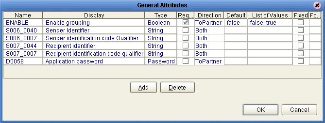
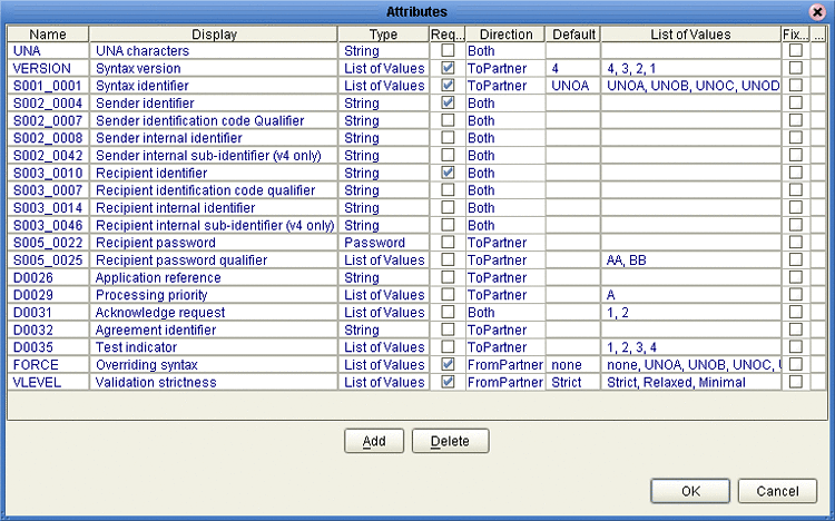
Figure 4–9 provides examples of an EAD for X12 (named “Envelope”) and an EAD for EDIFACT (named “EDIFACT-UNB”). The attributes in the EAD specify the label, type, and so forth for parameters that are displayed in ePM.
Figure 4–9 Default Enveloping Attribute Definitions (EADs) for X12 and EDIFACT
You can also create custom BPADs, either from scratch or by modifying/extending the versions shipped with X12 or HIPAA protocol managers.
 To create a BPAD
-
In Enterprise Designer with the Project Explorer tab active, in the project tree, right-click the project or subproject where the BPAD will reside.
-
On the context menu, point to New, and click B2B Business Protocol Attributes Definition.
-
In the properties, enter a name (good practice is to enter a short name beginning with “bpad”, such as bpadCustom1) and click OK.
The project tree displays the new component.
This new component is useful only by virtue of its configuration — you need to add name/value pairs for the parameters you want it to define.
 To configure a BPAD
-
In Enterprise Designer, with the Project Explorer tab active, right-click the BPAD you want to modify.
Note –If the component is locked, you must check it out before you can modify it.
-
To the far right of the value for Envelope Attribute Definitions, click the ellipsis [...] button to display the Envelope Attribute Definitions dialog box.
See Figure 4–10.
Figure 4–10 Accessing a BPAD’s Envelope Attribute Definitions (EAD)
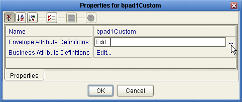
You use this dialog box to create and set the envelope attribute definitions (EAD) of the current BPAD.
-
Click the Add button as many times as needed (a four-row EAD is illustrated in Figure 4–11) and then, for each row created:
-
Change Name to a meaningful node name for the OTD you will generate.
-
Change Display to the text you want to display as a prompt or label for the parameter in ePM.
-
For Type, select the data type for this attribute:
-
String (the default) allows the ePM user to enter any character data
-
Password accepts any ePM input, and masks the input
-
Integer accepts positive or negative whole numbers only
-
Number extends this to also accept decimal numbers (floating-point numbers)
-
Boolean requires the ePM user to make a yes-or-no choice
-
List of Values presents the ePM user with a drop-down list restricted to the items you have set up
-
DateTime prompts the ePM user to supply a date and/or time value, based on the formatting you provide
-
-
For Required, select or clear the box according to whether you want the parameter to be a required or optional entry. (In the ePM GUI, parameters that have been designated as required are flagged with a red asterisk.)
-
For Direction, choose ToPartner, FromPartner, or Both according to whether you want the parameter to appear with the ToPartner parameters, FromPartner parameters, or both.
-
For Default, you can optionally enter a default value to appear in ePM before the user enters data or makes a selection. This is the value that is used if it is not overridden by the ePM user.
-
For List of Values, which is available only for an attribute whose data type is “List of Values”, double-click the ellipsis [...] button to the far right and use the List of Values dialog box to add entries to the drop-down list that is seen by the end user:
-
Add appends a new item to the end of the list
-
Edit modifies the currently selected item
-
Up and Down move it higher or lower in the list
-
-
Format String allows you to use special characters as shorthand for certain often-used information; for example, %f is the working filename, %M is the current month, %d the current day, and so forth. For more information, see the eWay Batch Adapter User’s Guide. The chapter on understanding OTDs has a section on using special characters.
-
Figure 4–11 Custom Envelope Attribute Definitions (EAD)

-
-
When you have finished adding and modifying envelope attributes, click OK.
-
Repeat the corresponding steps for the business attributes definition (BAD).
-
Click OK to close the properties dialog.
The BPAD can now be used to generate an OTD.
After you have completed these steps, the BPAD appears as a choice in the drop-down list of BPADs when you configure the delivery protocols of your B2B Host.
After you have completed these steps, activation of the B2B Host causes the BPAD parameters (that is, the ones you defined for the EAD and the BAD) to appear in ePM.
Building a B2B Host
The B2B host plays a dual role: It functions both as an object — that is, a project-level (logical) component in the project tree that can be dragged into a Connectivity Map —, and also as a server — that is, an environment (physical) component, called eXchangeService.
Each B2B Host project joins a particular B2B Host instance to a particular Environment. The name of the created eXchangeService reflects this: For example, if the B2B Host instance is named cm1myHost123, and the Environment is named envA, the name of the new external added to the Environment is envA_cm1myHost123 eXchange Service.
Creating an Environment
These steps below set up the minimal environment required for building a B2B Host that can be used by eXchange Partner Manager (ePM).
 To create and populate the environment
-
In Enterprise Designer with the Environment Explorer tab active, right-click the Repository.
The explorer tree displays a new environment, and the Environment Editor opens. Optionally, you can rename the environment to something meaningful.
-
On the context menu, click New Environment.
-
In the environment explorer tree, right-click the new environment.
-
On the context menu, point to New and click Logical Host.
The explorer tree and editor canvas display the new Logical Host. Optionally, you can use the tree to rename the Logical Host to something meaningful.
-
In the environment explorer tree, right-click the new Logical Host.
-
On the context menu, point to New and click Sun SeeBeyond Integration Server.
The explorer tree displays the new Integration Server, and the canvas displays it inside the Logical Host. Optionally, you can rename it to something meaningful.
-
If appropriate, right-click the Integration Server, click Properties, and configure its parameters as needed for use at your site.
-
In the environment explorer tree, right-click the new Logical Host.
-
On the context menu, point to New and click Sun SeeBeyond JMS IQ Manager.
The explorer tree displays the new JMS IQ Manager, and the canvas displays it inside the Logical Host. Optionally, you can rename it to something meaningful.
-
If appropriate, right-click the JMS IQ Manager, click Properties, and configure its parameters as needed for use at your site.
 Creating and configuring the Oracle external
-
In the environment explorer tree, right-click the environment.
-
On the context menu, point to New and click Oracle External System.
-
In the Create an External System dialog, enter a meaningful name, set the system type to Outbound Oracle eWay, and click OK.
-
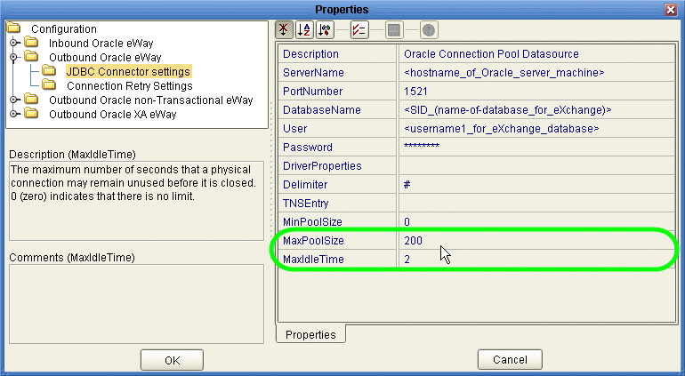
Configure the Oracle external with the values for your eXchange database instance.
For details on configuring the Oracle external, see the Oracle eWay User’s Guide. For sample settings typical of an eXchange database, see Figure 4–12.
Figure 4–12 Environment Configuration for Oracle External System
-
In the environment explorer tree, right-click the environment.
-
On the context menu, point to New and click B2BServiceConfigurator External System.
-
In the Please input the name dialog, enter a meaningful name and click OK.
-
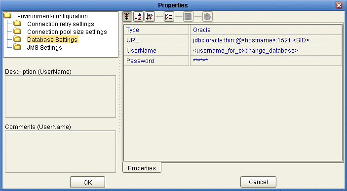
Open the properties of the B2BService Configurator and, for Database Settings, supply values for URL, UserName, and Password that match the values you supplied for the Oracle external.
See Figure 4–13.
Figure 4–13 Environment Configuration for Oracle External System
 Creating and configuring LDAP
and other externals
-
In similar fashion, create an external system for LDAP, name it appropriately, and configure it appropriately for your operating environment.
-
Also create external systems for BatchFTP, BatchLocalFile, File, and HTTP (as well as any other external systems corresponding to other transport protocols used by your B2B Host), and configure them appropriately for your operating environment.
Once you finish these steps, the environment now has all you need to build a B2B Host as well as the GUI, Tracker, and error-handling projects.
To create the eXchange Service, you create a connectivity map that links the B2B Host to an Oracle eWay and then build the corresponding Deployment Profile. See Connecting the B2B Host to Oracle and LDAP Externals.
Optional: Configuring an Environment to Use HTTPS
HTTPS means “HTTP over SSL” (secure sockets layer). If you want to use the HTTPS transport attributes definition, you must take additional steps to enable HTTPS.
-
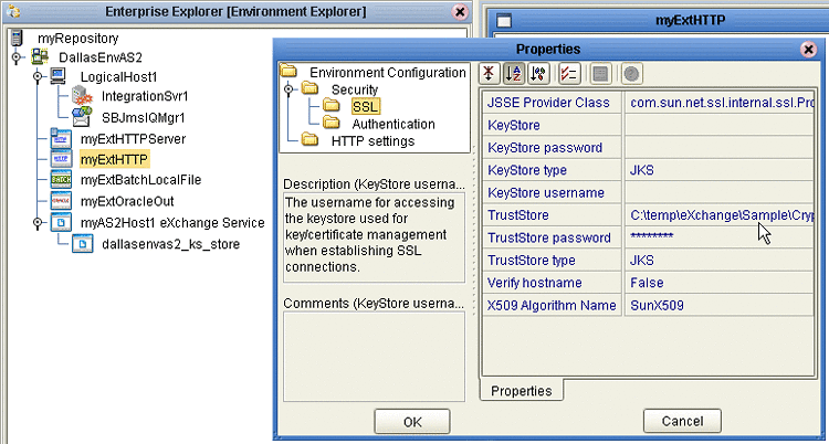
To enable an HTTP external to use SSL, it must have its SSL configuration settings edited appropriately. For more information, See the eWay HTTPS Adapter User’s Guide. For an example of settings specific to eXchange Integrator, see the To configure the HTTP external to use SSL.
-
To enable the Integration Server to communicate using HTTPS, it needs to be associated with appropriate configuration settings. fore more information, see the eGate Integrator System Administration Guide.
 To configure the HTTP external to use SSL
-
In the Environment Explorer tree, right-click the HTTP external and, on the popup context menu, click Properties.
-
In the Properties sheet, open Security and click SSL.
-
For TrustStore, provide the path and filename of the default truststore to be used when establishing SSL connections; for example:
C:\temp\eXchange\Crypto\companyb.ssl.keystore
-
For TrustStore password, provide the correct password for this truststore; for example: companyb.
For TrustStoreType, keep the default: JKS. See Figure 4–14.
Figure 4–14 Configuring the SSL Properties of the HTTP External
-
AIX only. Make the following additional changes for Logical Hosts running on AIX.
-
Change JSSE Provider Class from com.sun.net.ssl.internal.ssl.Provider to: com.ibm.jsse.IBMJSSEProvider
-
Change X509 Algorithm Name from SunX509 to (case-sensitive): IbmX509
-
Also make other configuration changes as needed. For more information, see the eWay HTTPS Adapter User’s Guide.
-
When you are finished, click OK.
Note –Before you start the domain, ensure that its ...\keystore\ directory contains the correct .keystore file and that its alias (unless you edit server.xml otherwise) is tomcat. For an example, copy jc512-repository \server\sbyn.keystore to your jc512-logicalhost\keystore\ directory and rename it from sbyn.keystore to yourIntegrationServername .keystore. The keystore file must be of type JKS.
-
-
Connecting the B2B Host to Oracle and LDAP Externals
These steps create a map that establishes a connection between the B2B Host and the two externals the B2BService communicates with: Oracle and LDAP.
 To create and populate the B2B Host Connectivity
Map
-
With the Project Explorer tab active, in the project tree, right-click the project.
-
On the context menu, point to click New and click Connectivity Map.
The project tree displays a new map, and the Connectivity Map Editor opens. Optionally, you can rename the map to something meaningful.
-
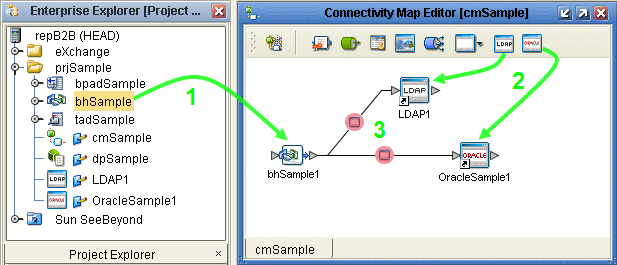
In the toolbar along the top of the canvas, click the External Applications tool and, from the drop-down list, select the checkboxes for Oracle External Application and for LDAP External Application.
-
From the project tree, drag your B2B Host onto the left side of the canvas
-
From the toolbar, do the following:
-
Drag an Oracle external onto the right side of the canvas.
-
Drag and LDAP external onto the right side of the canvas.
Optionally, you can rename components to something meaningful, and then connect them. See Figure 4–15.
Figure 4–15 Connectivity Map Showing B2B Host Connected to Externals
-
-
For the B2B-LDAP connection: double-click the pink dot.
-
When the Properties dialog box appears, make no changes, but click OK to set the default configuration.
-
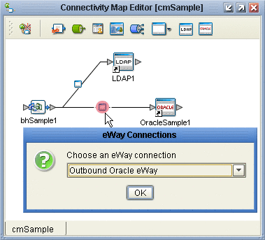
For the B2B-Oracle connection: double-click the pink dot and configure the Oracle eWay as outbound.
See Figure 4–16.
Figure 4–16 Configuring the Oracle External as Outbound
-
When the Properties dialog box appears, make no changes, but click OK to set the default configuration.
Now that the map is populated and configured, you are ready to build the B2B Host.
Building the B2B Host
These steps create, populate, and build a Deployment Profile that maps the resources named in the Connectivity Map to the resources provided in an Environment.
 To create and build the Deployment Profile for the B2B
Host
-
With the Project Explorer tab active, in the project tree, right-click the project.
-
On the context menu, point to New and click Deployment Profile.
-
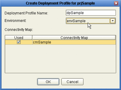
In the Create Deployment Profile dialog box, rename the deployment profile to something meaningful, point it at the correct Environment.
Make sure that it is referencing the Connectivity Map that contains the B2B Host. See Figure 4–17.
Figure 4–17 Creating the Deployment Profile for the B2B Host Project
-
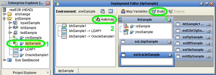
In the Deployment Editor, click Automap to map the three components to their respective external systems.
See Figure 4–18.
Figure 4–18 Deployment Profile Before Components Are Mapped to Externals
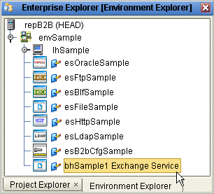
In the Environment targeted by the Deployment Profile, an eXchangeService is added that contains all the metadata of the B2B Host. See Figure 4–19.
Figure 4–19 Environment with Newly Created eXchangeService
-
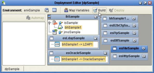
Click Build.
See Figure 4–20.
Figure 4–20 Deployment Profile Build in Progress
Building and Deploying the GUI Projects
These procedures build and deploy Deployment Profiles that map the resources named in the cmEpm and cmTracker Connectivity Maps to the externals in an Environment. The cmEpm map associates the epm application with an LDAP server. The cmTracker map associates the epm application with an Oracle server. See Figure 4–21.
Figure 4–21 Connectivity Maps for ePM and Tracker
 Before you begin
-
With the Project Explorer tab active, in the project tree, open the eXchange⇒GUI project.
-
If you have not already done so, start the domain associated with the Environment’s Integration Server.
 To build and deploy the Deployment Profile for the ePM
Project
-
In the project tree, under eXchange⇒GUI⇒ePM, open cmEpm and configure its LDAP eWay appropriately for your operating environment.
-
Right-click the ePM project.a
-
On the context menu, point to New and click Deployment Profile.
-
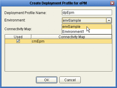
In the Create Deployment Profile dialog box, name the Deployment Profile to dpEpm, and point it at the correct Environment.
-
Make sure that it is referencing cmEpm (the Connectivity Map for the ePM GUI), and then click OK.
See Figure 4–22.
Figure 4–22 Deployment Profile for ePM Project
-
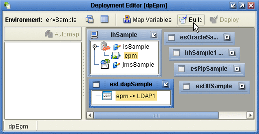
In the Deployment Editor, click Automap to map the two components to their respective external systems, and then click Build.
See Figure 4–23.
Figure 4–23 Deployment Profile dpEpm Being Built
-
After the build step completes successfully (creating the EAR file), click Deploy.
The ePM GUI project is built and deployed,. You can now use eXchange Partner Manager. Message Tracker becomes available only after you build and deploy its Project.
 To build and deploy the Deployment Profile for the Tracker
Project
-
In the project tree, under eXchange⇒ GUI, right-click the Tracker project.
-
On the context menu, point to New and click Deployment Profile.
-
In the Create Deployment Profile dialog box, name the Deployment Profile to dpTracker and point it at the correct Environment.
-
Make sure that it is referencing cmTracker (the Connectivity Map for the Message Tracker GUI), and then click OK.
-
In the Deployment Editor, click Automap to map the two components to their respective external systems, and then click Build.
-
After the build step completes successfully (creating the EAR file), click Deploy.
See Figure 4–24.
Figure 4–24 Deployment Profile dpTracker Being Deployed
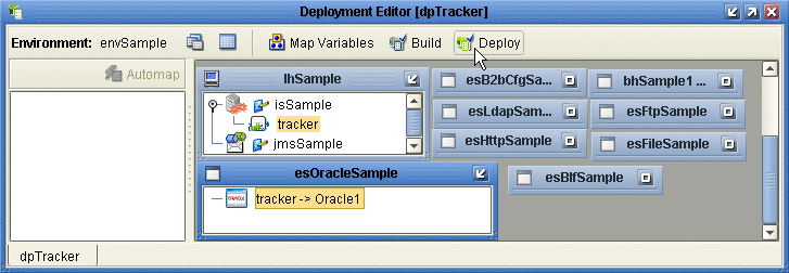
The Message Tracker GUI project is built and deployed, and the Message Tracker application is now able to store and retrieve messages.
Building and Deploying the Error-Handling Projects
These procedures build and deploy Deployment Profiles that map the resources named in the cmSub_DLQ and cmSub_ProcErrors Connectivity Maps to the externals in an Environment. The cmSub_DLQ map uses a BP to receive messages from the JMS topic EX_DEADLETTER (sometimes called the “dead letter queue”) and write them to a file. The cmSub_ProcErrors map uses a BP to receive messages from the JMS topic EX_PROCESSEDERRORS and write them to a file.
 Before you begin
-
With the Project Explorer tab active, in the project tree, open the eXchange⇒Errors project.
-
If you have not already done so, start the domain associated with the Environment’s Integration Server.
 To build and deploy the Deployment Profile for the Sub_DLQ
Project
-
In the project tree, under eXchange⇒Errors⇒Sub_DLQ, open cmSub_DLQ and make sure that its File eWay is configured appropriately for your operating environment.
-
Right-click the Sub_DLQ project.
-
On the context menu, point to New and click Deployment Profile
-
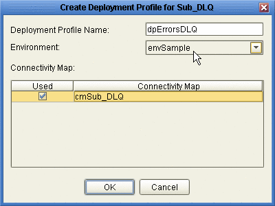
In the Create Deployment Profile dialog box, name the Deployment Profile to dpErrorsDLQ and point it at the correct Environment.
-
Make sure that it is referencing cmSub_DLQ (the Connectivity Map for the “dead letter” topic), and then click OK.
See Figure 4–25.
Figure 4–25 Deployment Profile for Sub_DLQ Project
-
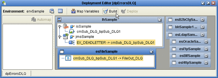
In the Deployment Editor, click Automap to map the two components to their respective external systems, and then click Build.
See Figure 4–26.
Figure 4–26 Deployment Profile dpErrorsDLQ Being Built
-
After the build step completes successfully (creating the EAR file), click Deploy.
The Sub_DLQ project is built and deployed. At runtime, any undeliverable messages that cannot be processed are copied and written to a file.
 To build and deploy the Deployment Profile for the Sub_ProcErrors
Project
-
In the project tree, under eXchange⇒Errors⇒Sub_ProcErrors, open cmSub_ProcErrors and make sure that its File eWay is configured appropriately for your operating environment.
-
Right-click the Sub_ProcErrors project.
-
On the context menu, point to New and click Deployment Profile.
-
In the Create Deployment Profile dialog box, name the Deployment Profile to dpErrorsProc and point it at the correct Environment.
-
Make sure that it is referencing cmSub_ProcErrors (the Connectivity Map for the “processed errors” topic), and then click OK.
-
In the Deployment Editor, click Automap to map the two components to their respective external systems, and then click Build.
-
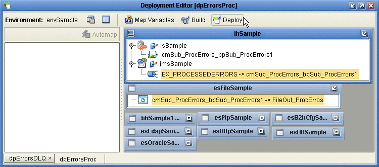
After the build step completes successfully (creating the EAR file), click Deploy.
See Figure 4–27.
Figure 4–27 Deployment Profile dpErrorsProc Being Deployed
The Sub_ProcErrors project is built and deployed. At runtime, undeliverable messages written to the processed-errors topic are copied and written to a file.
- © 2010, Oracle Corporation and/or its affiliates
