SWIFT Projects and the Enterprise Designer
A Project contains all of the eGate components that you designate to perform one or more desired processes in eGate.
-
Connectivity Map Editor: contains the eGate business logic components, such as Collaborations, Topics, Queues, and eWays, that you include in the structure of the Project.
-
OTD Editor: contains the source files used to create Object Type Definitions (OTDs) to use with a Project.
-
Business Process Designer and Editor: allows you to create and/or modify Business Rules to implement the business logic of your Project’s eInsight Business Processes.
-
Java Collaboration Editor: allows you to create and/or modify Business Rules to implement the business logic of your Project’s Java Collaboration Definitions.
SWIFT Sample prjSwift_JCD_MFVROnly Project
The SWIFT Sample Project (prjSwift_JCD_MFVROnly) demonstrates the validation features of the SWIFT OTD Library for MFVR only. Specifically, this Project employs the Java-based Validation Collaborations and their definitions.
The Project uses a common process infrastructure to identify and isolate invalid messages. The process keeps these messages readily available for further use. It also passes valid messages on to their destinations. .
Project Walkthrough
The flow of the Project is as follows:
-
The inbound File eWay subscribes to an external ”input” directory. The eWay accepts an MT_541 message and publishes it to the Service1 Collaboration.
-
The CopyCollab1 service (CopyCollaboration) unmarshals the message, copies all of the data fields (to demonstrate how to copy the data fields), marshals the message to a String and publishes the message to a JMS Queue.
-
The ValidateMT_541 Collaboration accepts the message from the JMS Queue, validates the message, and publishes it to the ValidMessage Queue if the message is valid, or to the InvalidMessages if the message is not valid.
-
The PrintValidMessages Collaboration accepts the valid messages, prints out the message and sends the message to the outbound File eWay.
-
The PrintInvalidMessages Collaboration accepts the invalid messages, prints that the message is invalid and lists any errors. It then sends that message to the outbound File eWay.
-
The outbound File eWay publishes the messages to an external folder as either Swift2008_JCD_MFVROnly_Valid_output1.dat or Swift2008_JCD_MFVROnly_Invalid_output1.dat.
You must name the source (input) and destination (output) file directories in the setting property settings for the Project’s File eWays. See the File eWay Intelligent Adapter User’s Guide for details.
SWIFT Sample prjSwift_JCD_MFVROnly Project Data
Sample valid and invalid input messages are provided with the downloaded sample, as well as examples of valid and invalid output messages. These are located in the SWIFT sample project folder as follows:
-
input_Swift2008JCD_MFVROnly_Validmt541.txt.~in: sample valid message input file
-
input_Swift2008JCD_MFVROnly_Invalidmt541.txt.~in: sample invalid message input file
-
Swift2008_JCD_MFVROnly_Valid_output1.dat: example of sample valid message output
-
Swift2008_JCD_MFVROnly_Invalid_output1.dat: example of sample invalid message output
Also, see Validation Operation for a more detailed explanation of the validation operation.
SWIFT Sample prjSwift_JCD_MFVRAndBICPlusIBAN Project
The SWIFT Sample Project (prjSwift_JCD_MFVRAndBICPlusIBAN) demonstrates the validation features of the SWIFT OTD Library for the combination of MFVR and BIC/IBAN. Specifically, this Project employs the Java-based Validation Collaborations and their definitions.
The Project uses a common process infrastructure to identify and isolate invalid messages. The process keeps these messages readily available for further use. It also passes valid messages on to their destinations. .
Project Walkthrough
The flow of the Project is as follows:
-
The inbound File eWay subscribes to an external ”input” directory. The eWay accepts an MT_541 message and publishes it to the Service1 Collaboration.
-
The CopyCollab1 service (CopyCollaboration) unmarshals the message, copies all of the data fields (to demonstrate how to copy the data fields), marshals the message to a String and publishes the message to a JMS Queue.
-
The ValidateMT_541_Modified Collaboration accepts the message from the JMS Queue, validates the messages for MFVR and then for BICPlusIBAN, and publishes it to the ValidMessage Queue if the message is valid, or to the InvalidMessages if the message is not valid.
-
The PrintValidMessages Collaboration accepts the valid messages, prints out the message and sends the message to the outbound File eWay.
-
The PrintInvalidMessages Collaboration accepts the invalid messages, prints that the message is invalid and lists any errors. It then sends that message to the outbound File eWay.
-
The outbound File eWay publishes the messages to an external folder as either Swift2008_JCD_MFVRAndBICPlusIBAN_Valid_output1.dat or Swift2008_JCD_MFVRAndBICPlusIBAN_Invalid_output1.dat.
You must name the source (input) and destination (output) file directories in the setting property settings for the Project’s File eWays. See the File eWay Intelligent Adapter User’s Guide for details.
SWIFT Sample prjSwift_JCD_MFVRAndBICPlusIBAN Project Data
Sample valid and invalid input messages are provided with the downloaded sample, as well as examples of valid and invalid output messages. These are located in the SWIFT sample project folder as follows:
-
input_Swift2008JCD_MFVR_BICPlusIBAN_Validmt541.txt.~in: sample valid message input file
-
input_Swift2008JCD_MFVR_BICPlusIBAN_Invalidmt541.txt.~in: sample invalid message input file
-
Swift2008_JCD_MFVRAndBICPlusIBAN_Valid_output1.dat: example of sample valid message output
-
Swift2008_JCD_MFVRAndBICPlusIBAN_Invalid_output1.dat: example of sample invalid message output
Also, see Validation Operation for a more detailed explanation of the validation operation.
SWIFT Sample prjSwift_JCD_BICPlusIBANOnly Project
The SWIFT Sample Project (prjSwift_JCD_BICPlusIBANOnly) demonstrates the validation features of the SWIFT OTD Library for BIC and IBAN only. Specifically, this Project employs the Java-based Validation Collaborations and their definitions.
The Project uses a common process infrastructure to identify and isolate invalid messages. The process keeps these messages readily available for further use. It also passes valid messages on to their destinations. .
Project Walkthrough
The flow of the Project is as follows:
-
The inbound File eWay subscribes to an external ”input” directory. The eWay accepts an MT_541 message and publishes it to the Service1 Collaboration.
-
The CopyCollab1 service (CopyCollaboration) unmarshals the message, copies all of the data fields (to demonstrate how to copy the data fields), marshals the message to a String and publishes the message to a JMS Queue.
-
The ValidateMT_541_Modified Collaboration accepts the message from the JMS Queue, validates the messages for BICPlusIBAN only, and publishes it to the ValidMessage Queue if the message is valid, or to the InvalidMessages if the message is not valid.
-
The PrintValidMessages Collaboration accepts the valid messages, prints out the message and sends the message to the outbound File eWay.
-
The PrintInvalidMessages Collaboration accepts the invalid messages, prints that the message is invalid and lists any errors. It then sends that message to the outbound File eWay.
-
The outbound File eWay publishes the messages to an external folder as either Swift2008_JCD_BICPlusIBANOnly_Valid_output1.dat or Swift2008_JCD_BICPlusIBANOnly_Invalid_output1.dat.
You must name the source (input) and destination (output) file directories in the setting property settings for the Project’s File eWays. See the File eWay Intelligent Adapter User’s Guide for details.
SWIFT Sample prjSwift_JCD_MFVRAndBICPlusIBAN Project Data
Sample valid and invalid input messages are provided with the downloaded sample, as well as examples of valid and invalid output messages. These are located in the SWIFT sample project folder as follows:
-
input_Swift2008JCD_BICPlusIBANOnly_Validmt541.txt.~in: sample valid message input file
-
input_Swift2008JCD_BICPlusIBANOnly_Invalidmt541.txt.~in: sample invalid message input file
-
Swift2008_JCD_BICPlusIBANOnly_Valid_output1.dat: example of sample valid message output
-
Swift2008_JCD_BICPlusIBANOnly_Invalid_output1.dat: example of sample invalid message output
Also, see Validation Operation for a more detailed explanation of the validation operation.
SWIFT MX Validation Sample
The SWIFT MX Validation sample demonstrates what types of ”Generic Validations” are done on MX messages and how they are applicable. The sample zip file contains the following directory structure:
-
Input Data — MXSample_input.xml.fin – Sample MX message to be read by inbound File eWay.
-
jcdSchemaValidation.java – Java collaboration to validate MX messages against relevant XSD schema.
-
jcdGenericValidation.java – Java collaboration to validate MX messages against Extended Validation Rules.
-
Output Data – MX_GenericValidationLog_output1.dat – This is a log file for validation results from the jcdGenericValidation java collaboration.
-
Sample Project – SwiftMXSample.zip: This is the sample project.
-
XSD Data — XSD Schema file () to be validated against the MX input message: RedepmptionBuldOrderV02.xsd and swift.if.ia_setr.001.001.02.xsd.
Note –
The Batch eWay is required when running the SWIFt MX Validation sample.
Sample Project
The Project's flow is represented in the Connectivity Map as follows:
Inbound File eWay –> Schema Validation —> JMS Queue —> Generic Validation —> Batch eWay, Outbound File eWay. These are explained further below.
Descriptions of components
-
Inbound File eWay – The File eWay is used to read MX messages to be validated.
-
Schema Validation – Each MX message has a corresponding XSD Schema file. You must use the XSD OTD Wizard to build an XSD OTD based on the schema file. In this collaboration, the logic is to unmarshal the inbound message to the XSD OTD and then to marshal the OTD to String and send the payload to JMS Queue. This process is to ensure the MX message is well-formed and is validated against the XSD schema. For a different MX message type, build the XSD OTD and create this simple collaboration.
Note –The sample project chooses the ”RedemptionBulkOrderV02”message and schema to demo the usage. The RedemptionBulkOrderV02 schema is obtained from the SWIFTNet Funds ver3.0 CD, which also contains all element types to be validated in the Generic Validation collaboration.
-
JMS Queue – JMS Queue to hold schema validated messages.
-
Generic Validation Collaboration – This collaboration contains a set of generic validatio rules, which SWIFt recommends must be applied to an MX message. You can reuse this collaboration to validate all MX Message types. The generic validation rules validate the following identifiers and codes in a MX message:
-
Verifying BIC (datatype: BICIdentifier), against existence in the BIC directory (ISO 9362)
-
Verifying BEI (datatype: BEIIdentifier), against existence in the BEI list on SWIFTNet
-
Verifying ActiveCurrencyAndAmount (datatype: ActiveCurrencyAndAmount), against existence in Currency Code and number of valid decimal digits (ISO 4217)
-
Verifying Country Code (datatype: CountryCode), against existence in Country Code list (ISO 3166)
-
Verifying IBAN Identifier (datatype: IBANIdentifier), against IBAN structure as provided by ISO 13616
-
Verifying BICOrBEI (datatype: AnyBICIdentifier), against existence in the BIC list on SWIFTNet
-
Verifying ActiveCurrency (datatype: ActiveCurrencyCode), against existence in Currency Code list on SWIFTNet
-
Verifying ActiveOrHistoricCurrency (datatype: ActiveOrHistoricCurrencyCode), against existence in Currency Code list on SWIFTNet
-
Batch eWay – The Batch (Local File) eWay is used to read XSD files for Generic Validation. Place all XSD schema files in one directory and make sure the name of the XSD file matches the target namespace specified in the MX message. For example, in the sample input file, there is:
xmlns:Doc=”urn:swift:xsd:swift.if.ia$setr.001.001.02
Therefore the matching schema file name must be swift.if.ia_setr.001.001.02. Please rename the $ character to _, because the $ character is not considered a valid file name pattern in Java.
In Java CAPS, you must open the BAtch eWay configuration in the connectivity map (and under the Target Location node) and make sure the directory name for the XSD files are set to Target Directory Name field.
-
Outbound File eWay – The File eWay is used to log validatino results and error messages in Generic Validation.
Note –You can place all XSD schema files in one directory. In Connectivity Map, set the directory name in the Target Directory Name, under Target Location section in Batch Local File configuration window. In Generic Validation, the collaboration will read the input message and locate the associated schema file name, in the directory name specified in Batch eWay. Make sure the schema file name does not contain any illegal character $. This $ character should be replaced with _ character in file name. For example, schema file name swift.if.ia$setr.001.001.02 should be renamed to swift.if.ia_setr.001.001.02and placed in the target directory.
-
Running the MX Sample Project
To run the MX Sample Project, complete the following steps.
-
Import the SWIFT OTD Library SAR file.
-
Import the sample project.
-
In eDesigner, under Sun SeeBeyond > OTD Library > Swift, right-click on bic.jar and update CT, CU, and FI bic data files.
-
In the Connectivity Map, make sure the directory name and the file name in both the File eWay and Batch eWay are valid.
-
In the Environment, make sure the directory name for the File eWay is valid.
-
Under the project, create a new Deployment Profile and map all components.
-
Build and Deploy the project.
-
Send the input file to the inbound File eWay and watch for the outbound file.
Note –You must build your own XSD OTD and Schema Validation collaboration, based on different MX message types to be validated. You can always reuse the Generic Validation collaboration for all MX messages.
SWIFT Correlation Repository Sample
The SWIFT Correlation Repository (SCR) is a Java CAPS utility used to visualize SWIFT workflows. In addition, the SCR:
-
Reconciles Messages into Transaction Processes
-
Provides Message Browsing and Message Monitoring
-
Offers services for Duplicate Checking and validation of MX and MT messages
-
Allows for Message Repair and Resubmit
Prerequisites
The following prerequisites are needed in order to run the SRC project:
-
Windows Operating System
-
Java CAPS 5.1.3, with the following modules:
-
eGate
-
eVision
-
Oracle eWay
-
File eWay
-
-
SWIFTOTDLibrary.sar
-
Oracle 9.2
-
Internet Explorer
Installation steps
-
Ensure all prerequisites are installed.
-
Install Hotfix 109645 for the Enterprise Designer.
-
Install the database schema from the SCR_CreateUser.sql and SCR_CreateTable.sql files (located in the SCR_Create_Cleanup zip file).
-
Extract the contents of the SampleSCR.zip file into your local drive.
-
Import the SampleSCR.zip file into Enterprise Designer.
-
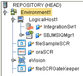
Set the environment variables (as shown in the figure below).
-
Create a deployment profile in the SCR project.
-
Create a deployment profile in the TesterGatekeeper project.
-
Deploy both the SCR and TesterGatekeeper deployment profiles.
Preparing an SCR flow
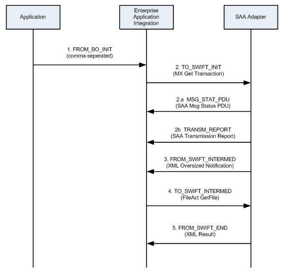
The SCR Workflow follows the tasks, procedural steps, required input and output information, for each step in the business process. The SCR workflow is used to view, manage, and enforce the consistent handling of work. The following figure is an example of a design of an SCR flow.
Designing an SCR flow
-
Start the Enterprise Designer.
-
Open the imported SCR project.
-
Choose both a short name and a long name for the flow (example: t2 :: Target2).
-
Choose a string name for each event / message / direction (as shown in the SCR flow example above: TO_SWIFT_INIT).
-
Add the flow name as a new choice in the viewer by navigating to the Viewer on the SCR page, then to the 1TrxList, and then to the pgTrxList.
-
On the Properties tab, select SelDomain.
-
Right-click the highlighted area on the design canvas, and select Edit Options. The Edit Options window opens.
-
Add new flow elements to the properties of the control SelDomain. This project already ahs defualted values entered (t2 :: Target2).
-
Linking the Domain Name and Direction to a Color
You can link the name of a Domain to specific pointer directions and colors within the monitoring application.
-
Link the domain name and the direction to a color by opening the SCR.properties file located in c:\SampleSCR\properties.
-
A list of available directions and colors are listed in the SCR properties file. Possible Colored Directions (CD) for message lists include:
-
DEFAULT
-
LGREY, RGREY
-
LBLUE, RBLUE
-
LGREEN, RGREEN
-
LORANGE, RORANGE
-
LRED, RRED
-
-
Link the Domain to a specific pointer directin and color by using the following Syntax: CD_<Direction String> = <Colored Directions>.
Using the SCR for Monitoring Flows
Applications that send events to the SCR must do two things:
-
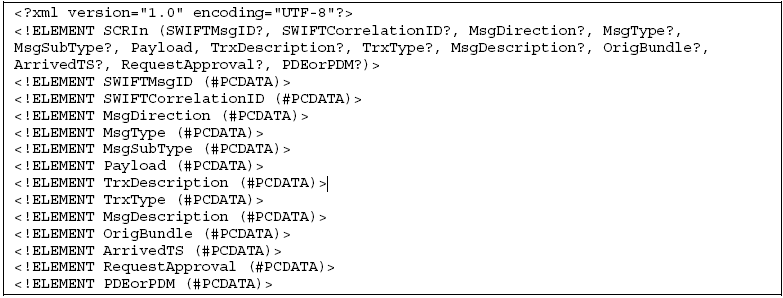
Create a message following the input format shown below. Do not use the field whose usage is indicated as “Gatekeeper only”.
-
Send the message to either:
-
A file in the c:\SampleSCR\In location, with a .txt extension and a name starting with Loader.
-
A JMS message to the JMS queue, qSCRInEnv, in SCR/Loader.
-
Using the Viewer for Monitoring Transactions
-
Use an Internet browser and navigate to the URL http://localhost:18001/scr. The Select Transaction window opens.
-
Use one of the following criteria for monitoring transactions:
-
Select the 10 most recently updated transactions from the drop-down list.
-
Use the domain selector to restrict the transaction list.
-
Search for a transaction with a specific ID.
-
Search for a transaction that contains a message with a specific ID.
-
-
Click the Search button.
Using the SCR as Gatekeeper
Applications sending events to the SCR as Gatekeeper must do two things:
-
Create a message following the input format (as shown in the previous section)
-
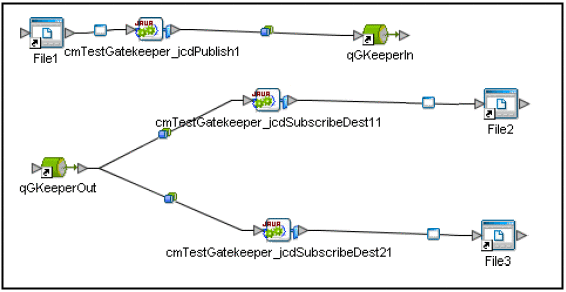
Send the message to the JMS queue “qGKeeperIn” in SCR/Gatekeeper. Make sure to add a JMS topic to the message. A code sample is shown below.
com.stc.connectors.jms.Message outMsg =
jmsPublish.createTextMessage();
outMsg.storeUserProperty( "SCRDestination", "DEST1" );
outMsg.setTextMessage( input.getText() );
jmsPublish.send( outMsg );
-
Subscribe to the JMS queue ”qGKeeperOut” in SCR/Gatekeeper.
-
Subscribe to the JMS topic that you used to publish the message.
Note –
A complete test setup is located in the project TesterGatekeeper.
Using the Viewer to Repair Messages
-
Use an Internet browser and navigate to the URL http://localhost:18001/scr. The Select Transaction window opens.
-
Select the 10 most recently updated transactions from the drop-down list. Messages that have been held for review and resubmittion (e.g. messages that are duplicates, incorrect, or awaiting approval) are displayed.
-
Select the message you wish to examine and click the Repair button. The Message Repair window opens, displaying detailed information regarding the message.
-
You can resolve the message in the following ways:
-
Correct the message error and click the Resubmit button.
-
Examine a message that requires approval and click the Approve button.
-
Delete the message by clicking the Delete button
-
SWIFT Sample eInsight™ Project
The SWIFT eInsight Sample Project (prjSwift_BP_Sample), an eInsight Project, uses an eInsight Business Process Service instead of the Java-based Collaborations used in the JCD sample. Before using this Project, you must first import it into eGate. See Importing a Sample Project for details on how to import a Project.
The SWIFT eInsight Sample project demonstrates the use of SWIFT OTDs in a Business Process, and provides an example of how to use the marshal() and unmarshal() operations included as part of every SWIFT OTD. This Project contains one Business Process.
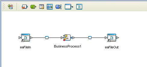
Figure 1 SWIFT eInsight Sample Project - Connectivity Map
Project Walkthrough
Figure 1 displays the Project’s Connectivity Map, which represents the flow of the Project as follows:
-
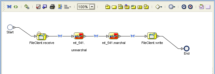
The Business Process (see Figure 2) begins with a File.read() operation. This operation subscribes to an external “input” directory and picks up a file that contains a valid SWIFT MT 541 message.
-
The File.read() operation publishes the message to the input of the mt_541.unmarshal() operation. This operation basically unmarshals the MT 541 message into a Java data structure that represents the message. This structure is the output of the mt_541.unmarshal() operation.
-
The Business Process continues by publishing this output to the input of the mt_541.marshal() operation. The mt_541.marshal() operation transforms the OTD data structure back into a String.
-
Finally, this String is published as input to the File.write() operation, which writes out the String to an external directory.
The Business Process itself is relatively simple, but it identifies how the operations of the SWIFT OTDs can be used in a Business Process.
Configuration of the Connectivity Map is simply the configuration of the Inbound and Outbound File eWay (see Figure 1). The configuration of the Inbound File eWay determines where the SWIFT MT 541 message is located. The configuration of the Outbound File eWay states where the output of the Business Process goes.
Note –
You must have the eInsight.sar file installed to use the features available with this Project. See the Sun Java Composite Application Platform Suite Installation Guide for complete installation procedures.
SWIFT eInsight Sample Project Data
A sample messages, as well as an example of a valid output message are located in the Swift_eInsight_Sample_Data folder (downloaded with the sample) as:
-
input_BP_Validmt541.txt.~in: sample valid message input file
-
Swift_Valid_BP_Output1.dat: example of sample valid message output
Using eGate With eInsight
You can set up and deploy eGate components using eInsight. Once you have associated the desired component (for example, a Service in this Project) with a Business Process, the eInsight engine can automatically invoke that component during run time, using a Business Process Execution Language (BPEL) interface.
The following eGate components are able to interface with eInsight:
-
Java Messaging Service (JMS)
-
Object Type Definitions (OTDs)
-
eWays
-
eGate Services
Using the eGate Enterprise Designer and its eInsight Editor, you can add an operation to a Business Process, then associate that process with an eGate component, for example, a Service. In the Enterprise Designer, associate the Business Process and the Service icons using drag-and-drop procedures.
See the eInsight Business Process Manager User’s Guide for details.
SWIFT OTD Library With eInsight
You can add SWIFT OTD Library objects to an eInsight Business Process during the system design phase. To create this association, select the desired operation, for example marshal or unmarshal, under the OTD in the Project Explorer, and drag it onto the eInsight Business Process Editor.
At run time, the eInsight Engine is able to invoke each of the steps in order of set up in the Business Process. Using the engine’s BPEL interface, eInsight in turn invokes the SWIFT OTD Library operations, as well as any eWays in the Business Process.
Table 12 shows the eInsight Business Process operations available to the SWIFT OTD Library, as well as a description of these operations.
Table 12 Available eInsight SWIFT OTD Business Process Operations|
eInsight Business Process Operation |
Description |
|---|---|
|
unmarshal |
Parses the SWIFT message/OTD for validation. |
|
marshal |
Readies the SWIFT message for writing, along with any errors. |
The Enterprise Designer’s Project Explorer should have the SWIFT OTD Library Business Process operations exposed under the OTD icon.
Using a Business Process
Once you have designed your Business Process for this sample, you can use the eInsight Business Process Designer and Editor to create it. Figure 2 displays the Business Process operations as created by the Business Process Editor.
Figure 2 Sample Project Business Process
Configuring the Modeling Elements
Business Rules are defined and configured between the Business Process Activities located on the modeling canvas. The sample Project contains the Business Rules that govern each of the Activities listed in a Business Process flow.
Each of the icons located on the links between Activities represent a Business Rule. The Business Rules found in the sample Project include:
Double-click one of the icons to open the Business Rule Designer pane.
Note –
A detailed description of the steps required to configure modeling elements is found in the Sun SeeBeyond eInsight Business Process Manager User’s Guide.
Copying the Output File
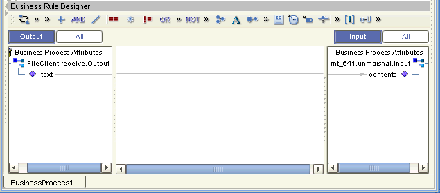
The FileClient.receive.Output container copies the output file containing the message to be used. The Business Process copies the message content to the input container, mt_541.unmarshal.Input, to be unmarshaled. See Figure 3.
Figure 3 Copying the Output File
Unmarshaling and Marshaling the Data
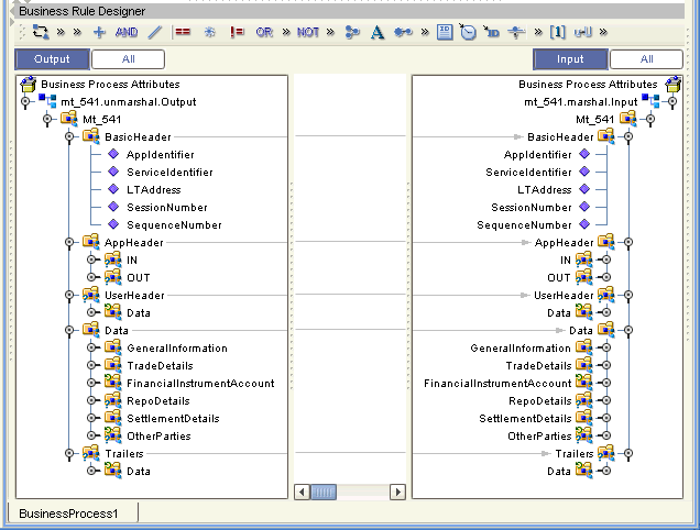
The Business Process unmarshals the data and marshals the data, using the mt_541.unmarshal and mt_541.marshal operations. The Business Process then writes the results to the FileClient.write.Output container. See Figure 4.
Figure 4 Unmarshaling and Marshaling the Data
Returning the Value
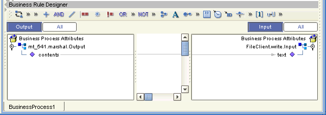
The OTD output container writes the resulting value to a text file using the FileClient.write.Input container. See Figure 5.
Figure 5 Returning the Requested Value
Creating a Connectivity Map
The Enterprise Designer’s Connectivity Map Editor provides a canvas for assembling and configuring a Project’s components. Connectivity Maps are used with both Java Collaboration (JCD) and eInsight (BP) Project implementations. The following sample demonstrates how the prjSwift_BP_Sample is created.
-
From the Enterprise Designer’s Project Explorer, right-click the prjSwift_BP_Sample Project and select New > Connectivity Map from the shortcut menu.
-
The New Connectivity Map appears and a node for the Connectivity Map is added under the Project on the Project Explorer tree labeled CMap1. Rename the Connectivity Map cmSwift_BP.
Selecting the External Applications
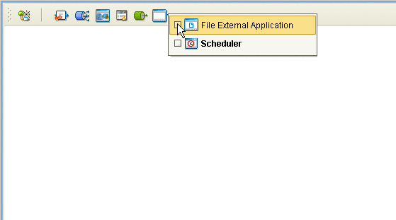
In the Connectivity Map, the eWays are associated with External Systems. For example, to establish a connection to an external file, you must first select File as an External System to use in your Connectivity Map (see Figure 6).
Figure 6 Connectivity Map - External Applications
-
Click the External Application icon on the Connectivity Map toolbar,
-
Select the external systems necessary to create your Project (for this sample, File. Icons representing the selected external systems are added to the Connectivity Map toolbar.
Populating the Connectivity Map
The icons in the toolbar represent the available components used to populate the Connectivity Map canvas. Add the Project components to the Connectivity Map by dragging the icons from the toolbar to the canvas.
-
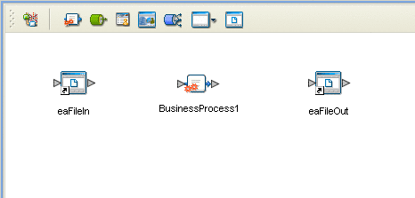
For this sample, drag the following components onto the Connectivity Map canvas as displayed in Populating the Connectivity Map:
-
File External System (2)
-
Service (A service is a container for Collaborations, Business Processes, eTL processes, and so forth)
-
Rename the File1 External Application to eaFileIn by right-clicking the object, selecting Rename from the shortcut menu, and typing in the new name. In the same way, rename the other Connectivity Map components as follows:
-
File2 to eaFileOut
-
cm_Swift_BP_Service1 to BusinessProcess1.
-
Save your current changes to the Repository.
Binding the eWay Components
Once the Connectivity Map has been populated, components are associated and bindings are created in the Connectivity Map.
-
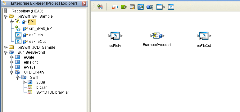
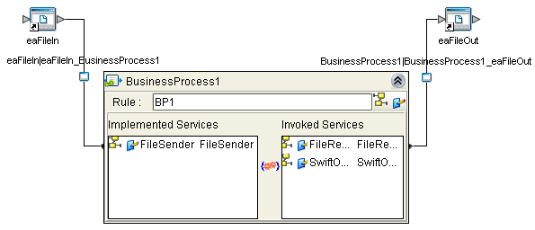
Drag and drop the BP1 Business Process, under prjSwift_BP_Sample, from the Project Explorer tree to the Service (BusinessProcess1). If the Business Process was successfully associated, the Service’s icon changes to a Business Process icon (see Binding the eWay Components).
-
Double-click the BusinessProcess1 Service. The BusinessProcess1 binding dialog box appears using the BP1 Rule.
-
From the BusinessProcess1 binding dialog box, map FileSender (under Implemented Services) to the eaFileIn (File) External Application. To do this, click on FileSender in the BusinessProcess1 binding dialog box, and drag the cursor to the output node of the eaFileIn External Application in the Connectivity Map. A link named eaFileIn|eaFileIn_BusinessProcess1 is now visible.
-
From the BusinessProcess1 binding dialog box, map FileReceiver (under Invoked Services) to the input node of the eaFileOut External Application (see Binding the eWay Components).
-
Minimize the BusinessProcess1 binding dialog box and save your current changes to the Repository.
Creating an Environment
Environments include the external systems, Logical Hosts, integration servers and message servers used by a Project and contain the configuration information for these components. Environments are created using the Enterprise Designer’s Environment Editor. The following example uses the prjSwift_BP_Sample Project.
-
From the Enterprise Designer’s Enterprise Explorer, click the Environment Explorer tab.
-
Right-click the Repository and select New Environment. A new Environment is added to the Environment Explorer tree.
-
Rename the new Environment to envSwift_BP_Sample.
-
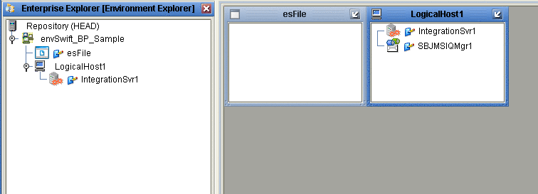
Right-click envSwift_BP_Sample and select New File External System. Name the External System esFile. Click OK. esFile is added to the Environment Editor.
-
Right-click envSwift_BP_Sample and select New Logical Host. The LogicalHost1 box is added to the Environment and LogicalHost1 is added to the Environment Editor tree.
-
Right-click LogicalHost1 and select New > Sun SeeBeyond Integration Server. A new Integration Server (IntegrationSvr1) is added to the Environment Explorer tree under LogicalHost1 (see Creating an Environment).
-
For the prjSwift_JCD_Sample only, the Environment must also include a JMS IQManager. To add an IQ Manager, right-click LogicalHost1 and select New > SeeBeyond JMS IQManager. A new JMS IQ Manager (SBJmsIQMgr1) is added to the Environment Explorer tree under LogicalHost1.
-
Save your current changes to the Repository.
Configuring the eWays
The sample Projects contains two component File eWays (inbound and outbound) represented in the Connectivity Map as a node between an File External Application and a Collaboration. The existing Connectivity Map property settings are sufficient for the sample, but the Environment property settings must be configured for your system as follows:
-
From the Environment Explorer tree, right-click the File External System (esFile in this sample), and select Properties. The Properties Editor opens to the File eWay Environment configuration.
-
From the Properties Editor, modify the Directory settings (Parameter Settings > Directory) for both the Inbound and Outbound File eWays, to correspond with inbound and outbound directories you created on your system. Click OK to accept the settings.
For more information on configuring the File eWay properties for your system, see the Sun SeeBeyond eWay™ File Adapter User’s Guide.
Configuring the Integration Server
You must set your Sun SeeBeyond Integration Server Password property before deploying your Project.
-
From the Environment Explorer, right-click IntegrationSvr1 under your Logical Host, and select Properties from the shortcut menu. The Integration Server Properties Editor appears.
-
Click the Password property field under Sun SeeBeyond Integration Server Configuration. An ellipsis appears in the property field.
-
Click the ellipsis. The Password Settings dialog box appears. Enter STC as the Specific Value and as the Confirm Password, and click OK.
-
Click OK to accept the new property and close the Properties Editor.
For more information on deploying a Project see the Sun SeeBeyond Java™ Composite Application Platform Suite Deployment Guide.
Creating the Deployment Profile
A Deployment Profile is used to assign Business Processes, Collaborations, and message destinations to the integration server and message server. Deployment Profiles are created using the Deployment Editor.
-
From the Project Explorer, right-click the Project (prjSwift_BP_Sample) and select New > Deployment Profile.
-
Enter a name for the Deployment Profile (for example, dpSwift_BP_Sample). Make sure that the selected Environment is envSwift_BP_Sample. Click OK.
-
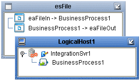
Click the Automap icon as displayed in Creating the Deployment Profile.

The Project’s components are automatically mapped to their system window as seen in Creating the Deployment Profile.
-
Save your changes to the Repository.
Creating and Starting the Domain
To deploy your Project, you must first create a domain. A domain is an instance of a Logical Host.
Create and Start the Domain
-
Navigate to your <JavaCAPS51>\logicalhost directory (where <JavaCAPS51> is the location of your Sun Java Composite Application Platform Suite installation.
-
Double-click the domainmgr.bat file. The Domain Manager appears.
-
If you have already created a domain, select your domain in the Domain Manager and click the Start an Existing Domain button. Once your domain is started, a green check mark indicates that the domain is running.
-
If there are no existing domains, a dialog box indicates that you can create a domain now. Click Yes. The Create Domain dialog box appears.
-
Make any necessary changes to the Create Domain dialog box and click Create. The new domain is added to the Domain Manager. Select the domain and click the Start an Existing Domain button. Once your domain is started, a green check mark indicates that the domain is running.
-
For more information about creating and managing domains see the Sun SeeBeyond eGate Integrator System Administration Guide.
Building and Deploying the Project
The Build process compiles and validates the Project’s Java files and creates the Project EAR file.
Build the Project
-
From the Deployment Editor toolbar, click the Build icon.
-
If there are any validation errors, a Validation Errors pane will appear at the bottom of the Deployment Editor and displays information regarding the errors. Make any necessary corrections and click Build again.
-
After the Build has succeeded you are ready to deploy your Project.
Deploy the Project
-
From the Deployment Editor toolbar, click the Deploy icon. Click Yes when the Deploy prompt appears.
-
A message appears when the project is successfully deployed.
Note –Projects can also be deployed from the Enterprise Manager. For more information about using the Enterprise Manager to deploy, monitor, and manage your projects, see the Sun SeeBeyond eGate™ Integrator System Administration Guide.
Running the Sample
To run your deployed sample Project do the following
-
From your configured input directory, paste (or rename) the sample input file to trigger the eWay.
-
From your output directory, verify the output data.
- © 2010, Oracle Corporation and/or its affiliates
