| Exit Print View | |
Sun Datacenter InfiniBand Switch 648 Topic Set |

|
Documentation, Support, and Training
Understanding the Installation
Fabric Card Handling Guidelines
Fabric Card and Line Card Fillers
Suggested Tools for Installation
Antistatic Precautions for Installation
Installing the InfiniBand Software Stack
Install the HPC Software Suite
Remove the Shipping Carton Contents
Unsecure the Chassis From the Pallet
Install the Rail Assemblies in the Rack
Inspecting the Midplane for Installation
Identify the Midplane Fabric Card Connectors
Inspect the Pins on the Rear Side of the Midplane
Identify the Midplane Line Card Connectors
Inspect the Pins on the Front Side of the Midplane
Inspecting the Fabric Cards for Installation
Identify the Fabric Cards for Installation
Inspect the Fabric Card Chassis for Installation
Inspect the Fabric Card Retainer Bolts for Installation
Inspect the Fans for Installation
Inspect the Fabric Card XBOW Connectors for Installation
Inspecting the Line Cards for Installation
Identify the Line Cards for Installation
Inspect the Line Card Chassis for Installation
Inspect the Line Card Retainer Bolts for Installation
Inspect the Line Card XBOW Connectors for Installation
Inspect the Line Card CXP Connectors for Installation
Inspecting the InfiniBand Cables for Installation
Identify the InfiniBand Cable for Installation
Inspect the InfiniBand Cable Hardware for Installation
Inspect the InfiniBand Cable Connectors for Installation
Install the Midplane Stiffener
Install the Fabric Cards or Fabric Card Fillers
Install the Line Cards or Line Card Fillers
Check the Power Supply Status LEDs
Access the CMC From the Serial Management Port
Set the Initial UBoot Parameters
Access the CMC From the Network Management Port
Display the CMC FRU ID Information
Verify the Power Supply Status
Identify the Power Supply Addresses
Display the Power Supply FRU ID Information
Enable the Fabric Cards for Installation
Create the guid.txt File for Installation
Power On the Fabric Cards for Installation
Check the Fabric Card Status LEDs
Identify the Fabric Card Addresses
Display the Fabric Card FRU ID Information
Enable the Line Cards for Installation
Power On the Line Cards for Installation
Check the Line Card Status LEDs
Identify the Line Card Addresses
Display the Line Card FRU ID Information
Attach Cables to the CXP Connectors
Check the CXP Connector Status LEDs
Identify the CXP Connector Addresses
Display the InfiniBand Cable FRU ID Information
Verifying the InfiniBand Fabric
Discover the InfiniBand Fabric Topology
Perform Diagnostics on the InfiniBand Fabric
Validate the InfiniBand Fabric and Report Errors
Understanding ILOM on the Switch
 | Caution - The switch with shipping cradle weighs approximately 286.0 lb (130.0 kg). To prevent personal injury, two people are needed to move the switch safely into the cabinet using a computer equipment lift. |
 | Caution - The shipping cradle must be attached when the switch is lifted. Failure to do so will result in major damage to the switch. |
 | Caution - Do not install any rail-mounted equipment in the Sun Datacenter InfiniBand Switch 648 rack. Oracle’s Sun Datacenter InfiniBand Switch 648 switches must be loaded into the rack from the bottom up. |
Identify the prerequisite and subsequent tasks you must perform in conjunction with this procedure, to install the switch.
See the table in ![]() Installation Sequence.
Installation Sequence.
Extend the rack stabilizer and lock it in position (as applicable).
Insert the forks of the lifting device fully through the shipping cradle opening.
Make the forks only as narrow as to permit clearance.
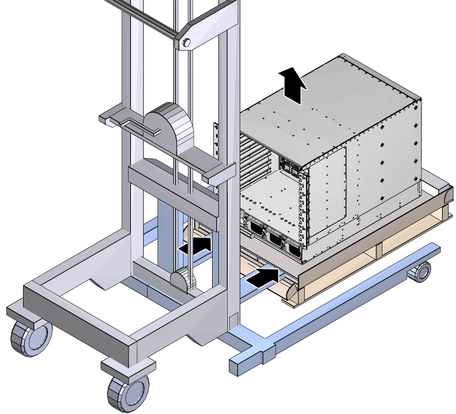
Lift the switch off the wooden shipping pallet and remove the pallet.
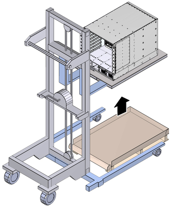
Note - Lift the switch only high enough to remove the pallet.
Slowly move the switch to the rack.
Set the lift height so that the chassis is equal with the rails on the rack.
Carefully move the lifting device forward as possible, until the switch chassis is able to slide safely on the rails.
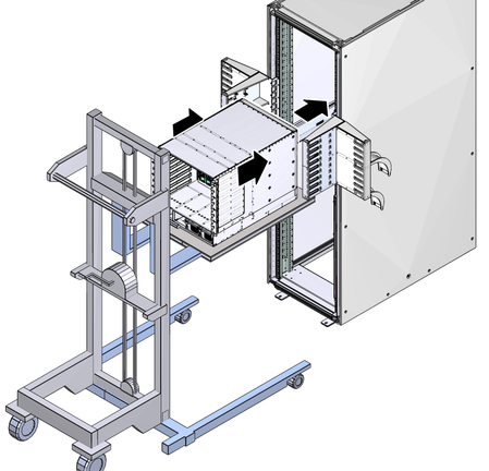
Slide the switch into the rack and against the cable trees.
Pull the lift back from the rack so that it clears the cable trees.
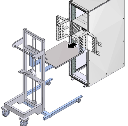
Lower the shipping cradle and move the lift out of the way.
Using a No. 2 Phillips screwdriver, install the 10 larger M6 screws on the front of the switch chassis to secure the switch to the rack posts.
Note - The screws enter recessed holes in the switch chassis flange for fastening.
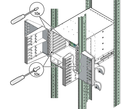
Install the 10 smaller M4 screws on the front of the switch chassis to secure the switch to the cable trees.
Note - The screws secure to the outer surface of the switch chassis flange.
Install the four M6 screws at the rear of the switch chassis to secure the switch to the rails.
Retract the cabinet stabilization mechanism (as required).
Inspect the switch components before installing them.