| Exit Print View | |
Sun Datacenter InfiniBand Switch 648 Topic Set |

|
Documentation, Support, and Training
Understanding the Installation
Fabric Card Handling Guidelines
Fabric Card and Line Card Fillers
Suggested Tools for Installation
Antistatic Precautions for Installation
Installing the InfiniBand Software Stack
Install the HPC Software Suite
Remove the Shipping Carton Contents
Unsecure the Chassis From the Pallet
Install the Rail Assemblies in the Rack
Install the Chassis in the Rack
Inspecting the Midplane for Installation
Identify the Midplane Fabric Card Connectors
Inspect the Pins on the Rear Side of the Midplane
Identify the Midplane Line Card Connectors
Inspect the Pins on the Front Side of the Midplane
Inspecting the Fabric Cards for Installation
Identify the Fabric Cards for Installation
Inspect the Fabric Card Chassis for Installation
Inspect the Fabric Card Retainer Bolts for Installation
Inspect the Fans for Installation
Inspect the Fabric Card XBOW Connectors for Installation
Inspecting the Line Cards for Installation
Identify the Line Cards for Installation
Inspect the Line Card Chassis for Installation
Inspect the Line Card Retainer Bolts for Installation
Inspect the Line Card XBOW Connectors for Installation
Inspect the Line Card CXP Connectors for Installation
Inspecting the InfiniBand Cables for Installation
Identify the InfiniBand Cable for Installation
Inspect the InfiniBand Cable Hardware for Installation
Inspect the InfiniBand Cable Connectors for Installation
Install the Midplane Stiffener
Install the Fabric Cards or Fabric Card Fillers
Install the Line Cards or Line Card Fillers
Check the Power Supply Status LEDs
Access the CMC From the Serial Management Port
Set the Initial UBoot Parameters
Access the CMC From the Network Management Port
Display the CMC FRU ID Information
Verify the Power Supply Status
Identify the Power Supply Addresses
Display the Power Supply FRU ID Information
Enable the Fabric Cards for Installation
Create the guid.txt File for Installation
Power On the Fabric Cards for Installation
Check the Fabric Card Status LEDs
Identify the Fabric Card Addresses
Display the Fabric Card FRU ID Information
Enable the Line Cards for Installation
Power On the Line Cards for Installation
Check the Line Card Status LEDs
Identify the Line Card Addresses
Display the Line Card FRU ID Information
Attach Cables to the CXP Connectors
Check the CXP Connector Status LEDs
Identify the CXP Connector Addresses
Display the InfiniBand Cable FRU ID Information
Verifying the InfiniBand Fabric
Discover the InfiniBand Fabric Topology
Perform Diagnostics on the InfiniBand Fabric
Validate the InfiniBand Fabric and Report Errors
Understanding ILOM on the Switch
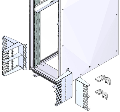
The cable trees have two parts, a main trunk and an outer branch. These pieces are left-right symmetrical and their orientation for installation can be determined as follows:
The main trunk installs at the front of the rack with the reinforcing ribs and cable shelf tabs toward the centerline of the rack. The square EMI screen mounting hole is at the bottom of the main trunk.
The outer branch installs onto the main trunk with the reinforcing ribs facing to the rear of the rack. The center reinforcing rib has 4 openings above and 5 openings below.
Note - For this procedure, the term cabinet holes refers to the holes in the posts of the cabinet. For the Sun Rack II cabinet, these holes are square. The holes are numbered from 1 starting at the very bottom. Hole 2, 3, 4, and so on, are the second, third, fourth, and so on, hole from the bottom. The numbering scheme printed on the posts is not used.
Note - This task requires two people.
Identify the prerequisite and subsequent tasks you must perform in conjunction with this procedure, to install the switch.
See the table in ![]() Installation Sequence.
Installation Sequence.
Bring the cable management hardware to the rack.
Identify the left main trunk and left outer branch.
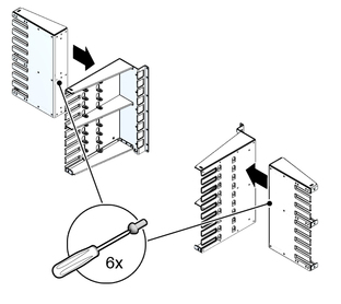
While holding the left main trunk and left outer branch together, have a helper install the three M4 mounting screws.
Install the first screw for the top hole on the main trunk.
Finger tighten the screw only.

Repeat ![]() Step a so that the middle and bottom screws are installed.
Step a so that the middle and bottom screws are installed.
Using a No. 2 Phillips screwdriver, securely tighten all three screws.
Set the assembled cable tree at the left front corner of the rack.

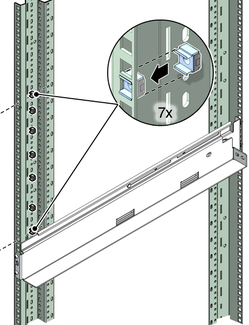
Insert the seven captive nuts for the left main trunk into cabinet holes a, b, c, d, e, f, and g.
where a, b, c, d, e, f, and g are the respective cabinet holes:
6, 8, 13, 19, 24, 30, and 33 for bottom mounting
40, 42, 47, 53, 58, 64, and 67 for middle mounting
74, 76, 81, 87, 92, 98, and 101 for top mounting

Lift the left cable tree into position.
Note - When in the correct position, the cable tree can rest upon the front flange of the slide rail.
Have a helper assist in aligning the cable tree mounting screw holes with the captive nuts in the rack.
While holding the cable tree in position, have a helper install the two M6 mounting screws.
Press the cable tree outward from the rack centerline and using a No. 2 Phillips screwdriver, firmly tighten the top and bottom screws.
Repeat ![]() Step 2 through
Step 2 through ![]() Step 9 for the right main trunk and right outer branch
at the front right corner of the chassis.
Step 9 for the right main trunk and right outer branch
at the front right corner of the chassis.
Consider your next steps: