| Exit Print View | |
Sun Netra CP3270 ATCA Blade Server User’s Guide |

|
Documentation, Support, and Training
Evaluating Product Compatibility
Preparing to Install the Blade Server
Installing Components and Blade Server
Installing Optional Components
Software and Firmware Upgrades
Software and Firmware Upgrades
Administering Parameters and Configurations
Advanced Rear Transition Module Connectors (Zone 3)
Administering User Accounts and Security
The front panel has the following connectors, as shown in the following figure:
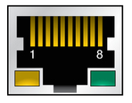
One 10/100/1000BASE-T Ethernet port (RJ-45), described in ![]() Ethernet Port
Ethernet Port
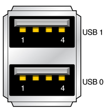
Two USB ports, described in ![]() USB Ports
USB Ports
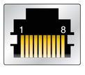
One serial port (RJ-45) described in ![]() Serial Port
Serial Port

Figure Legend
1 Ethernet port
2 Serial port
3 USB ports
4 AMC slot
The Ethernet connector is an RJ-45 connector. The controller autonegotiates to either 10 BASE-T, 100 BASE-T, or 1000 BASE-T.

See the following table for the Ethernet port pin assignments.
|
The following figure shows the connectors for the front panel USB ports.

The following table lists the pin assignments.
|
The following figure shows the connectors for the front panel serial port.

The following table lists the pin assignments.
|