JavaScript is required to for searching.
Skip Navigation Links
Exit Print View
StorageTek Dual 8 Gb FC Dual GbE ExpressModule HBA From QLogic Installation Guide

For HBA Models SG-PCIEFCGBE-Q8-Z, SG-XPCIEFCGBE-Q8-Z, SG-PCIEFCGBE-Q8-N, and SG-XPCIEFCGBE-Q8-N

Oracle Technology Network
Library
PDF
Print View
Feedback
search filter icon
search icon

Document Information

Using This Documentation

Chapter 1 HBA Overview

Chapter 2 Hardware Installation and Removal

Observing ESD and Handling Precautions

Installing the Hardware

To Install the HBA

Connecting the Cables to the HBA

To Connect the Cables to the HBA

To Power On the HBA

LED Descriptions and Status

LED and Switch Locations

Fibre Channel LED Indicator Status

Ethernet LED Indicator Status

Power and Attention Switch LED Scheme

Configuring the HBA for Hot-Plug Operation

To Configure the HBA for Hot-Plug Operation

Testing the Installation

To Test the Installation for the Oracle Solaris OS

Testing the Installation for the Windows OS

Testing the Installation for the VMware Technology

Removing the Hardware

To Prepare the HBA for Removal Using the HBA Attention Button

To Prepare the HBA for Hot-Plug Removal Using the Oracle Solaris OS

To Remove the HBA

Chapter 3 Software Installation

Chapter 4 Known Issues

Connecting the Cables to the HBA


Note - The HBA does not allow normal data transmission on an optical link unless it is connected to another similar or compatible Fibre Channel (FC) product (that is, multimode to multimode).

Use multimode fiber-optic cable, intended for short-wave lasers, that adheres to the specifications in the following table.

Fiber-Optic Cable
Maximum Length
Minimum Length
Connector
62.5/125 mm (multimode)
150 meters at 2.125 Gbit/second
70 meters at 4.25 Gbit/second
21 meters at 8.5 Gbit/second
2 meters
LC
50/125 mm (multimode)
300 meters at 2.125 Gbit/second
150 meters at 4.25 Gbit/second
50 meters at 8.5 Gbit/second
2 meters
LC

To Connect the Cables to the HBA

  1. Connect the fiber-optic cable(s) to LC connector(s) on the HBA.
  2. Connect the other end of the fiber-optic cable(s) to Fibre Channel device(s).
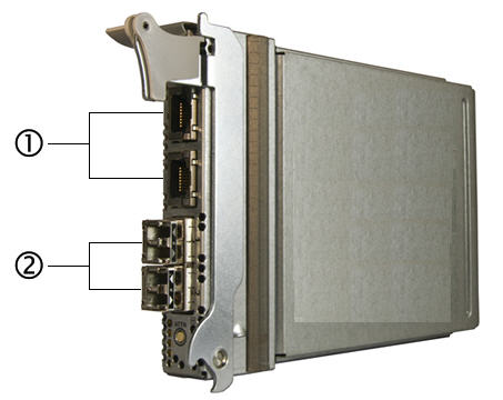
  3. Connect the Ethernet cable(s) to the Ethernet connector(s) on the HBA.
  4. Connect the other end of the Ethernet cable(s) to the Ethernet device(s).

    Figure 2-2  Attaching the Cables

    image:The figure shows where the Fibre Channel optical cables (bottom) and Ethernet cables (top) connect to the HBA.

    Figure Legend

    1 Connect Ethernet cable(s) to the Ethernet connector(s)

    2Connect fiber-optic cable(s) to the LC connector(s)

To Power On the HBA

After installing the hardware and connecting the cables, you can power on the HBA by pressing the Attention button.

  1. Verify that the HBA is securely installed in the system.
  2. Verify that the correct optical and Ethernet cables are attached.
  3. Refer to your system installation or service manual to determine how to power up the system blade.
  4. Watch the Light-Emitting Diodes (LEDs) status for the power-on self test (POST) results as shown in Fibre Channel LED Indicator Status Definitions, Ethernet LED Indicator Status Definitions, and Power and Attention LED Scheme.